EP0992591B1 - Grain-oriented electrical steel sheet and production method thereof - Google Patents
Grain-oriented electrical steel sheet and production method thereof Download PDFInfo
- Publication number
- EP0992591B1 EP0992591B1 EP99119133A EP99119133A EP0992591B1 EP 0992591 B1 EP0992591 B1 EP 0992591B1 EP 99119133 A EP99119133 A EP 99119133A EP 99119133 A EP99119133 A EP 99119133A EP 0992591 B1 EP0992591 B1 EP 0992591B1
- Authority
- EP
- European Patent Office
- Prior art keywords
- steel sheet
- grooves
- grain
- melted
- oriented electrical
- Prior art date
- Legal status (The legal status is an assumption and is not a legal conclusion. Google has not performed a legal analysis and makes no representation as to the accuracy of the status listed.)
- Expired - Lifetime
Links
Images

Classifications
-
- C—CHEMISTRY; METALLURGY
- C21—METALLURGY OF IRON
- C21D—MODIFYING THE PHYSICAL STRUCTURE OF FERROUS METALS; GENERAL DEVICES FOR HEAT TREATMENT OF FERROUS OR NON-FERROUS METALS OR ALLOYS; MAKING METAL MALLEABLE, e.g. BY DECARBURISATION OR TEMPERING
- C21D8/00—Modifying the physical properties by deformation combined with, or followed by, heat treatment
- C21D8/12—Modifying the physical properties by deformation combined with, or followed by, heat treatment during manufacturing of articles with special electromagnetic properties
- C21D8/1294—Modifying the physical properties by deformation combined with, or followed by, heat treatment during manufacturing of articles with special electromagnetic properties involving a localized treatment
-
- C—CHEMISTRY; METALLURGY
- C21—METALLURGY OF IRON
- C21D—MODIFYING THE PHYSICAL STRUCTURE OF FERROUS METALS; GENERAL DEVICES FOR HEAT TREATMENT OF FERROUS OR NON-FERROUS METALS OR ALLOYS; MAKING METAL MALLEABLE, e.g. BY DECARBURISATION OR TEMPERING
- C21D8/00—Modifying the physical properties by deformation combined with, or followed by, heat treatment
- C21D8/12—Modifying the physical properties by deformation combined with, or followed by, heat treatment during manufacturing of articles with special electromagnetic properties
-
- B—PERFORMING OPERATIONS; TRANSPORTING
- B23—MACHINE TOOLS; METAL-WORKING NOT OTHERWISE PROVIDED FOR
- B23K—SOLDERING OR UNSOLDERING; WELDING; CLADDING OR PLATING BY SOLDERING OR WELDING; CUTTING BY APPLYING HEAT LOCALLY, e.g. FLAME CUTTING; WORKING BY LASER BEAM
- B23K26/00—Working by laser beam, e.g. welding, cutting or boring
- B23K26/02—Positioning or observing the workpiece, e.g. with respect to the point of impact; Aligning, aiming or focusing the laser beam
- B23K26/06—Shaping the laser beam, e.g. by masks or multi-focusing
- B23K26/0604—Shaping the laser beam, e.g. by masks or multi-focusing by a combination of beams
- B23K26/0619—Shaping the laser beam, e.g. by masks or multi-focusing by a combination of beams with spots located on opposed surfaces of the workpiece
-
- B—PERFORMING OPERATIONS; TRANSPORTING
- B23—MACHINE TOOLS; METAL-WORKING NOT OTHERWISE PROVIDED FOR
- B23K—SOLDERING OR UNSOLDERING; WELDING; CLADDING OR PLATING BY SOLDERING OR WELDING; CUTTING BY APPLYING HEAT LOCALLY, e.g. FLAME CUTTING; WORKING BY LASER BEAM
- B23K26/00—Working by laser beam, e.g. welding, cutting or boring
- B23K26/36—Removing material
- B23K26/362—Laser etching
- B23K26/364—Laser etching for making a groove or trench, e.g. for scribing a break initiation groove
-
- C—CHEMISTRY; METALLURGY
- C22—METALLURGY; FERROUS OR NON-FERROUS ALLOYS; TREATMENT OF ALLOYS OR NON-FERROUS METALS
- C22B—PRODUCTION AND REFINING OF METALS; PRETREATMENT OF RAW MATERIALS
- C22B3/00—Extraction of metal compounds from ores or concentrates by wet processes
- C22B3/20—Treatment or purification of solutions, e.g. obtained by leaching
- C22B3/26—Treatment or purification of solutions, e.g. obtained by leaching by liquid-liquid extraction using organic compounds
- C22B3/38—Treatment or purification of solutions, e.g. obtained by leaching by liquid-liquid extraction using organic compounds containing phosphorus
- C22B3/385—Thiophosphoric acids, or esters thereof
-
- B—PERFORMING OPERATIONS; TRANSPORTING
- B23—MACHINE TOOLS; METAL-WORKING NOT OTHERWISE PROVIDED FOR
- B23K—SOLDERING OR UNSOLDERING; WELDING; CLADDING OR PLATING BY SOLDERING OR WELDING; CUTTING BY APPLYING HEAT LOCALLY, e.g. FLAME CUTTING; WORKING BY LASER BEAM
- B23K2103/00—Materials to be soldered, welded or cut
- B23K2103/02—Iron or ferrous alloys
- B23K2103/04—Steel or steel alloys
-
- Y—GENERAL TAGGING OF NEW TECHNOLOGICAL DEVELOPMENTS; GENERAL TAGGING OF CROSS-SECTIONAL TECHNOLOGIES SPANNING OVER SEVERAL SECTIONS OF THE IPC; TECHNICAL SUBJECTS COVERED BY FORMER USPC CROSS-REFERENCE ART COLLECTIONS [XRACs] AND DIGESTS
- Y02—TECHNOLOGIES OR APPLICATIONS FOR MITIGATION OR ADAPTATION AGAINST CLIMATE CHANGE
- Y02P—CLIMATE CHANGE MITIGATION TECHNOLOGIES IN THE PRODUCTION OR PROCESSING OF GOODS
- Y02P10/00—Technologies related to metal processing
- Y02P10/20—Recycling
Definitions
- This invention relates to a grain-oriented electrical steel sheet that retains a low iron loss and a high magnetic flux density even after stress-relief annealing and can be applied to both of a stacked core and a wound core, and a method of producing the same.
- the newly generated closure magnetic domain in this way increases the static magnetic energy but the magnetic domain is finely divided in such a manner as to minimize this increased static magnetic energy with the result that the iron loss can be improved. Due to the improvement of the iron loss by this domain fine dividing effect, the iron loss value can be lowered to a minimum value that is determined by the degree of crystal orientation of the material. Since this prior art method does not involve any physical deformation that would otherwise greatly impede the magnetic flux density, the method is almost free from a drop in the magnetic flux density after the laser irradiation.
- the grain-oriented electrical steel sheet produced by this method exhibits ideal magnetic properties.
- the iron loss lowering effect in the grain-oriented electrical steel sheet produced by the prior art method cannot withstand stress-relief annealing, that is conducted at about 800°C in a production process for a wound iron core, and disappears.
- the grain-oriented electrical steel sheet produced by this method cannot be used for wound cores, but is used exclusively for stacked cores.
- the grooves are formed on only one of the surfaces of the steel sheets.
- the depth of the grooves must be from about 15 to 30 ⁇ m when the steel sheet thickness is 0.23 mm, in order to obtain a practically sufficient iron loss lowering effect, though the groove depth varies depending on the means employed for forming the grooves. In other words, a deep groove exceeding 5% of the sheet thickness must be formed. Because the iron loss lowering effect considerably changes with the change of the groove depth, the groove depth must be controlled carefully. Therefore, the conventional products are not yet free from the following problems in the product properties and in the production method.
- the problems in the product properties will be explained. Because the deep groove that exceeds 15 ⁇ m, or 5% of the sheet thickness, is formed physically in the surface layer of the steel sheet, there exists a great hindrance to the magnetic flux density. In other words, the problem remains in that the magnetic flux density occurring in an arbitrary external magnetic flux drops greatly after the formation of the groove when compared with the magnetic flux density before the formation of the groove. Furthermore, because the iron loss lowering effect considerably changes with the change of the groove depth, variance in the iron loss characteristics of the products becomes great unless the groove depth is sufficiently controlled.
- the chemical etching method requires a long etching time, and the processing speed is limited. To improve the etching rate, a longer etching tank becomes necessary. In the case of the laser method, too, the laser power must be increased for deep groove processing. In consequence, the setup becomes greater in size, and a plurality of large laser generators are necessary.
- the irradiation laser power is increased in the case of the laser method, the influence of heat is excessively applied to the peripheral portions of the irradiated portion, so that swell deformation occurs throughout the steel sheet. If such steel sheets are stacked to produce the stacked core, the iron loss increases or a space factor is deteriorated. Therefore, the steel sheet in which deep grooves are formed by the laser method involves still another problem in that the steel sheet cannot be used for the stacked core.
- the laser method is an excellent technology because it can execute non-contact high speed processing, has simple process and is excellent in controllability of the groove depth and positional accuracy of the groove formation positions.
- it involves the problem that when a deep groove is to be formed, it imparts an excessive heat influence onto the peripheral portions of the irradiated portion and invites the deformation of the steel sheet that would deteriorate the magnetic properties.
- the inventors have formed various grooves and/or heat-affected layers on a grain-oriented electrical steel sheet by the laser method, and have examined in detail the magnetic properties after the steel sheet is subjected to stress-relief annealing. As a result, the inventors have found that extremely excellent magnetic properties can be obtained in comparison with those of the conventional grain-oriented electrical steel sheet, by forming either heat-affected layers or grooves and heat-affected layers on both surfaces of the steel sheet.
- the present invention has been achieved on the basis of the finding described above, and the gist of the present invention resides in the following points.
- the groove depth on both surfaces of the steel sheet is preferably limited to 5% or less of the steel sheet. Therefore, the grain-oriented electrical steel sheet of the present invention is almost free from the drop of the magnetic flux density.
- the formation positions of the heat-affected layers or of the grooves and the heat-affected layers on both surfaces of the steel sheet form pairs, and their positional deviation is not greater than the width of the heat-affected layers or of the grooves and the heat-affected layers in the rolling direction. Therefore, the steel sheet can provide a large lowering effect of the iron loss and at the same time, is free from the swell deformation that is the problem in the steel sheet for the stacked core. In consequence, the steel sheet can be applied to both the stacked core and the wound core.
- the present invention uses beams having high energy, particularly a continuous wave or a pulse laser, the present invention provides a production method for a grain-oriented electrical steel sheet capable of forming either the heat-affected layers or the grooves and the heat-affected layers on both surfaces of the steel sheet with high positional accuracy.
- the heat-affected layer is defined in the present invention as melted and resolidified layers that are formed by the irradiation of the high energy beams such as laser, electron beams, and so forth.
- a layer has a permeability different from that of the steel sheet base metal and has a layer volume to such an extent as to be capable of providing a magnetic domain refinement effect to the steel sheet.
- This heat-affected layer can be easily confirmed by observing a section of the steel sheet through a microscope.
- the production method of the grain-oriented electrical steel sheet according to the present invention forms grooves and heat-affected layers, or only the heat-affected layers, on both surfaces of the grain-oriented electrical steel sheet.
- These heat-affected layers or grooves and heat-affected layers are formed by high energy processing technologies using laser energy, electron beams, ion beams, plasma, and so forth.
- the technology that uses a laser is most preferred as the production method of the grain-oriented electrical steel sheet according to the present invention from the aspects of beam irradiation positional accuracy, controllability of the formation of heat-affected layers or of the grooves and heat-affected layers and usability in atmospheric air, in comparison with methods using other energy beams.
- the object of the invention can be provided if only heat-affected layers or grooves and heat-affected layers for a resistance to heat applied by annealing are formed on the surface layers of the final product. Therefore, the heat-affected layers or grooves and heat-affected layers may be formed at any process steps of an ordinary production process of the grain-oriented electrical steel sheets.
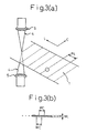
- the grain-oriented electrical steel sheet according to the present invention will be explained where a laser is used as the energy beam source, by way of example.
- a laser is used as the energy beam source, by way of example.
- the steel sheet base metal at its irradiated portion is melted instantaneously, and almost all the irradiated portion evaporates, thereby forming a groove.
- heat-affected layers are slightly formed on the side surface and the bottom of the groove so formed.
- the heat-affected layer does not exhibit by itself the magnetic domain refinement effect, though its permeability is different from that of the base metal. Therefore, this heat-affected layer is not included in the heat-affected layer that is defined in the present invention.
- the groove formed thereby is essentially the same as the groove that is formed without applying heat at all such as by a etching process.
- the metal of the irradiated portion is not evaporated.
- the amount of the components that are re-solidified from the melt state increases, the groove is formed and, at the same time, a heat-affected layer that has a thickness substantially equal to the groove depth and comprises a melted and re-solidified layer is formed. Since the permeability of this heat-affected layer is different from the permeability of the base metal, it changes the magnetic field in the same way as the groove. In other words, this heat-affected layer has the domain refinement effect. Therefore, this heat-affected layer is included in the heat-affected layers defined in the present invention.
- the metal of the irradiated portion does not reach the melting point, and melted and resolidified layers devoid of a groove formation are formed. Even in such a case, the laser irradiated portion has a certain repeated heating-cooling cycle, and its permeability is therefore different from that of the base metal. As a result, this layer exhibits the domain refinement effect. For this reason, this layer is included in the heat-affected layers defined in the present invention.
- the present invention can provide a grain-oriented electrical steel sheet that has both a high magnetic flux density and a low iron loss, has extremely stable properties and can be applied to both of the stacked core and the wound core.
- the depth of the groove to be formed is small, and the groove depth need not be strictly controlled. Therefore, the load on production setups can be mitigated.
- the high energy beam, particularly the laser beam is used for the production method of the present invention, the optimum heat-affected layers or grooves and heat-affected layers can be formed easily and with high accuracy.
- Fig. 3(a) is an explanatory view useful for explaining the grain-oriented electrical steel sheet and the production method thereof according to the present invention.
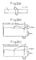
- Fig. 1(a) shows various sectional shapes of the grain-oriented electrical steel sheets having such grooves and/or heat-affected layers formed in this way, and Fig. 1(b) shows in enlargement the grooves 2 and the heat-affected layers 3 formed in this way.
- the diameter of the focused laser beam was 0.1 mm in the L direction and 0.3 mm in the C direction.
- the dotted line-like gap PC in the C direction was 0.30 mm.
- the depth of the groove is defined by the maximum value d of the dep t h as shown in Fig 1(b). Deviation of the groove formation positions on both surfaces is defined by a value g shown in Fig. 2(a).
- Table 1 shows the evaluation result of the magnetic properties of each steel sheet.
- the iron loss value was an iron loss value W17/50 at 50 Hz and the maximum magnetic flux density 1.7T, and the magnetic flux density was a value B8 at a magnetizing force 0.8 A/m.
- the steel sheet was a 0.23 mm-thick grain-oriented electrical steel sheet having an insulating film on the surface thereof.
- the magnetic properties of the steel sheet the iron loss of which was reduced by laser strain, and which was for exclusive use for a stacked core are also shown in the table.
- the laser irradiation condition, and the conditions for the grooves, the heat-affected layers, etc, of each steel sheet are listed below. Incidentally, the existence of the grooves and the heat-affected layer was confirmed by inspecting the section of the steel sheet through a microscope.
- Grooves having a depth of 30 ⁇ m were formed on both surfaces of the steel sheet by Q switch pulse CO 2 laser.
- the peak power density of the Q switch pulse CO 2 laser was about 10 to about 30 MW/mm 2 , and the pulse time total width was 20 ⁇ s.
- the laser irradiated portion was evaporated almost fully by the high peak pulse processing.
- the heat-affected layer defined by the present invention did not exist at the irradiated portion, and only the grooves existed.
- the deviation g of the groove formation positions on both surfaces of the steel sheet was about 1.5 mm, and was greater than the width WL of the grooves in the L direction.
- Grooves having a depth of 30 ⁇ m were formed on both surfaces of the steel sheet by Q switch pulse CO 2 laser.
- the peak power density of the Q switch pulse CO 2 laser was about 10 to about 30 MW/mm 2 , and the pulse time total width was 20 ⁇ s.
- the laser irradiated portion was evaporated almost fully.
- the heat-affected layer defined by the present invention did not exist at the irradiated portion, and only the grooves existed.
- the deviation g of the groove formation positions on both surfaces of the steel sheet was about 0.1 mm, and was smaller than the width WL of the grooves in the L direction.
- Grooves having a depth of 10 ⁇ m were formed on both surfaces of the steel sheet by pulse modulated CO 2 laser.
- the peak power density of the pulse laser was 0.4 to 0.8 MW/mm 2 , and the pulse time total width was 20 ⁇ s. Because of the decrease of the pulse peak power, the grooves and the heat-affected layers that are defined by the present invention existed in mixture at the irradiated portion.
- the deviation g of the groove formation positions on both surfaces of the steel sheet was 0.1 mm, and was smaller than the width WL of the grooves in the L direction.
- Grooves having a depth of 5 ⁇ m were formed on both surfaces of the steel sheet by Q switch pulse CO 2 laser.
- the peak power density of the Q switch pulse CO 2 laser was about 10 to about 30 MW/mm 2 , and the pulse time total width was 12 ⁇ s. Because of high peak pulse processing, the laser irradiated portion was evaporated almost fully.
- the heat-affected layer defined by the present invention did not exist at the irradiated portion, and only the grooves existed.
- the deviation g of the groove formation positions on both surfaces of the steel sheet was about 0.1 mm, and was smaller than the width WL of the grooves in the L direction.
- Grooves having a depth of 5 ⁇ m were formed on both surfaces of the steel sheet by pulse modulated CO 2 laser.
- the peak power density of the pulse laser was 0.4 to 0.8 MW/mm 2 and the pulse time total width was 12 ⁇ s. Because of the decrease of the pulse peak power, the grooves and the heat-affected layer that are defined by the present invention existed in mixture at the irradiated portion.
- the deviation g of the groove formation positions on both surfaces of the steel sheet was 0.1 mm, and was smaller than the width WL of the grooves in the L direction.
- the peak power density of the pulse laser was 0.2 MW/mm 2
- the pulse time total width was 7 ⁇ s. Because of the further decrease of the pulse peak power, only the heat-affected layers defined by the present invention existed on the surface.
- the deviation g of the formation positions of the heat-affected layers on both surfaces of the steel sheet was 0.1 mm, and was smaller than the width WL of the heat-affected layers in the L direction.
- the steel sheet G was a conventional steel sheet, in which grooves having a depth of 30 ⁇ m were formed on only one of the surfaces of the steel sheet by Q switch pulse CO 2 laser.
- the peak power density of the Q switch pulse CO 2 laser was about 10 to about 30 MW/mm 2 , and the pulse time total width was 20 ⁇ s.
- the laser irradiated portion was evaporated almost fully due to the high peak pulse processing.
- the heat-affected layers that were defined by the present invention did not exist at the irradiated portion, and only the grooves existed.
- the result of the comparison of the magnetic properties of the steel sheets A to G revealed that the grain-oriented electrical steel sheets according to the present invention having either the heat-affected layers or the grooves and the heat-affected layers on both surfaces of the steel sheet exhibited a drop of the iron loss which was equal to, or greater than, that of the conventional grain-oriented electrical steel sheet having similar grooves on only one of the surfaces thereof.
- the grain-oriented electrical steel sheets according to the present invention could provide an iron loss reducing effect, that was equivalent to, or higher than, the effect of the prior art, by the grooves shallower than the grooves of the steel sheet of the prior art having the grooves on only one of the surfaces thereof. It was found that in an extreme case, the formation of the grooves were almost unnecessary.
- the grain-oriented electrical steel sheet having either the heat-affected layers or the grooves and the heat-affected layers on both surfaces thereof according to the present invention was not a mere modification of the conventional grain-oriented electrical steel sheet having the grooves formed on one of the surfaces thereof so as to improve the iron loss, or the conventional grain-oriented electrical steel sheet not having the resistance to disappear by annealing, though the strain was imparted by the laser to the surfaces so as to reduce the iron loss.
- the iron loss of the steel sheet H (prior art product), which was lowered by imparting the strain by the reaction of evaporation of the film due to the laser irradiation, was reduced to a value approximate to the limit that was determined by the degree of crystal orientation.
- the grain-oriented electrical steel sheet having either the heat-affected layers or the grooves and the heat-affected layers on both surfaces thereof could provide an iron loss value equivalent to that of the former.
- the change quantities of the magnetic flux density B8 were compared, it was found that in the steel sheets C and E, in which the grooves having a depth of not greater than 10 ⁇ m corresponding to 5% or less of the sheet thickness, were formed in accordance with the present invention, the B8 change quantity was not greater than 30 Gauss and the magnetic flux density B8 hardly changed. This was because the grooves that impeded the magnetic flux density were extremely shallow.
- the iron loss value could be stably lowered by the present invention irrespective of the depth of the grooves formed in the surface layer of the steel sheet.
- grain-oriented electrical steel sheets almost devoid of the drop of the magnetic flux density could be obtained by forming the grooves to a depth of not greater than 5%.
- Fig. 2(a) is an explanatory view of the deviation g of the formation positions of the grooves formed on both surfaces of the steel sheet by the laser process and the width WL of these grooves in the rolling direction.
- Figs. 2(b) and 2(c) show the measurement result of the surface coarseness of the steel sheets after stress-relief annealing, that is, the swell deformation quantity h.
- Symbol X in these drawings represents the groove positions.
- the deformation on the surface is corrected by the groove formation on both surfaces of the steel sheet. Therefore, there is the possibility that a local strain is imparted into the steel sheet. It is believed that this local stress-strain also exhibits the domain refinement effect.
Landscapes
- Engineering & Computer Science (AREA)
- Physics & Mathematics (AREA)
- Chemical & Material Sciences (AREA)
- Optics & Photonics (AREA)
- Mechanical Engineering (AREA)
- Materials Engineering (AREA)
- Organic Chemistry (AREA)
- Manufacturing & Machinery (AREA)
- Metallurgy (AREA)
- Electromagnetism (AREA)
- Crystallography & Structural Chemistry (AREA)
- Thermal Sciences (AREA)
- Plasma & Fusion (AREA)
- Life Sciences & Earth Sciences (AREA)
- Environmental & Geological Engineering (AREA)
- General Life Sciences & Earth Sciences (AREA)
- Geochemistry & Mineralogy (AREA)
- Geology (AREA)
- Manufacturing Of Steel Electrode Plates (AREA)
- Soft Magnetic Materials (AREA)
- Laser Beam Processing (AREA)
Applications Claiming Priority (2)
| Application Number | Priority Date | Filing Date | Title |
|---|---|---|---|
| JP28403498A JP4319715B2 (ja) | 1998-10-06 | 1998-10-06 | 磁気特性の優れた一方向性電磁鋼板とその製造方法 |
| JP28403498 | 1998-10-06 |
Publications (3)
| Publication Number | Publication Date |
|---|---|
| EP0992591A2 EP0992591A2 (en) | 2000-04-12 |
| EP0992591A3 EP0992591A3 (en) | 2001-02-07 |
| EP0992591B1 true EP0992591B1 (en) | 2005-01-12 |
Family
ID=17673453
Family Applications (1)
| Application Number | Title | Priority Date | Filing Date |
|---|---|---|---|
| EP99119133A Expired - Lifetime EP0992591B1 (en) | 1998-10-06 | 1999-10-05 | Grain-oriented electrical steel sheet and production method thereof |
Country Status (6)
| Country | Link |
|---|---|
| EP (1) | EP0992591B1 (enExample) |
| JP (1) | JP4319715B2 (enExample) |
| KR (1) | KR100372058B1 (enExample) |
| CN (1) | CN1090242C (enExample) |
| CA (1) | CA2284466C (enExample) |
| DE (1) | DE69923134T2 (enExample) |
Cited By (2)
| Publication number | Priority date | Publication date | Assignee | Title |
|---|---|---|---|---|
| RU2576282C2 (ru) * | 2011-12-28 | 2016-02-27 | ДжФЕ СТИЛ КОРПОРЕЙШН | Текстурированный лист электротехнической стали и способ его изготовления |
| US20210317545A1 (en) * | 2018-08-28 | 2021-10-14 | Posco | Grain-oriented electrical steel sheet and method for refining magnetic domain of same |
Families Citing this family (38)
| Publication number | Priority date | Publication date | Assignee | Title |
|---|---|---|---|---|
| DE60139222D1 (de) * | 2000-04-24 | 2009-08-27 | Nippon Steel Corp | Kornorientiertes Elektroblech mit ausgezeichneten magnetischen Eigenschaften |
| JP4091749B2 (ja) * | 2000-04-24 | 2008-05-28 | 新日本製鐵株式会社 | 磁気特性の優れた方向性電磁鋼板 |
| JP4398666B2 (ja) * | 2002-05-31 | 2010-01-13 | 新日本製鐵株式会社 | 磁気特性の優れた一方向性電磁鋼板およびその製造方法 |
| JP2006117964A (ja) * | 2004-10-19 | 2006-05-11 | Nippon Steel Corp | 磁気特性の優れた方向性電磁鋼板とその製造方法 |
| JP4705382B2 (ja) * | 2005-02-25 | 2011-06-22 | 新日本製鐵株式会社 | 一方向性電磁鋼板およびその製造方法 |
| JP4846429B2 (ja) * | 2005-05-09 | 2011-12-28 | 新日本製鐵株式会社 | 低鉄損方向性電磁鋼板およびその製造方法 |
| JP4775699B2 (ja) * | 2005-09-02 | 2011-09-21 | 日立金属株式会社 | レーザによる両面溝加工装置及び両面溝加工方法 |
| JP4772924B2 (ja) * | 2009-03-11 | 2011-09-14 | 新日本製鐵株式会社 | 方向性電磁鋼板及びその製造方法 |
| JP5740854B2 (ja) * | 2010-06-29 | 2015-07-01 | Jfeスチール株式会社 | 方向性電磁鋼板 |
| TWI417394B (zh) | 2010-09-09 | 2013-12-01 | Nippon Steel & Sumitomo Metal Corp | 方向性電磁鋼板及其製造方法 |
| CN102477484B (zh) * | 2010-11-26 | 2013-09-25 | 宝山钢铁股份有限公司 | 一种快速激光刻痕方法 |
| JPWO2012172624A1 (ja) * | 2011-06-13 | 2015-02-23 | 新日鐵住金株式会社 | 一方向性電磁鋼板の製造方法 |
| WO2012172624A1 (ja) * | 2011-06-13 | 2012-12-20 | 新日鐵住金株式会社 | 一方向性電磁鋼板の製造方法 |
| US10804015B2 (en) | 2011-12-29 | 2020-10-13 | Posco | Electrical steel sheet and method for manufacturing the same |
| WO2013161863A1 (ja) * | 2012-04-27 | 2013-10-31 | 新日鐵住金株式会社 | 方向性電磁鋼板及びその製造方法 |
| JP6003341B2 (ja) * | 2012-07-27 | 2016-10-05 | Jfeスチール株式会社 | 鋼板の加工状態評価方法および鋼板の加工状態評価装置 |
| KR101385742B1 (ko) * | 2012-11-12 | 2014-04-24 | 주식회사 포스코 | 방향성 전기강판의 자구 미세화 방법 |
| RU2604550C1 (ru) | 2012-11-26 | 2016-12-10 | Ниппон Стил Энд Сумитомо Метал Корпорейшн | Лист текстурованной электротехнической стали и способ изготовления листа текстурованной электротехнической стали |
| KR101538778B1 (ko) * | 2013-12-24 | 2015-07-22 | 주식회사 포스코 | 방향성 전기강판 및 그 제조방법 |
| JP2015140470A (ja) * | 2014-01-30 | 2015-08-03 | Jfeスチール株式会社 | 方向性電磁鋼板およびその製造方法 |
| KR102466500B1 (ko) * | 2015-12-22 | 2022-11-10 | 주식회사 포스코 | 방향성 전기강판 및 방향성 전기강판 적층체 |
| KR101751525B1 (ko) | 2015-12-24 | 2017-07-11 | 주식회사 포스코 | 방향성 전기강판 및 그의 제조 방법 |
| EP3399058A4 (en) * | 2015-12-30 | 2018-11-14 | Posco | Method for refining magnetic domain of grain-oriented electrical steel sheet, and device therefor |
| KR102148383B1 (ko) | 2016-01-22 | 2020-08-26 | 주식회사 포스코 | 방향성 전기강판의 자구미세화 방법과 그 장치 |
| KR101884429B1 (ko) | 2016-12-22 | 2018-08-01 | 주식회사 포스코 | 방향성 전기강판 및 그 자구미세화 방법 |
| US11254994B2 (en) | 2016-12-23 | 2022-02-22 | Posco | Method for refining magnetic domain of grain-oriented electrical steel plate and device therefor |
| CN107502723A (zh) * | 2017-09-15 | 2017-12-22 | 武汉钢铁有限公司 | 通过激光双面刻痕降低取向硅钢铁损的方法 |
| JP6750603B2 (ja) * | 2017-12-26 | 2020-09-02 | 株式会社村田製作所 | 巻線用コアの製造方法ならびに巻線用コア集合体 |
| KR102044320B1 (ko) * | 2017-12-26 | 2019-11-13 | 주식회사 포스코 | 방향성 전기강판 및 그 자구미세화 방법 |
| JP7052391B2 (ja) * | 2018-02-08 | 2022-04-12 | 日本製鉄株式会社 | 方向性電磁鋼板、および方向性電磁鋼板の製造方法 |
| JP6904281B2 (ja) * | 2018-03-07 | 2021-07-14 | Jfeスチール株式会社 | 方向性電磁鋼板 |
| KR102178733B1 (ko) | 2018-09-28 | 2020-11-13 | 주식회사 포스코 | 이물질 포집장치 및 이를 포함하는 전기강판 제조설비 |
| KR102428854B1 (ko) * | 2019-12-20 | 2022-08-02 | 주식회사 포스코 | 방향성 전기강판 및 그 자구미세화 방법 |
| KR102395230B1 (ko) * | 2019-12-20 | 2022-05-04 | 주식회사 포스코 | 방향성 전기강판 및 그 자구미세화 방법 |
| JP7393698B2 (ja) * | 2020-07-15 | 2023-12-07 | 日本製鉄株式会社 | 方向性電磁鋼板および方向性電磁鋼板の製造方法 |
| JP7331800B2 (ja) * | 2020-07-31 | 2023-08-23 | Jfeスチール株式会社 | 方向性電磁鋼板 |
| JP7533135B2 (ja) * | 2020-11-04 | 2024-08-14 | 住友金属鉱山株式会社 | 磁歪部材及び磁歪部材の製造方法 |
| KR20230095339A (ko) * | 2021-12-22 | 2023-06-29 | 주식회사 포스코 | 방향성 전기강판 및 방향성 전기강판의 제조 방법 |
Family Cites Families (8)
| Publication number | Priority date | Publication date | Assignee | Title |
|---|---|---|---|---|
| JPS5826405B2 (ja) * | 1979-10-03 | 1983-06-02 | 新日本製鐵株式会社 | 鉄損特性の優れた電機機器用電磁鋼板の製造方法 |
| US4322481A (en) * | 1980-02-08 | 1982-03-30 | Westinghouse Electric Corp. | Loss characteristics in amorphous magnetic alloys |
| JPS5797606A (en) * | 1980-12-10 | 1982-06-17 | Kawasaki Steel Corp | Manufacture of amorphous alloy thin belt having extremely low iron loss |
| JPS5858226A (ja) * | 1981-09-30 | 1983-04-06 | Nippon Steel Corp | 方向性電磁鋼板の鉄損低減装置 |
| DE3539731C2 (de) * | 1984-11-10 | 1994-08-04 | Nippon Steel Corp | Kornorientiertes Elektrostahlblech mit stabilen, gegen das Spannungsfreiglühen beständigen magnetischen Eigenschaften und Verfahren und Vorrichtung zu seiner Herstellung |
| JPS6267114A (ja) * | 1985-09-20 | 1987-03-26 | Nippon Steel Corp | 低鉄損一方向性電磁鋼板の製造方法 |
| JP3152554B2 (ja) * | 1994-02-04 | 2001-04-03 | 新日本製鐵株式会社 | 磁気特性の優れた電磁鋼板 |
| JPH07316655A (ja) * | 1994-05-27 | 1995-12-05 | Kawasaki Steel Corp | 低鉄損方向性電磁鋼板の製造方法 |
-
1998
- 1998-10-06 JP JP28403498A patent/JP4319715B2/ja not_active Expired - Fee Related
-
1999
- 1999-09-30 CN CN99122413A patent/CN1090242C/zh not_active Expired - Lifetime
- 1999-10-04 CA CA002284466A patent/CA2284466C/en not_active Expired - Fee Related
- 1999-10-05 DE DE69923134T patent/DE69923134T2/de not_active Expired - Lifetime
- 1999-10-05 KR KR10-1999-0042824A patent/KR100372058B1/ko not_active Expired - Lifetime
- 1999-10-05 EP EP99119133A patent/EP0992591B1/en not_active Expired - Lifetime
Cited By (2)
| Publication number | Priority date | Publication date | Assignee | Title |
|---|---|---|---|---|
| RU2576282C2 (ru) * | 2011-12-28 | 2016-02-27 | ДжФЕ СТИЛ КОРПОРЕЙШН | Текстурированный лист электротехнической стали и способ его изготовления |
| US20210317545A1 (en) * | 2018-08-28 | 2021-10-14 | Posco | Grain-oriented electrical steel sheet and method for refining magnetic domain of same |
Also Published As
| Publication number | Publication date |
|---|---|
| CN1254020A (zh) | 2000-05-24 |
| DE69923134T2 (de) | 2005-12-29 |
| JP2000109961A (ja) | 2000-04-18 |
| CA2284466C (en) | 2007-07-10 |
| KR20000028848A (ko) | 2000-05-25 |
| CA2284466A1 (en) | 2000-04-06 |
| DE69923134D1 (de) | 2005-02-17 |
| KR100372058B1 (ko) | 2003-02-14 |
| EP0992591A3 (en) | 2001-02-07 |
| JP4319715B2 (ja) | 2009-08-26 |
| CN1090242C (zh) | 2002-09-04 |
| EP0992591A2 (en) | 2000-04-12 |
Similar Documents
| Publication | Publication Date | Title |
|---|---|---|
| EP0992591B1 (en) | Grain-oriented electrical steel sheet and production method thereof | |
| EP0897016B1 (en) | Grain-oriented electrical steel sheet having excellent magnetic characteristics, its manufacturing method and its manufacturing device | |
| RU2238340C2 (ru) | Способ улучшения магнитных свойств листов текстурированной электротехнической кремнистой стали посредством лазерной обработки | |
| KR100523770B1 (ko) | 자기 특성이 우수한 일방향성 전자 강판 및 그 제조 방법 | |
| EP1880396A1 (en) | Low core loss grain-oriented electrical steel sheet and method for producing the same | |
| JP3482340B2 (ja) | 一方向性電磁鋼板とその製造方法 | |
| KR101961175B1 (ko) | 방향성 전자 강판 및 그의 제조 방법 | |
| JP5822243B2 (ja) | 方向性平鋼製品の製造方法 | |
| JP2015092028A (ja) | 低鉄損高磁束密度の方向性電磁鋼板 | |
| KR20130025965A (ko) | 방향성 전기 강판 | |
| JP4091749B2 (ja) | 磁気特性の優れた方向性電磁鋼板 | |
| KR20160126015A (ko) | 저소음 변압기용의 방향성 전자 강판 및 그 제조 방법 | |
| EP1149924B1 (en) | Grain-oriented electrical steel sheet excellent in magnetic properties | |
| US4919733A (en) | Method for refining magnetic domains of electrical steels to reduce core loss | |
| US4915750A (en) | Method for providing heat resistant domain refinement of electrical steels to reduce core loss | |
| CN114829639B (zh) | 取向电工钢板及其磁畴细化方法 | |
| WO2019189857A1 (ja) | 変圧器用鉄心 | |
| WO2019189859A1 (ja) | 変圧器用鉄心 | |
| KR20200076503A (ko) | 방향성 전기강판 및 그의 제조 방법 | |
| JP6575732B1 (ja) | 変圧器用鉄心 | |
| JP6575731B1 (ja) | 変圧器用鉄心 |
Legal Events
| Date | Code | Title | Description |
|---|---|---|---|
| PUAI | Public reference made under article 153(3) epc to a published international application that has entered the european phase |
Free format text: ORIGINAL CODE: 0009012 |
|
| 17P | Request for examination filed |
Effective date: 19991103 |
|
| AK | Designated contracting states |
Kind code of ref document: A2 Designated state(s): DE FR GB IT |
|
| AX | Request for extension of the european patent |
Free format text: AL;LT;LV;MK;RO;SI |
|
| PUAL | Search report despatched |
Free format text: ORIGINAL CODE: 0009013 |
|
| AK | Designated contracting states |
Kind code of ref document: A3 Designated state(s): AT BE CH CY DE DK ES FI FR GB GR IE IT LI LU MC NL PT SE |
|
| AX | Request for extension of the european patent |
Free format text: AL;LT;LV;MK;RO;SI |
|
| AKX | Designation fees paid |
Free format text: DE FR GB IT |
|
| 17Q | First examination report despatched |
Effective date: 20020319 |
|
| GRAP | Despatch of communication of intention to grant a patent |
Free format text: ORIGINAL CODE: EPIDOSNIGR1 |
|
| GRAS | Grant fee paid |
Free format text: ORIGINAL CODE: EPIDOSNIGR3 |
|
| GRAA | (expected) grant |
Free format text: ORIGINAL CODE: 0009210 |
|
| AK | Designated contracting states |
Kind code of ref document: B1 Designated state(s): DE FR GB IT |
|
| REG | Reference to a national code |
Ref country code: GB Ref legal event code: FG4D |
|
| REF | Corresponds to: |
Ref document number: 69923134 Country of ref document: DE Date of ref document: 20050217 Kind code of ref document: P |
|
| PLBE | No opposition filed within time limit |
Free format text: ORIGINAL CODE: 0009261 |
|
| STAA | Information on the status of an ep patent application or granted ep patent |
Free format text: STATUS: NO OPPOSITION FILED WITHIN TIME LIMIT |
|
| ET | Fr: translation filed | ||
| 26N | No opposition filed |
Effective date: 20051013 |
|
| PGFP | Annual fee paid to national office [announced via postgrant information from national office to epo] |
Ref country code: IT Payment date: 20081030 Year of fee payment: 10 |
|
| PG25 | Lapsed in a contracting state [announced via postgrant information from national office to epo] |
Ref country code: IT Free format text: LAPSE BECAUSE OF NON-PAYMENT OF DUE FEES Effective date: 20091005 |
|
| REG | Reference to a national code |
Ref country code: DE Ref legal event code: R082 Ref document number: 69923134 Country of ref document: DE Representative=s name: VOSSIUS & PARTNER PATENTANWAELTE RECHTSANWAELT, DE Effective date: 20130227 Ref country code: DE Ref legal event code: R082 Ref document number: 69923134 Country of ref document: DE Representative=s name: VOSSIUS & PARTNER, DE Effective date: 20130227 Ref country code: DE Ref legal event code: R081 Ref document number: 69923134 Country of ref document: DE Owner name: NIPPON STEEL & SUMITOMO METAL CORPORATION, JP Free format text: FORMER OWNER: NIPPON STEEL CORP., TOKIO/TOKYO, JP Effective date: 20130227 |
|
| REG | Reference to a national code |
Ref country code: FR Ref legal event code: CD Owner name: NIPPON STEEL & SUMITOMO METAL CORPORATION, JP Effective date: 20130913 Ref country code: FR Ref legal event code: CA Effective date: 20130913 |
|
| REG | Reference to a national code |
Ref country code: FR Ref legal event code: PLFP Year of fee payment: 18 |
|
| REG | Reference to a national code |
Ref country code: FR Ref legal event code: PLFP Year of fee payment: 19 |
|
| REG | Reference to a national code |
Ref country code: FR Ref legal event code: PLFP Year of fee payment: 20 |
|
| PGFP | Annual fee paid to national office [announced via postgrant information from national office to epo] |
Ref country code: FR Payment date: 20180913 Year of fee payment: 20 |
|
| PGFP | Annual fee paid to national office [announced via postgrant information from national office to epo] |
Ref country code: DE Payment date: 20180925 Year of fee payment: 20 |
|
| PGFP | Annual fee paid to national office [announced via postgrant information from national office to epo] |
Ref country code: GB Payment date: 20181003 Year of fee payment: 20 |
|
| REG | Reference to a national code |
Ref country code: DE Ref legal event code: R071 Ref document number: 69923134 Country of ref document: DE |
|
| REG | Reference to a national code |
Ref country code: GB Ref legal event code: PE20 Expiry date: 20191004 |
|
| PG25 | Lapsed in a contracting state [announced via postgrant information from national office to epo] |
Ref country code: GB Free format text: LAPSE BECAUSE OF EXPIRATION OF PROTECTION Effective date: 20191004 |