EP0989374A2 - Querstromlüfter - Google Patents
Querstromlüfter Download PDFInfo
- Publication number
- EP0989374A2 EP0989374A2 EP99126029A EP99126029A EP0989374A2 EP 0989374 A2 EP0989374 A2 EP 0989374A2 EP 99126029 A EP99126029 A EP 99126029A EP 99126029 A EP99126029 A EP 99126029A EP 0989374 A2 EP0989374 A2 EP 0989374A2
- Authority
- EP
- European Patent Office
- Prior art keywords
- vertical guide
- guide blade
- coupling beam
- diffuser
- blowing port
- Prior art date
- Legal status (The legal status is an assumption and is not a legal conclusion. Google has not performed a legal analysis and makes no representation as to the accuracy of the status listed.)
- Granted
Links
Images


Classifications
-
- F—MECHANICAL ENGINEERING; LIGHTING; HEATING; WEAPONS; BLASTING
- F04—POSITIVE - DISPLACEMENT MACHINES FOR LIQUIDS; PUMPS FOR LIQUIDS OR ELASTIC FLUIDS
- F04D—NON-POSITIVE-DISPLACEMENT PUMPS
- F04D17/00—Radial-flow pumps, e.g. centrifugal pumps; Helico-centrifugal pumps
-
- F—MECHANICAL ENGINEERING; LIGHTING; HEATING; WEAPONS; BLASTING
- F24—HEATING; RANGES; VENTILATING
- F24F—AIR-CONDITIONING; AIR-HUMIDIFICATION; VENTILATION; USE OF AIR CURRENTS FOR SCREENING
- F24F1/00—Room units for air-conditioning, e.g. separate or self-contained units or units receiving primary air from a central station
- F24F1/0007—Indoor units, e.g. fan coil units
- F24F1/0059—Indoor units, e.g. fan coil units characterised by heat exchangers
- F24F1/0063—Indoor units, e.g. fan coil units characterised by heat exchangers by the mounting or arrangement of the heat exchangers
-
- F—MECHANICAL ENGINEERING; LIGHTING; HEATING; WEAPONS; BLASTING
- F24—HEATING; RANGES; VENTILATING
- F24F—AIR-CONDITIONING; AIR-HUMIDIFICATION; VENTILATION; USE OF AIR CURRENTS FOR SCREENING
- F24F1/00—Room units for air-conditioning, e.g. separate or self-contained units or units receiving primary air from a central station
- F24F1/0007—Indoor units, e.g. fan coil units
- F24F1/0011—Indoor units, e.g. fan coil units characterised by air outlets
-
- F—MECHANICAL ENGINEERING; LIGHTING; HEATING; WEAPONS; BLASTING
- F24—HEATING; RANGES; VENTILATING
- F24F—AIR-CONDITIONING; AIR-HUMIDIFICATION; VENTILATION; USE OF AIR CURRENTS FOR SCREENING
- F24F1/00—Room units for air-conditioning, e.g. separate or self-contained units or units receiving primary air from a central station
- F24F1/0007—Indoor units, e.g. fan coil units
- F24F1/0018—Indoor units, e.g. fan coil units characterised by fans
- F24F1/0025—Cross-flow or tangential fans
-
- F—MECHANICAL ENGINEERING; LIGHTING; HEATING; WEAPONS; BLASTING
- F24—HEATING; RANGES; VENTILATING
- F24F—AIR-CONDITIONING; AIR-HUMIDIFICATION; VENTILATION; USE OF AIR CURRENTS FOR SCREENING
- F24F1/00—Room units for air-conditioning, e.g. separate or self-contained units or units receiving primary air from a central station
- F24F1/0007—Indoor units, e.g. fan coil units
- F24F1/0043—Indoor units, e.g. fan coil units characterised by mounting arrangements
- F24F1/0057—Indoor units, e.g. fan coil units characterised by mounting arrangements mounted in or on a wall
-
- F—MECHANICAL ENGINEERING; LIGHTING; HEATING; WEAPONS; BLASTING
- F24—HEATING; RANGES; VENTILATING
- F24F—AIR-CONDITIONING; AIR-HUMIDIFICATION; VENTILATION; USE OF AIR CURRENTS FOR SCREENING
- F24F1/00—Room units for air-conditioning, e.g. separate or self-contained units or units receiving primary air from a central station
- F24F1/0007—Indoor units, e.g. fan coil units
- F24F1/0071—Indoor units, e.g. fan coil units with means for purifying supplied air
- F24F1/0073—Indoor units, e.g. fan coil units with means for purifying supplied air characterised by the mounting or arrangement of filters
-
- F—MECHANICAL ENGINEERING; LIGHTING; HEATING; WEAPONS; BLASTING
- F24—HEATING; RANGES; VENTILATING
- F24F—AIR-CONDITIONING; AIR-HUMIDIFICATION; VENTILATION; USE OF AIR CURRENTS FOR SCREENING
- F24F1/00—Room units for air-conditioning, e.g. separate or self-contained units or units receiving primary air from a central station
- F24F1/0007—Indoor units, e.g. fan coil units
- F24F1/0083—Indoor units, e.g. fan coil units with dehumidification means
-
- F—MECHANICAL ENGINEERING; LIGHTING; HEATING; WEAPONS; BLASTING
- F24—HEATING; RANGES; VENTILATING
- F24F—AIR-CONDITIONING; AIR-HUMIDIFICATION; VENTILATION; USE OF AIR CURRENTS FOR SCREENING
- F24F13/00—Details common to, or for air-conditioning, air-humidification, ventilation or use of air currents for screening
- F24F13/24—Means for preventing or suppressing noise
Definitions
- the present invention relates to a cross flow blower used in an air-conditioner or the like, and more particularly to a wind direction control technology of blowing unit.
- the cross flow blower As a cross flow blower used in a conventional air-conditioner, one as shown in Fig. 10 is known.
- the cross flow blower has suction ports 201 in upper side and ceiling part, and a blowing port 202 in lower side, and a draft path 203 is formed between the suction ports 201 and the blowing port 202.
- a detachable air filter 206 Inside the draft path 203, a detachable air filter 206 to be inserted to the ceiling side position of a main body base frame 205, heat exchangers 207 disposed at front side and back side, and a cross flow fan 208 located inside enclosed by the heat exchangers 207 are disposed along the inner side of a front cover 204.
- the cross flow fan 208 is composed by arranging plural blades 209 in a columnar form to form an impeller, and assembling a plurality of impellers in the direction or axis of rotation.
- a stabilizer 211 located closely and oppositely to the cross flow fan 208, and a rear guide 213 forming a diffuser 212 extending from the cross flow fan 208 to the blowing port 202 between it and the stabilizer 211 are arranged.
- Part of the rear guide 213 and the stabilizer 211 forms a drain pan 214 for receiving dehumidified water dropping from the heat exchangers 207.
- the blowing port 202 comprises a vertical guide blade 215 for controlling the direction of air flow blowing out into the room in the vertical direction, and a lateral guide blade 216 for controlling in the lateral direction.
- the vertical guide blade 215 is positioned inside of the diffuser 212 in most part, during a normal operation. When the operation is stopped, the vertical guide blade 215 forms the contour of the blower and is hence formed in a plate shape along the contour line.
- a coupling beam 217 for moving the lateral guide blade 216 by interlock is disposed orthogonally to a rotary shaft 218 of the lateral guide blade 216.
- the air flow blown out from the cross flow fan 208 passes through the vertical guide blade 215 and is separated, and collides at the leading end of the vertical guide blade 215. This has been was the cause of increase of noise. Moreover, at the upper side and lower side of the vertical guide blade 215, front edge peeling occurs and the flow rate performance is decreased significantly. The same also occurs in the coupling beam 217 for moving the lateral guide blade 216 by interlock. The coupling beam 217 is also a severe resistance to flow, and the flow rate performance is decreased greatly.
- the cross flow blower of the invention is characterized by installing a cross flow fan having impellers composed of plural blades arranged in a columnar form, inside a casing which forms a draft path inside comprising suction ports and a blowing port; disposing a stabilizer and a rear quide which form a diffuser from the cross flow fan and the blowing port; and forming a vertical guide blade for controlling the stream of air flow in the vertical direction at the blowing port, wherein the vertical guide blade is disposed so that 1/2 or more of chord length may be present outside of the diffuser in a normal operation state.
- the vertical guide blade is disposed in at least two positions at the upper side and lower side at the blowing port, and the lower vertical guide blade is disposed so that 1/2 or more of the chord length may be outside the diffuser in a normal operation state.
- the vertical guide blade is formed in a wing shape, with the upper side and lower side raised toward the outer side in a sectional shape.
- the vertical guide blade in an appropriate wing shape small in draft resistance, and peeling that occurs at the front edge and rear edge of the vertical guide blade is suppressed ultimately, and the flow rate performance is enhanced.
- the vertical guide blade has the front edge formed in an arc form in a sectional shape, and the upper side and lower side are in a shape smoothly continuous through the front edge.
- the vertical guide blade is formed in an elliptical or oblong form in a sectional shape.
- the vertical guide blade is in a shape suited to mass production by resin material.
- the cross flow blower of the present invention is characterized by installing a cross flow fan having impellers composed of plural blades arranged in a columnar form, inside a casing which forms a draft path inside comprising suction ports and a blowing port; disposing a stabilizer and a rear guide which form a diffuser from the cross flow fan and the blowing port; forming a vertical guide blade for controlling the stream of air flow in the vertical direction, and lateral guide blades for controlling the stream of air flow in the lateral direction, at the blowing port, and forming a coupling beam which interlinks the lateral guide blades, wherein the coupling beam is disposed along the stream of air flow in the diffuse.
- the draft resistance given by the coupling beam to the air flow is minimum, and no increase of noise caused by collision of air flow against the leading end of the front edge of the coupling beam occurs, and occurrence of large peeling at the upper side and lower side of the coupling beam is prevented, and the flow rate performance is enhanced.
- the coupling beam is formed in an elliptical or oblong form in a sectional shape.
- the noise caused by collision of air flow against the leading end of the coupling beam is further suppressed, and peeling at the upper side and lower side of the coupling beam is further suppressed, the draft resistance is decreased, and the flow rate performance is enhanced.
- the coupling beam is disposed at a position immediately before the upstream side of the vertical guide blade.
- the vertical guide blade and coupling beam act as an integral existence to the stream of air flow. It hence suppresses the phenomena of occurrence of fluid noise and deterioration of flow rate performance due to draft resistance taking place individually in the vertical guide blade and coupling beam in the prior art.
- the noise quantity and deterioration portion of flow rate brought about by the vertical guide blade and coupling beam as an integral existence correspond to the noise quantity and deterioration portion of flow rate performance brought about by the vertical guide blade only in the prior art.
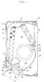
- Fig.1 is a cross sectional view of a first embodiment of the present invention.
- a cross flow blower 10 has suction ports 11 at upper side and ceiling, and has a blowing port 15 at lower side, and a draft path 13 is formed between the suction ports 11 and blowing port 12.
- a detachable air filter 16 to be inserted to the ceiling side position of a main body base frame 15, heat exchangers 17 disposed at front side and back side, and a cross flow fan 18 located inside enclosed by the heat exchangers 17 are disposed along the inner side of a front cover 14.
- the cross flow fan 18 is composed by, assembling, in the direction of the axis of rotaion, a plurality of impellers, each of which is formed by arranging plural blades 19 in a columnar form.
- a stabilizer 21 located closely and oppositely to the cross flow fan 18, and a rear guide 23 forming a diffuser 22 extending from the cross flow fan 18 to the blowing port 12 between it and the stabilizer 21 are arranged.
- Part of the rear guide 23 and stabilizer 21 forms a drain pan 24 for receiving dehumidified water dropping from the heat exchangers 17.
- the blowing port 12 comprises a vertical guide blade 25 for controlling the direction of air flow blowing out into the room in the vertical direction, and a lateral guide blade 26 for controlling in the lateral direction.
- the vertical guide blade 25 is positioned outside of the diffuser 22 in most part during normal operation.
- a coupling beam 27 which moves the lateral guide blade 26, is fitted to a coupling pin 28 for interlinking the lateral guide blade 26.
- the state of the vertical guide blade 25 during operation is indicated by solid line, and that in stopped state by twin dot chain line.
- the vertical guide blade 25 is disposed outside of the diffuser 22 by 1/2 or more of the chord length. That is, the front edge of the vertical guide blade 25 is present at a position in a distance of 1/2 or less of the chord length L from the opening end of the blowing port 12.
- M1 indicates the middle point of the chord length L of the vertical guide blade 25.
- the air flow passes through the suction ports 11, air filter 16, and heat exchangers 17, and flows into the cross flow fan 18, and further passes through the diffuser 22 formed between the rear guide 23 and stabilizer 21, and is controlled of the blowing direction by the vertical guide blade 25 and lateral guide blade 26, and is released into the room through the blowing port 12.
- the air flow blowing out of the cross flow fan 18 collides against the front edge of the vertical guide blade 25 in a state of considerably lowered flow velocity.
- no increase of noise is induced, and large peeling does not occur at the upper side and lower side of the vertical guide blade 25, and therefore a smooth flow field is formed and the flow rate performance is enhanced.
- 1/2 or more of the vertical guide blade 25 is present outside the diffuser 22, the control of running direction of air flow is more accurate.
- Fig. 2 is a cross sectional view of a second embodiment of the present invention. Members acting same as in the first embodiment are identified with same reference numerals and explanation is omitted.
- upper guide blades 31, 32 are disposed in the blowing port 12 in upper position and lower position, and the both vertical guide blades 31, 32 are disposed so that 1/2 or more of the chord length may be present outside of the diffuser 22 during normal operation.
- M2 denotes the middle point of the chord length L of the upper vertical guide blade 31
- M3 is the middle point of the chord length L of the lower vertical guide blade 32.
- the air flow blowing out of the cross flow fan 18 collides against the front edges 31a, 32a of the vertical guide blades 31a, 32a in a state of considerably lowered flow velocity.
- no increase of noise is induced, and large peeling does not occur at the upper side and lower side of the vertical guide blades 31, 32, and therefore a smooth flow field is formed and the flow rate performance is enhanced.
- the narrow passage formed between the lower vertical guide blade 32 and rear guide 23 is large in draft resistance, but since 1/2 or more of the chord length of the vertical guide blade 32 is present outside of the diffuser, the distance of narrow passage is short, and the flow rate performance does not deteriorate.
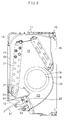
- Fig. 3 is a cross sectional view of a third embodiment of the present invention. Members acting same as in the second embodiment are identified with same reference numerals and explanation is omitted.
- vertical guide blades 41, 42 are shown in normal operation state, and the both vertical guide blades 41, 42 are disposed so that 1/2 or more of the chord length may be present outside of the diffuser 22 during normal operation.
- the vertical guide blades 41, 42 are in a wing shape, having upper sides 41a, 42a and lower sides 41b, 42b raised to the outer side in a sectional shape.
- the vertical guide blades 41, 42 are in an optimum wing shape small in draft resistance, and peeling occurring at the front edge and rear edge of the vertical guide blades 41, 42 is extremely suppressed, so that the flow rate performance may be enhanced.
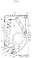
- Fig. 4 is a cross sectional view of a fourth embodiment of the present invention. Members acting same as in the second embodiment are identified with same reference numerals and explanation is omitted.
- vertical guide blades 51, 52 are shown in normal operation state, and the both vertical guide blades 51, 52 are disposed so that 1/2 or more of the chord length may be present outside of the diffuser 22 during normal operation.
- the vertical guide blades 51, 52 are shown in normal operation state.
- the vertical guide blades 51, 52 have the front edges 51a, 52a formed in an arc form in a sectional shape, and the upper sides 51b, 52b and lower sides 51c, 52c are continuous smoothly through the front edges 51a, 52a.
- Fig. 5 is a cross sectional view of a fifth embodiment of the present invention. Members acting same as in the second embodiment are identified with same reference numerals and explanation is omitted.
- vertical guide blades 61, 62 are shown in normal operation state, and the both vertical guide blades 61, 62 are disposed so that 1/2 or more of the chord length may be present outside of the diffuser 22 during normal operation.
- the vertical guide blade 61 is an oblong shape in a sectional shape
- the vertical guide blade 62 is an elliptical shape in a sectional view.
- the noise caused by collision of air flow against the leading ends of the vertical guide blades 61, 62 is further suppressed, and peeling at the upper side and lower side of the yertical guide blades 61, 62 is further suppressed, the draft resistance is decreased, and the flow rate performance is enhanced.
- the vertical guide blades are in a shape suited to mass production by resin material.
- Fig. 6 is a cross sectional view of a sixth embodiment of the present invention. Members acting same as in the second embodiment are identified with same reference numerals and explanation is omitted.
- vertical guide blades 71, 72 are shown in normal operation state, and the both vertical guide blades 71, 72 are disposed so that 1/2 or more of the chord length may be present outside of the diffuser 22 during normal operation.
- a coupling beam 73 is disposed along the stream of the air flow in the diffuser 22.
- the coupling beam 73 is located between the lower vertical guide blade 72 and rear guide 23 in the height direction of the diffuser 22, when the slope angle ⁇ of the lower vertical guide blade 72, the slope angle ⁇ in the blowing port 12 of the rear guide 23, and the slope angle ⁇ of the coupling beam 73 satisfy the following relation, the coupling beam 73 is in a position along the stream of the air flow.
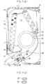
- Fig. 7 (a) and Fig. 7 (b) are cross sectional views of a seventh embodiment of the present invention. Members acting same as in the sixth embodiment are identified with same reference numerals and explanation is omitted.
- a coupling beam 81 for moving the lateral guide blade 26 by interlinking is formed in an elliptical or oblong shape in a sectional shape.
- the noise caused by the air colliding against the leading end of the front edge of the coupling beam 81 can be further suppressed, and peeling at the upper side and lower side of the coupling beam 81 can be further suppressed, and therefore the draft resistance is smaller and the flow rate performance is further enhanced.
- Fig. 8 is a cross sectional view of an eighth embodiment of the present invention. Members acting same as in the second embodiment are identified with same reference numerals and explanation is omitted.
- a coupling beam 91 is disposed at a position immediately before the upstream side of the upper vertical guide blade 31.
- the vertical guide blade 31 and coupling beam 91 act as an integral existence to the stream of air flow, and it hence suppresses the phenomena of occurrence of fluid noise and deterioration of flow rate performance due to draft resistance taking place individually in the vertical guide blade and coupling beam in the prior art.
- the noise quantity and deterioration portion of flow rate brought about by the vertical guide blade 31 and coupling beam 91 as an integral existence correspond to the noise quantity and deterioration portion of flow rate performance brought about by the vertical guide blade only in the prior art.
- Fig. 9 is a cross sectional view of a ninth embodiment of the present invention. Members acting same as in the eighth embodiment are identified with same reference numerals and explanation is omitted.
- a coupling beam 101 is disposed at a position immediately before the upstream side of the lower vertical guide blade 32.
- the vertical guide blade 32 and coupling beam 101 act as an integral existence to the stream of air flow, and it hence suppresses the phenomena of occurrence of fluid noise and deterioration of flow rate performance due to draft resistance taking place individually in the vertical guide blade and coupling beam in the prior art.
- the noise quantity and deterioration portion of flow rate brought about by the vertical guide blade 32 and coupling beam 101 as an integral existence correspond to the noise quantity and deterioration portion of flow rate performance brought about by the vertical guide blade only in the prior art.
Applications Claiming Priority (3)
| Application Number | Priority Date | Filing Date | Title |
|---|---|---|---|
| JP7234916A JPH0979601A (ja) | 1995-09-13 | 1995-09-13 | 横断流送風機 |
| JP23491695 | 1995-09-13 | ||
| EP96114662A EP0763698B1 (de) | 1995-09-13 | 1996-09-12 | Querstromlüfter |
Related Parent Applications (1)
| Application Number | Title | Priority Date | Filing Date |
|---|---|---|---|
| EP96114662A Division EP0763698B1 (de) | 1995-09-13 | 1996-09-12 | Querstromlüfter |
Publications (3)
| Publication Number | Publication Date |
|---|---|
| EP0989374A2 true EP0989374A2 (de) | 2000-03-29 |
| EP0989374A3 EP0989374A3 (de) | 2001-04-18 |
| EP0989374B1 EP0989374B1 (de) | 2004-11-24 |
Family
ID=16978302
Family Applications (2)
| Application Number | Title | Priority Date | Filing Date |
|---|---|---|---|
| EP99126029A Expired - Lifetime EP0989374B1 (de) | 1995-09-13 | 1996-09-12 | Querstromlüfter |
| EP96114662A Expired - Lifetime EP0763698B1 (de) | 1995-09-13 | 1996-09-12 | Querstromlüfter |
Family Applications After (1)
| Application Number | Title | Priority Date | Filing Date |
|---|---|---|---|
| EP96114662A Expired - Lifetime EP0763698B1 (de) | 1995-09-13 | 1996-09-12 | Querstromlüfter |
Country Status (7)
| Country | Link |
|---|---|
| EP (2) | EP0989374B1 (de) |
| JP (1) | JPH0979601A (de) |
| KR (1) | KR100408598B1 (de) |
| CN (2) | CN1080839C (de) |
| ES (2) | ES2234201T3 (de) |
| GR (1) | GR3036448T3 (de) |
| MY (1) | MY124543A (de) |
Cited By (5)
| Publication number | Priority date | Publication date | Assignee | Title |
|---|---|---|---|---|
| WO2002077539A1 (en) * | 2001-03-20 | 2002-10-03 | Aermec S.P.A. | Air-distribution cap for a convector |
| EP1380797A1 (de) * | 2002-07-12 | 2004-01-14 | Fujitsu General Limited | Klimaanlage |
| CN104296351A (zh) * | 2014-09-28 | 2015-01-21 | 美的集团武汉制冷设备有限公司 | 空调器 |
| CN109737507A (zh) * | 2018-12-20 | 2019-05-10 | 青岛海尔空调器有限总公司 | 空调器 |
| CN111795429A (zh) * | 2020-07-13 | 2020-10-20 | Tcl空调器(中山)有限公司 | 外壳组件、空调室内机以及空调器 |
Families Citing this family (19)
| Publication number | Priority date | Publication date | Assignee | Title |
|---|---|---|---|---|
| JP3277868B2 (ja) * | 1997-11-26 | 2002-04-22 | ダイキン工業株式会社 | 空気調和機の室内機 |
| KR19990080984A (ko) * | 1998-04-24 | 1999-11-15 | 윤종용 | 개선된 스태빌라이저를 가지는 횡류팬 송풍기 |
| WO2004070283A1 (en) * | 2003-02-07 | 2004-08-19 | A/S Ribe Jernindustri | Ventilating aggregate , units, system and methode including units that are easily connectable to other units and safety switch |
| JP2006078135A (ja) * | 2004-09-13 | 2006-03-23 | Matsushita Electric Ind Co Ltd | 空気調和機 |
| JP4873845B2 (ja) * | 2004-10-01 | 2012-02-08 | 三菱電機株式会社 | 空気調和機 |
| JP4513548B2 (ja) * | 2004-12-22 | 2010-07-28 | パナソニック株式会社 | 空気調和機の室内機 |
| KR100922017B1 (ko) * | 2005-07-29 | 2009-10-16 | 캐리어 코포레이션 | 증발기 유닛용 수평 루버 지지 브래킷 |
| KR101436628B1 (ko) | 2007-10-23 | 2014-09-02 | 엘지전자 주식회사 | 횡류팬 및 공기 조화기 |
| EP2405206B1 (de) * | 2009-03-06 | 2019-04-24 | Mitsubishi Electric Corporation | Klimaanlage |
| JP5518013B2 (ja) * | 2011-08-18 | 2014-06-11 | 三菱電機株式会社 | 空気調和機の室内機、及びこの室内機を備えた空気調和機 |
| JP5403131B1 (ja) * | 2012-09-28 | 2014-01-29 | ダイキン工業株式会社 | 空気調和機 |
| JP5533969B2 (ja) | 2012-09-28 | 2014-06-25 | ダイキン工業株式会社 | 空気調和機 |
| CN103851692A (zh) * | 2012-11-28 | 2014-06-11 | 珠海格力电器股份有限公司 | 空调室内机 |
| JP2015055441A (ja) * | 2013-09-13 | 2015-03-23 | パナソニック株式会社 | 空気調和機 |
| CN105971908B (zh) * | 2016-05-05 | 2018-07-06 | 四川圣锦高新科技股份有限公司 | 一种降噪引风机构以及贯流电器 |
| CN107131626B (zh) * | 2017-06-07 | 2024-01-02 | 珠海格力电器股份有限公司 | 扫风连杆、扫风机构和空调器 |
| CN108317598B (zh) * | 2018-01-05 | 2020-10-13 | 青岛海尔空调器有限总公司 | 壁挂式空调室内机 |
| CN110878962A (zh) * | 2018-08-22 | 2020-03-13 | 青岛海尔空调器有限总公司 | 异向导风结构、空调器及其出风控制方法 |
| CN110068053A (zh) * | 2019-05-27 | 2019-07-30 | 广东美的制冷设备有限公司 | 用于空调设备的导流装置及空调设备 |
Citations (4)
| Publication number | Priority date | Publication date | Assignee | Title |
|---|---|---|---|---|
| JPS59183235A (ja) * | 1983-03-31 | 1984-10-18 | Hino Motors Ltd | 空気調和装置用の空気吹出装置 |
| JPH0599492A (ja) * | 1991-10-11 | 1993-04-20 | Matsushita Electric Ind Co Ltd | 空気調和機の風向制御装置 |
| JPH06221664A (ja) * | 1993-01-28 | 1994-08-12 | Daikin Ind Ltd | 空気調和機の吹出口構造 |
| JPH07158952A (ja) * | 1993-12-07 | 1995-06-20 | Matsushita Electric Ind Co Ltd | 風向変更装置 |
Family Cites Families (6)
| Publication number | Priority date | Publication date | Assignee | Title |
|---|---|---|---|---|
| JPS57108494A (en) * | 1980-12-25 | 1982-07-06 | Matsushita Electric Ind Co Ltd | Flow direction controlling device |
| JPS57112627A (en) * | 1980-12-29 | 1982-07-13 | Mitsubishi Electric Corp | Air conditioner |
| JPH01318798A (ja) * | 1988-06-17 | 1989-12-25 | Taiheiyo Kogyo Kk | クロスフローファンの羽根車 |
| JP3036945B2 (ja) * | 1992-01-29 | 2000-04-24 | 松下電器産業株式会社 | 送風機器室外機用の吹出し口前面グリル |
| US5341650A (en) * | 1992-03-13 | 1994-08-30 | Kabushiki Kaisha Toshiba | Air conditioning apparatus having a plurality of inlets for taking in indoor air at a plurality of portions of main body thereof |
| JPH07217985A (ja) * | 1993-12-10 | 1995-08-18 | Fujitsu General Ltd | 空気調和機 |
-
1995
- 1995-09-13 JP JP7234916A patent/JPH0979601A/ja active Pending
-
1996
- 1996-09-12 EP EP99126029A patent/EP0989374B1/de not_active Expired - Lifetime
- 1996-09-12 EP EP96114662A patent/EP0763698B1/de not_active Expired - Lifetime
- 1996-09-12 KR KR1019960039575A patent/KR100408598B1/ko not_active IP Right Cessation
- 1996-09-12 ES ES99126029T patent/ES2234201T3/es not_active Expired - Lifetime
- 1996-09-12 ES ES96114662T patent/ES2158981T3/es not_active Expired - Lifetime
- 1996-09-13 MY MYPI96003803A patent/MY124543A/en unknown
- 1996-09-13 CN CN97107100A patent/CN1080839C/zh not_active Expired - Fee Related
-
2001
- 2001-08-22 CN CNB011223006A patent/CN1254642C/zh not_active Expired - Fee Related
- 2001-08-27 GR GR20010401298T patent/GR3036448T3/el not_active IP Right Cessation
Patent Citations (4)
| Publication number | Priority date | Publication date | Assignee | Title |
|---|---|---|---|---|
| JPS59183235A (ja) * | 1983-03-31 | 1984-10-18 | Hino Motors Ltd | 空気調和装置用の空気吹出装置 |
| JPH0599492A (ja) * | 1991-10-11 | 1993-04-20 | Matsushita Electric Ind Co Ltd | 空気調和機の風向制御装置 |
| JPH06221664A (ja) * | 1993-01-28 | 1994-08-12 | Daikin Ind Ltd | 空気調和機の吹出口構造 |
| JPH07158952A (ja) * | 1993-12-07 | 1995-06-20 | Matsushita Electric Ind Co Ltd | 風向変更装置 |
Non-Patent Citations (4)
| Title |
|---|
| PATENT ABSTRACTS OF JAPAN vol. 009, no. 042 (M-359), 22 February 1985 (1985-02-22) & JP 59 183235 A (HINO JIDOSHA KOGYO KK), 18 October 1984 (1984-10-18) * |
| PATENT ABSTRACTS OF JAPAN vol. 017, no. 447 (M-1464), 17 August 1993 (1993-08-17) -& JP 05 099492 A (MATSUSHITA ELECTRIC IND CO LTD), 20 April 1993 (1993-04-20) * |
| PATENT ABSTRACTS OF JAPAN vol. 018, no. 594 (M-1703), 14 November 1994 (1994-11-14) -& JP 06 221664 A (DAIKIN IND LTD), 12 August 1994 (1994-08-12) * |
| PATENT ABSTRACTS OF JAPAN vol. 1995, no. 09, 31 October 1995 (1995-10-31) -& JP 07 158952 A (MATSUSHITA ELECTRIC IND CO LTD), 20 June 1995 (1995-06-20) * |
Cited By (7)
| Publication number | Priority date | Publication date | Assignee | Title |
|---|---|---|---|---|
| WO2002077539A1 (en) * | 2001-03-20 | 2002-10-03 | Aermec S.P.A. | Air-distribution cap for a convector |
| US6921329B2 (en) | 2001-03-20 | 2005-07-26 | Aermec S.P.A. | Air-distribution cap for a convector |
| EP1380797A1 (de) * | 2002-07-12 | 2004-01-14 | Fujitsu General Limited | Klimaanlage |
| CN104296351A (zh) * | 2014-09-28 | 2015-01-21 | 美的集团武汉制冷设备有限公司 | 空调器 |
| CN104296351B (zh) * | 2014-09-28 | 2017-05-10 | 美的集团武汉制冷设备有限公司 | 空调器 |
| CN109737507A (zh) * | 2018-12-20 | 2019-05-10 | 青岛海尔空调器有限总公司 | 空调器 |
| CN111795429A (zh) * | 2020-07-13 | 2020-10-20 | Tcl空调器(中山)有限公司 | 外壳组件、空调室内机以及空调器 |
Also Published As
| Publication number | Publication date |
|---|---|
| EP0989374A3 (de) | 2001-04-18 |
| EP0763698B1 (de) | 2001-05-30 |
| CN1362585A (zh) | 2002-08-07 |
| EP0763698A1 (de) | 1997-03-19 |
| ES2234201T3 (es) | 2005-06-16 |
| GR3036448T3 (en) | 2001-11-30 |
| KR100408598B1 (ko) | 2004-03-20 |
| KR970016147A (ko) | 1997-04-28 |
| CN1254642C (zh) | 2006-05-03 |
| ES2158981T3 (es) | 2001-09-16 |
| CN1147600A (zh) | 1997-04-16 |
| CN1080839C (zh) | 2002-03-13 |
| EP0989374B1 (de) | 2004-11-24 |
| MY124543A (en) | 2006-06-30 |
| JPH0979601A (ja) | 1997-03-28 |
Similar Documents
| Publication | Publication Date | Title |
|---|---|---|
| EP0989374A2 (de) | Querstromlüfter | |
| JP2007024345A (ja) | 空気調和機 | |
| EP2607806B1 (de) | Innenraumeinheit einer Klimaanlage | |
| JP7232986B2 (ja) | 天井埋め込み形空気調和機 | |
| JPH11118233A (ja) | 空気調和装置の空気吹出口構造 | |
| US5056987A (en) | Cross flow fan system | |
| JP2000065418A (ja) | 空気調和機 | |
| EP1703217A1 (de) | Klimaanlage | |
| EP0962716B1 (de) | Klimaanlage | |
| EP2280176B1 (de) | Querstromlüfter und klimaanlage damit | |
| EP0928899B1 (de) | Querstromlüfter | |
| JPH07117066B2 (ja) | 横流ファン装置 | |
| JP2003329295A (ja) | 空調装置のルーバー及び空調装置の気流制御構造、並びに空調装置 | |
| JP2000120582A (ja) | 遠心送風機 | |
| JPH0670519B2 (ja) | 空気調和機の風向偏向装置 | |
| JPH0416105Y2 (de) | ||
| JP4698818B2 (ja) | 多翼送風機 | |
| JP4866643B2 (ja) | デフロスタ用送風ダクト | |
| JP3526156B2 (ja) | 空気調和機の風向制御装置及び天井カセット形空気調和機の風向制御方法 | |
| JPH1019291A (ja) | 壁掛け式空気調和装置 | |
| JP2689802B2 (ja) | 空気調和機 | |
| JP3632117B2 (ja) | 空気調和機 | |
| JPH08189671A (ja) | 空気調和装置の室外機 | |
| JPS6120720B2 (de) | ||
| JPH06307711A (ja) | 空気調和装置 |
Legal Events
| Date | Code | Title | Description |
|---|---|---|---|
| PUAI | Public reference made under article 153(3) epc to a published international application that has entered the european phase |
Free format text: ORIGINAL CODE: 0009012 |
|
| 17P | Request for examination filed |
Effective date: 19991227 |
|
| AC | Divisional application: reference to earlier application |
Ref document number: 763698 Country of ref document: EP |
|
| AK | Designated contracting states |
Kind code of ref document: A2 Designated state(s): ES GR IT |
|
| PUAL | Search report despatched |
Free format text: ORIGINAL CODE: 0009013 |
|
| AK | Designated contracting states |
Kind code of ref document: A3 Designated state(s): ES GR IT |
|
| AKX | Designation fees paid |
Free format text: ES GR IT |
|
| 17Q | First examination report despatched |
Effective date: 20030604 |
|
| GRAP | Despatch of communication of intention to grant a patent |
Free format text: ORIGINAL CODE: EPIDOSNIGR1 |
|
| GRAS | Grant fee paid |
Free format text: ORIGINAL CODE: EPIDOSNIGR3 |
|
| GRAA | (expected) grant |
Free format text: ORIGINAL CODE: 0009210 |
|
| AC | Divisional application: reference to earlier application |
Ref document number: 0763698 Country of ref document: EP Kind code of ref document: P |
|
| AK | Designated contracting states |
Kind code of ref document: B1 Designated state(s): ES GR IT |
|
| REG | Reference to a national code |
Ref country code: GR Ref legal event code: EP Ref document number: 20050400331 Country of ref document: GR |
|
| REG | Reference to a national code |
Ref country code: ES Ref legal event code: FG2A Ref document number: 2234201 Country of ref document: ES Kind code of ref document: T3 |
|
| PLBE | No opposition filed within time limit |
Free format text: ORIGINAL CODE: 0009261 |
|
| STAA | Information on the status of an ep patent application or granted ep patent |
Free format text: STATUS: NO OPPOSITION FILED WITHIN TIME LIMIT |
|
| 26N | No opposition filed |
Effective date: 20050825 |
|
| PGFP | Annual fee paid to national office [announced via postgrant information from national office to epo] |
Ref country code: IT Payment date: 20070926 Year of fee payment: 12 Ref country code: ES Payment date: 20071005 Year of fee payment: 12 |
|
| PGFP | Annual fee paid to national office [announced via postgrant information from national office to epo] |
Ref country code: GR Payment date: 20070820 Year of fee payment: 12 |
|
| PG25 | Lapsed in a contracting state [announced via postgrant information from national office to epo] |
Ref country code: IT Free format text: LAPSE BECAUSE OF NON-PAYMENT OF DUE FEES Effective date: 20080912 |
|
| REG | Reference to a national code |
Ref country code: ES Ref legal event code: FD2A Effective date: 20080913 |
|
| PG25 | Lapsed in a contracting state [announced via postgrant information from national office to epo] |
Ref country code: GR Free format text: LAPSE BECAUSE OF NON-PAYMENT OF DUE FEES Effective date: 20090402 |
|
| PG25 | Lapsed in a contracting state [announced via postgrant information from national office to epo] |
Ref country code: ES Free format text: LAPSE BECAUSE OF NON-PAYMENT OF DUE FEES Effective date: 20080913 |