EP0989268A1 - Mechanismus für die Bewegungsübertragung eines Türgriffs oder Schlüssels zu einem Riegelverschluss eines Schlosses - Google Patents
Mechanismus für die Bewegungsübertragung eines Türgriffs oder Schlüssels zu einem Riegelverschluss eines Schlosses Download PDFInfo
- Publication number
- EP0989268A1 EP0989268A1 EP99660139A EP99660139A EP0989268A1 EP 0989268 A1 EP0989268 A1 EP 0989268A1 EP 99660139 A EP99660139 A EP 99660139A EP 99660139 A EP99660139 A EP 99660139A EP 0989268 A1 EP0989268 A1 EP 0989268A1
- Authority
- EP
- European Patent Office
- Prior art keywords
- lock
- locking bar
- locking
- door handle
- movement
- Prior art date
- Legal status (The legal status is an assumption and is not a legal conclusion. Google has not performed a legal analysis and makes no representation as to the accuracy of the status listed.)
- Granted
Links
Images


Classifications
-
- E—FIXED CONSTRUCTIONS
- E05—LOCKS; KEYS; WINDOW OR DOOR FITTINGS; SAFES
- E05B—LOCKS; ACCESSORIES THEREFOR; HANDCUFFS
- E05B65/00—Locks or fastenings for special use
- E05B65/10—Locks or fastenings for special use for panic or emergency doors
- E05B65/1046—Panic bars
- E05B65/106—Panic bars pivoting
- E05B65/1066—Panic bars pivoting the pivot axis being substantially parallel to the longitudinal axis of the bar
-
- E—FIXED CONSTRUCTIONS
- E05—LOCKS; KEYS; WINDOW OR DOOR FITTINGS; SAFES
- E05B—LOCKS; ACCESSORIES THEREFOR; HANDCUFFS
- E05B7/00—Handles pivoted about an axis parallel to the wing
Definitions
- the present invention relates to a mechanism for transmission of movement of a door handle or a key to the locking bolt of a lock according to the preamble of claim 1 presented below.
- the objective of the invention is to provide an enhanced mechanism for the transmission of movement of a key or a door handle in which the above problems have been eliminated or at least minimised.
- the aim of the invention is to provide a mechanism, that enables, when opening with a key, a transmission ratio between the turning movement of the key and the movement of the locking bolt of the lock, whereby sufficient force is provided for opening the lock without any problems.
- the mechanism of the invention is characterised by what is determined in the characteristic features' part of independent claim 1 below.
- the mechanism of the invention comprises typically a separate body provided with a locking bar member.
- the locking bar member is comprised of two locking bars, axially deflected aside relative to each other but substantially parallel in direction and operatively connected to each other with cogwheels of different sizes and rotating about their longitudinal axes, the first of said locking bars being connectable to the cylinder body or the door handle and the second to the lock body and the locking bolt of the lock.
- the transmission ratio of the movement opening the lock and of the movement of the locking bolt can be selected for each purpose by changing the cogwheels. Also the positioning of the cylinder body or the door opening handle in the door can be selected according to the purpose.
- the opening of the lock can be enabled even using minor movement of the door handle.
- the transmission mechanism of the invention also enables the positioning of the door handle as appropriately as possible, for instance in exits, to be at a distance from the door jamb and in upright position on an edge of the door, thus enabling opening without any problems also from floor level (e.g. in a fire or a gas leak).
- the transmission mechanism comprises a body separate from the lock body, with two substantially parallel locking bars.
- the first locking bar can be connected to the cylinder body or the door handle by means of an idler sheave in conjunction therewith.
- the other locking bar protrudes from the body of the transmission mechanism to the body of the lock, therethrough being connectable with the locking bolt of the lock.
- the mechanism of the invention can be connected to any lock whatsoever as long as it can be carried out so that the movement of one of the locking bars of the mechanism is transmitted to the locking bolt of the lock.
- old locks in which the movement of the key and/or the door handle is not, considering their purpose, advantageously transmitted to the locking bolt of the lock, can be provided with a transmission mechanism according to the invention and therethrough the advantages of the invention can be achieved even without having to replace the original lock body.
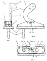
- the mechanism of the invention comprises a mainly rectangular body 4, consisting of a cover 4' and an intermediate piece 4" and a bottom 4'''.
- the body pieces 4', 4", 4''' have been so designed that they can be piled one on top of the other to form a substantially congruent element.
- the cover 4' and the bottom 4''' are provided with three consecutive apertures 10', 10"', these being placeable in concentric position relative to one another.
- the intermediate piece includes an aperture 10" greater in size than the apertures 10', 10''' of the bottom 4''' and the cover 4'.
- the cogwheels 6 and 8 of the locking bar member of the invention have been placed in aperture 10" of the intermediate piece 4" between the cover 4' and the bottom 4''' so that the arms 16 of the top and bottom surfaces of the cogwheels, round in cross-section, are placed accurately at the respective concentric, round apertures 10' and 10''' of the cover 4' and the bottom 4''', and that the cogwheels are appropriately in conjunction with each other to bring about the transmission movement.
- the arms 16 of the cogwheel 6, the cogwheel being operatively connected to the door handle 22 or the cylinder body have each time been adapted to the centremost round apertures 10' and 10'''.
- the cogwheel 8, connected operatively with the lock body 20, can be adapted to be located on either side of the cogwheel 6 as long as the intermediate piece 4" is so turned that its oval aperture 10" is set in the end of the body 4 on which cogwheel 8 is desired to be disposed.
- the aperture 10" of the intermediate piece 4" can also be made so ample that the intermediate piece 4" need not be turned when wishing to dispose cogwheel 6 on the other side of cogwheel 8.
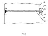
- the door handle 22 in the present embodiment is, as can be seen in Figure 1, a rod extending transversely across the door 23, said rod being also at the other end attached pivotably to the door 23.
- the door handle can also be disposed to be substantially vertical to the door 23 and extended down to the extent that opening the door, for instance in a fire, is possible on the floor level where the smoke and the heat reach last.
- Cogwheel 6 can be turned with a key, instead of the movement of the door handle 22, if the key has by transmission of the cylinder body and, possibly also, of the locking bar 12 been connected operatively to cogwheel 6.
- the pivoted arm 30 rotates the idler sheave 14 on the first locking bar 6. Since the ends of the shaft 26 are supported by the oval apertures 28, the contact surface between the pivoted arm 30 and the idler sheave 14 and additionally the contact surface of the slide arm 32 and the idler sheave 14, said contact surface being on the opposite side of the pivoted arm 12 on the idler sheave 14, become the supporting points of the movement of the pivoted arm 30 turning the idler sheave 14.
- the movement is transmitted to the first locking bar 12 advantageously in this embodiment because the force directed at the door handle 22 is so divided that the pivoted arm 30 and the slide arm 32 rotate the idler sheave 14 from both sides of the locking bar 12 in the same direction and at equal force, whereby the friction between the moving parts is at its minimum.
- the movement is transmitted to the second locking bar 18 by transmission of the cogwheel 6 of the first locking bar 12 and the cogwheel 8 of the second locking bar 18 operatively connected therewith.
- the first cogwheel 6 to be greater in diameter than the second cogwheel 8
- the second locking bar 18 can be made to rotate more than the first locking bar 12 and, using a small movement of the door handle, a greater rotary movement for opening the locking bolt 34 of the lock 20 can be provided to the second locking bar 18.
- first cogwheel 6 By selecting the first cogwheel 6 to be smaller in diameter than the second cogwheel 8, a greater rotary movement of the first locking bar 12 to rotate the second locking bar 18 is needed to open the locking bolt 34 of the lock 20 and respectively, a greater movement of the door handle 22 or the turning movement of the key, if the turning movement of the key rotates the first locking bar 12 by transmission of the cylinder body.
- the transmission ratio of the cogwheels 6 and 8 may, depending on the purpose, be e.g. in the range 1/4 to 4/1.
- the cogwheels 6 and 8 are detachable from the locking bars 12 and 18, square in cross-section, so that by changing the cogwheel sizes, the transmission between the locking bars can be changed. Be it that the locking bars 12 and 18 may be of other cross-sections than rectangular, they are, however, typically angular in shape.
- the shape of the central apertures in the cogwheels 6 and 8 and in the idler sheave 14 is selected to comply with the shape of the locking bar.
- the door handle or the cylinder body intended to be used when opening according to the invention, can be disposed in any desired direction by the distance between the locking bars 12 and 18 from the opening locking bar 18 in order to obtain the most advantageous location, for instance at a distance away from any obstructions by door jambs possibly inhibiting the movement of the door handle.
- a lock to be opened primarily with a door handle is described.
- a lock opened with a key is mentioned, and an advantage is in such an instance gained with a transmission with which the rotary movement of the key is enlarged compared with the rotary movement of the locking bar opening the locking bolt, in order to have sufficient force for opening the lock in any situation.
- the mechanism of the invention can be used in exits, such as in exits of dwelling houses, public premises, places of work and ships.
- the locks of the exit doors are to be relatively easy to open in any circumstances, and therefore, a plurality of authority regulations regulate the properties affecting said aspect. It is of importance that the exit doors can be opened at a given minimum force, also in situations in which forces inhibiting the opening exert an impact on the doors.
- An advantage of the present invention lies in that the mechanism of the invention can quite often be mounted on a lock of an existing exit door without having to make significant changes in the door or in the lock body; instead, it is enough that the mechanism of the invention is disposed between the door handle intended for opening and the lock body.
Landscapes
- Business, Economics & Management (AREA)
- Emergency Management (AREA)
- Lock And Its Accessories (AREA)
- Endoscopes (AREA)
- Special Wing (AREA)
- Switches With Compound Operations (AREA)
- Mechanical Control Devices (AREA)
- Driving Mechanisms And Operating Circuits Of Arc-Extinguishing High-Tension Switches (AREA)
Applications Claiming Priority (2)
| Application Number | Priority Date | Filing Date | Title |
|---|---|---|---|
| FI981889 | 1998-09-04 | ||
| FI981889A FI107557B (fi) | 1998-09-04 | 1998-09-04 | Lukon telkeen avaimen tai painikkeen liikkeen välittävä mekanismi ja sen käyttö |
Publications (2)
| Publication Number | Publication Date |
|---|---|
| EP0989268A1 true EP0989268A1 (de) | 2000-03-29 |
| EP0989268B1 EP0989268B1 (de) | 2003-04-16 |
Family
ID=8552414
Family Applications (1)
| Application Number | Title | Priority Date | Filing Date |
|---|---|---|---|
| EP99660139A Expired - Lifetime EP0989268B1 (de) | 1998-09-04 | 1999-09-03 | Mechanismus für die Bewegungsübertragung eines Türgriffs oder Schlüssels zu einem Riegelverschluss eines Schlosses |
Country Status (4)
| Country | Link |
|---|---|
| EP (1) | EP0989268B1 (de) |
| AT (1) | ATE237725T1 (de) |
| DE (1) | DE69906899D1 (de) |
| FI (1) | FI107557B (de) |
Cited By (6)
| Publication number | Priority date | Publication date | Assignee | Title |
|---|---|---|---|---|
| EP1764462A2 (de) | 2005-09-19 | 2007-03-21 | Hewi Heinrich Wilke Gmbh | Getriebe für eine Panikstange |
| EP2218849A3 (de) * | 2009-02-17 | 2011-09-14 | Andreas Wagner | Handhabe für Dreh-Kipp-Fenster und Dreh-Kipp-Türen |
| WO2014041135A1 (de) * | 2012-09-13 | 2014-03-20 | Assa Abloy Sicherheitstechnik Gmbh | Beschlag mit betätigungshandhabe für eine tür, fenster oder dergleichen mit adapterlagerplatte |
| FR3027936A1 (fr) * | 2014-10-30 | 2016-05-06 | Assa Abloy Aube Anjou | Dispositif de manoeuvre de porte a blocage electrique |
| EP3643857A1 (de) * | 2018-10-23 | 2020-04-29 | Exit-Painike Ky | Anordnung zur bewegungsübertragung |
| DE102012101458B4 (de) * | 2012-02-23 | 2020-07-30 | Herbert Viehhauser | Betätigungsanordnung für eine Tür |
Families Citing this family (1)
| Publication number | Priority date | Publication date | Assignee | Title |
|---|---|---|---|---|
| AU2021221534A1 (en) * | 2021-08-24 | 2023-03-16 | AMS Australia Pty Ltd | Dual lock actuator |
Citations (4)
| Publication number | Priority date | Publication date | Assignee | Title |
|---|---|---|---|---|
| DE3213668A1 (de) * | 1982-04-14 | 1983-10-27 | Wilh. Schlechtendahl & Söhne GmbH & Co KG, 5628 Heiligenhaus | Vorrichtung zum oeffnen von paniktueren |
| DE4400473A1 (de) * | 1993-01-13 | 1994-07-14 | Parys Remi E Van | Schloßmechanismus und mit einem derartigen Schloßmechanismus versehenes Schloß |
| CH685638A5 (de) * | 1992-06-02 | 1995-08-31 | Eichholzer Ag M | Panikbetätigung für Sicherheitsschliessvorrichtung. |
| US5547235A (en) * | 1992-01-17 | 1996-08-20 | Hewi Heinrich Wilke Gmbh | Gearing for a door lock, in particular for a panic or smoke-protection door lock |
-
1998
- 1998-09-04 FI FI981889A patent/FI107557B/fi not_active IP Right Cessation
-
1999
- 1999-09-03 DE DE69906899T patent/DE69906899D1/de not_active Expired - Lifetime
- 1999-09-03 AT AT99660139T patent/ATE237725T1/de not_active IP Right Cessation
- 1999-09-03 EP EP99660139A patent/EP0989268B1/de not_active Expired - Lifetime
Patent Citations (4)
| Publication number | Priority date | Publication date | Assignee | Title |
|---|---|---|---|---|
| DE3213668A1 (de) * | 1982-04-14 | 1983-10-27 | Wilh. Schlechtendahl & Söhne GmbH & Co KG, 5628 Heiligenhaus | Vorrichtung zum oeffnen von paniktueren |
| US5547235A (en) * | 1992-01-17 | 1996-08-20 | Hewi Heinrich Wilke Gmbh | Gearing for a door lock, in particular for a panic or smoke-protection door lock |
| CH685638A5 (de) * | 1992-06-02 | 1995-08-31 | Eichholzer Ag M | Panikbetätigung für Sicherheitsschliessvorrichtung. |
| DE4400473A1 (de) * | 1993-01-13 | 1994-07-14 | Parys Remi E Van | Schloßmechanismus und mit einem derartigen Schloßmechanismus versehenes Schloß |
Cited By (9)
| Publication number | Priority date | Publication date | Assignee | Title |
|---|---|---|---|---|
| EP1764462A2 (de) | 2005-09-19 | 2007-03-21 | Hewi Heinrich Wilke Gmbh | Getriebe für eine Panikstange |
| DE102005044680A1 (de) * | 2005-09-19 | 2007-03-22 | Hewi Heinrich Wilke Gmbh | Getriebe für eine Panikstange |
| EP1764462A3 (de) * | 2005-09-19 | 2008-09-24 | Hewi Heinrich Wilke Gmbh | Getriebe für eine Panikstange |
| EP2218849A3 (de) * | 2009-02-17 | 2011-09-14 | Andreas Wagner | Handhabe für Dreh-Kipp-Fenster und Dreh-Kipp-Türen |
| DE102012101458B4 (de) * | 2012-02-23 | 2020-07-30 | Herbert Viehhauser | Betätigungsanordnung für eine Tür |
| WO2014041135A1 (de) * | 2012-09-13 | 2014-03-20 | Assa Abloy Sicherheitstechnik Gmbh | Beschlag mit betätigungshandhabe für eine tür, fenster oder dergleichen mit adapterlagerplatte |
| FR3027936A1 (fr) * | 2014-10-30 | 2016-05-06 | Assa Abloy Aube Anjou | Dispositif de manoeuvre de porte a blocage electrique |
| EP3023562A1 (de) * | 2014-10-30 | 2016-05-25 | Assa Abloy Aube Anjou | Türbewegungsvorrichtung mit elektrischer blockierung |
| EP3643857A1 (de) * | 2018-10-23 | 2020-04-29 | Exit-Painike Ky | Anordnung zur bewegungsübertragung |
Also Published As
| Publication number | Publication date |
|---|---|
| FI981889A (fi) | 2000-03-05 |
| FI107557B (fi) | 2001-08-31 |
| EP0989268B1 (de) | 2003-04-16 |
| ATE237725T1 (de) | 2003-05-15 |
| FI981889A0 (fi) | 1998-09-04 |
| DE69906899D1 (de) | 2003-05-22 |
Similar Documents
| Publication | Publication Date | Title |
|---|---|---|
| US4759576A (en) | Adjustable deadlatch | |
| US7261330B1 (en) | Sliding door latch assembly | |
| EP0989268B1 (de) | Mechanismus für die Bewegungsübertragung eines Türgriffs oder Schlüssels zu einem Riegelverschluss eines Schlosses | |
| CA2190191C (en) | Interlock device | |
| US6962375B2 (en) | Rotary latches | |
| US4468943A (en) | Live bolt lock mechanism for safe door | |
| RU2277160C2 (ru) | Установочное устройство для управления действием ручки в дверном замке и дверной замок с таким установочным устройством | |
| US4902057A (en) | Adjustable deadlatch | |
| RU2280140C2 (ru) | Устройство соленоида для управления работой ручки дверного замка | |
| US5492380A (en) | Door latch operating assembly | |
| AU773224B2 (en) | A folding hancle | |
| US6363761B1 (en) | Modular rod locking system | |
| JPH11287058A (ja) | 扉等の中に装着されるロックケーシング | |
| KR960022063A (ko) | 핸들세트 | |
| EP1195484B1 (de) | Verschlusseinrichtung | |
| EP2944748B1 (de) | Verschlussanordnung für ein entlüftungsfenster | |
| US8297665B2 (en) | Snap-action closure suitable for a thin-walled cabinet | |
| EP0428196B1 (de) | Drehtür | |
| US5040386A (en) | Antipanic lock with a safety-drum | |
| AU2002236047B2 (en) | Improvements in mortice latches | |
| ATE121157T1 (de) | Mit schlosseinrichtung versehener versenkbarer schwenkhebelverschluss. | |
| AU2002236047A1 (en) | Improvements in mortice latches | |
| JP2005306134A (ja) | グローブボックス構造 | |
| FI130135B (en) | Arrangement for transfer of motion | |
| KR200410948Y1 (ko) | 양면 프라이팬 |
Legal Events
| Date | Code | Title | Description |
|---|---|---|---|
| PUAI | Public reference made under article 153(3) epc to a published international application that has entered the european phase |
Free format text: ORIGINAL CODE: 0009012 |
|
| AK | Designated contracting states |
Kind code of ref document: A1 Designated state(s): AT BE CH CY DE DK ES FI FR GB GR IE IT LI LU MC NL PT SE |
|
| AX | Request for extension of the european patent |
Free format text: AL;LT;LV;MK;RO;SI |
|
| 17P | Request for examination filed |
Effective date: 20000714 |
|
| AKX | Designation fees paid |
Free format text: AT BE CH CY DE DK ES FI FR GB GR IE IT LI LU MC NL PT SE |
|
| 17Q | First examination report despatched |
Effective date: 20010514 |
|
| GRAH | Despatch of communication of intention to grant a patent |
Free format text: ORIGINAL CODE: EPIDOS IGRA |
|
| GRAH | Despatch of communication of intention to grant a patent |
Free format text: ORIGINAL CODE: EPIDOS IGRA |
|
| GRAA | (expected) grant |
Free format text: ORIGINAL CODE: 0009210 |
|
| AK | Designated contracting states |
Designated state(s): AT BE CH CY DE DK ES FI FR GB GR IE IT LI LU MC NL PT SE |
|
| PG25 | Lapsed in a contracting state [announced via postgrant information from national office to epo] |
Ref country code: NL Free format text: LAPSE BECAUSE OF FAILURE TO SUBMIT A TRANSLATION OF THE DESCRIPTION OR TO PAY THE FEE WITHIN THE PRESCRIBED TIME-LIMIT Effective date: 20030416 Ref country code: LI Free format text: LAPSE BECAUSE OF FAILURE TO SUBMIT A TRANSLATION OF THE DESCRIPTION OR TO PAY THE FEE WITHIN THE PRESCRIBED TIME-LIMIT Effective date: 20030416 Ref country code: IT Free format text: LAPSE BECAUSE OF FAILURE TO SUBMIT A TRANSLATION OF THE DESCRIPTION OR TO PAY THE FEE WITHIN THE PRESCRIBED TIME-LIMIT;WARNING: LAPSES OF ITALIAN PATENTS WITH EFFECTIVE DATE BEFORE 2007 MAY HAVE OCCURRED AT ANY TIME BEFORE 2007. THE CORRECT EFFECTIVE DATE MAY BE DIFFERENT FROM THE ONE RECORDED. Effective date: 20030416 Ref country code: FR Free format text: LAPSE BECAUSE OF FAILURE TO SUBMIT A TRANSLATION OF THE DESCRIPTION OR TO PAY THE FEE WITHIN THE PRESCRIBED TIME-LIMIT Effective date: 20030416 Ref country code: FI Free format text: LAPSE BECAUSE OF FAILURE TO SUBMIT A TRANSLATION OF THE DESCRIPTION OR TO PAY THE FEE WITHIN THE PRESCRIBED TIME-LIMIT Effective date: 20030416 Ref country code: CH Free format text: LAPSE BECAUSE OF FAILURE TO SUBMIT A TRANSLATION OF THE DESCRIPTION OR TO PAY THE FEE WITHIN THE PRESCRIBED TIME-LIMIT Effective date: 20030416 Ref country code: BE Free format text: LAPSE BECAUSE OF FAILURE TO SUBMIT A TRANSLATION OF THE DESCRIPTION OR TO PAY THE FEE WITHIN THE PRESCRIBED TIME-LIMIT Effective date: 20030416 Ref country code: AT Free format text: LAPSE BECAUSE OF FAILURE TO SUBMIT A TRANSLATION OF THE DESCRIPTION OR TO PAY THE FEE WITHIN THE PRESCRIBED TIME-LIMIT Effective date: 20030416 |
|
| REG | Reference to a national code |
Ref country code: GB Ref legal event code: FG4D |
|
| REG | Reference to a national code |
Ref country code: CH Ref legal event code: EP |
|
| REF | Corresponds to: |
Ref document number: 69906899 Country of ref document: DE Date of ref document: 20030522 Kind code of ref document: P |
|
| REG | Reference to a national code |
Ref country code: IE Ref legal event code: FG4D |
|
| PG25 | Lapsed in a contracting state [announced via postgrant information from national office to epo] |
Ref country code: SE Free format text: LAPSE BECAUSE OF FAILURE TO SUBMIT A TRANSLATION OF THE DESCRIPTION OR TO PAY THE FEE WITHIN THE PRESCRIBED TIME-LIMIT Effective date: 20030716 Ref country code: PT Free format text: LAPSE BECAUSE OF FAILURE TO SUBMIT A TRANSLATION OF THE DESCRIPTION OR TO PAY THE FEE WITHIN THE PRESCRIBED TIME-LIMIT Effective date: 20030716 Ref country code: GR Free format text: LAPSE BECAUSE OF FAILURE TO SUBMIT A TRANSLATION OF THE DESCRIPTION OR TO PAY THE FEE WITHIN THE PRESCRIBED TIME-LIMIT Effective date: 20030716 Ref country code: DK Free format text: LAPSE BECAUSE OF FAILURE TO SUBMIT A TRANSLATION OF THE DESCRIPTION OR TO PAY THE FEE WITHIN THE PRESCRIBED TIME-LIMIT Effective date: 20030716 |
|
| PG25 | Lapsed in a contracting state [announced via postgrant information from national office to epo] |
Ref country code: DE Free format text: LAPSE BECAUSE OF FAILURE TO SUBMIT A TRANSLATION OF THE DESCRIPTION OR TO PAY THE FEE WITHIN THE PRESCRIBED TIME-LIMIT Effective date: 20030717 |
|
| PG25 | Lapsed in a contracting state [announced via postgrant information from national office to epo] |
Ref country code: LU Free format text: LAPSE BECAUSE OF NON-PAYMENT OF DUE FEES Effective date: 20030903 Ref country code: IE Free format text: LAPSE BECAUSE OF NON-PAYMENT OF DUE FEES Effective date: 20030903 Ref country code: CY Free format text: LAPSE BECAUSE OF FAILURE TO SUBMIT A TRANSLATION OF THE DESCRIPTION OR TO PAY THE FEE WITHIN THE PRESCRIBED TIME-LIMIT Effective date: 20030903 |
|
| PG25 | Lapsed in a contracting state [announced via postgrant information from national office to epo] |
Ref country code: MC Free format text: LAPSE BECAUSE OF NON-PAYMENT OF DUE FEES Effective date: 20030930 |
|
| NLV1 | Nl: lapsed or annulled due to failure to fulfill the requirements of art. 29p and 29m of the patents act | ||
| PG25 | Lapsed in a contracting state [announced via postgrant information from national office to epo] |
Ref country code: ES Free format text: LAPSE BECAUSE OF FAILURE TO SUBMIT A TRANSLATION OF THE DESCRIPTION OR TO PAY THE FEE WITHIN THE PRESCRIBED TIME-LIMIT Effective date: 20031030 |
|
| REG | Reference to a national code |
Ref country code: CH Ref legal event code: PL |
|
| PLBE | No opposition filed within time limit |
Free format text: ORIGINAL CODE: 0009261 |
|
| STAA | Information on the status of an ep patent application or granted ep patent |
Free format text: STATUS: NO OPPOSITION FILED WITHIN TIME LIMIT |
|
| 26N | No opposition filed |
Effective date: 20040119 |
|
| EN | Fr: translation not filed | ||
| REG | Reference to a national code |
Ref country code: IE Ref legal event code: MM4A |
|
| PGFP | Annual fee paid to national office [announced via postgrant information from national office to epo] |
Ref country code: GB Payment date: 20160923 Year of fee payment: 18 |
|
| GBPC | Gb: european patent ceased through non-payment of renewal fee |
Effective date: 20170903 |
|
| PG25 | Lapsed in a contracting state [announced via postgrant information from national office to epo] |
Ref country code: GB Free format text: LAPSE BECAUSE OF NON-PAYMENT OF DUE FEES Effective date: 20170903 |