EP0988484B1 - Drosselventil zum nachfüllen von wasserbrunnen - Google Patents
Drosselventil zum nachfüllen von wasserbrunnen Download PDFInfo
- Publication number
- EP0988484B1 EP0988484B1 EP98926407A EP98926407A EP0988484B1 EP 0988484 B1 EP0988484 B1 EP 0988484B1 EP 98926407 A EP98926407 A EP 98926407A EP 98926407 A EP98926407 A EP 98926407A EP 0988484 B1 EP0988484 B1 EP 0988484B1
- Authority
- EP
- European Patent Office
- Prior art keywords
- valve
- water
- recharge
- flow
- hydraulic
- Prior art date
- Legal status (The legal status is an assumption and is not a legal conclusion. Google has not performed a legal analysis and makes no representation as to the accuracy of the status listed.)
- Expired - Lifetime
Links
- XLYOFNOQVPJJNP-UHFFFAOYSA-N water Substances O XLYOFNOQVPJJNP-UHFFFAOYSA-N 0.000 title claims abstract description 65
- 239000012530 fluid Substances 0.000 claims description 20
- 239000003112 inhibitor Substances 0.000 claims description 6
- 230000007423 decrease Effects 0.000 claims description 3
- 230000008878 coupling Effects 0.000 claims 2
- 238000010168 coupling process Methods 0.000 claims 2
- 238000005859 coupling reaction Methods 0.000 claims 2
- 238000003860 storage Methods 0.000 abstract description 18
- 238000011084 recovery Methods 0.000 abstract description 12
- 238000002347 injection Methods 0.000 abstract description 11
- 239000007924 injection Substances 0.000 abstract description 11
- 150000003839 salts Chemical class 0.000 abstract description 4
- 230000035699 permeability Effects 0.000 abstract description 3
- 229910021532 Calcite Inorganic materials 0.000 abstract description 2
- 230000004888 barrier function Effects 0.000 abstract description 2
- 230000015572 biosynthetic process Effects 0.000 abstract description 2
- 230000009467 reduction Effects 0.000 abstract description 2
- 238000012544 monitoring process Methods 0.000 description 7
- DNIAPMSPPWPWGF-UHFFFAOYSA-N Propylene glycol Chemical compound CC(O)CO DNIAPMSPPWPWGF-UHFFFAOYSA-N 0.000 description 3
- 230000001276 controlling effect Effects 0.000 description 3
- 239000013505 freshwater Substances 0.000 description 3
- 239000003673 groundwater Substances 0.000 description 3
- 238000005086 pumping Methods 0.000 description 3
- 230000001105 regulatory effect Effects 0.000 description 3
- 230000008901 benefit Effects 0.000 description 2
- 230000001627 detrimental effect Effects 0.000 description 2
- 238000009434 installation Methods 0.000 description 2
- 238000004519 manufacturing process Methods 0.000 description 2
- 230000002829 reductive effect Effects 0.000 description 2
- 230000001932 seasonal effect Effects 0.000 description 2
- 230000003068 static effect Effects 0.000 description 2
- 229910000831 Steel Inorganic materials 0.000 description 1
- 230000009471 action Effects 0.000 description 1
- 230000002411 adverse Effects 0.000 description 1
- 230000003466 anti-cipated effect Effects 0.000 description 1
- 230000000903 blocking effect Effects 0.000 description 1
- 230000006378 damage Effects 0.000 description 1
- 230000003247 decreasing effect Effects 0.000 description 1
- 230000000994 depressogenic effect Effects 0.000 description 1
- 238000009826 distribution Methods 0.000 description 1
- 238000005553 drilling Methods 0.000 description 1
- 239000003651 drinking water Substances 0.000 description 1
- 235000020188 drinking water Nutrition 0.000 description 1
- 230000009977 dual effect Effects 0.000 description 1
- 230000005611 electricity Effects 0.000 description 1
- 238000005516 engineering process Methods 0.000 description 1
- 230000007613 environmental effect Effects 0.000 description 1
- 239000002360 explosive Substances 0.000 description 1
- 230000012010 growth Effects 0.000 description 1
- 230000002452 interceptive effect Effects 0.000 description 1
- 239000000463 material Substances 0.000 description 1
- 238000000034 method Methods 0.000 description 1
- 230000000116 mitigating effect Effects 0.000 description 1
- 238000005067 remediation Methods 0.000 description 1
- 238000009420 retrofitting Methods 0.000 description 1
- 239000010959 steel Substances 0.000 description 1
- 238000004659 sterilization and disinfection Methods 0.000 description 1
- 239000008400 supply water Substances 0.000 description 1
- 238000011282 treatment Methods 0.000 description 1
Images


Classifications
-
- E—FIXED CONSTRUCTIONS
- E21—EARTH OR ROCK DRILLING; MINING
- E21B—EARTH OR ROCK DRILLING; OBTAINING OIL, GAS, WATER, SOLUBLE OR MELTABLE MATERIALS OR A SLURRY OF MINERALS FROM WELLS
- E21B34/00—Valve arrangements for boreholes or wells
- E21B34/06—Valve arrangements for boreholes or wells in wells
- E21B34/10—Valve arrangements for boreholes or wells in wells operated by control fluid supplied from outside the borehole
- E21B34/102—Valve arrangements for boreholes or wells in wells operated by control fluid supplied from outside the borehole with means for locking the closing element in open or closed position
-
- E—FIXED CONSTRUCTIONS
- E21—EARTH OR ROCK DRILLING; MINING
- E21B—EARTH OR ROCK DRILLING; OBTAINING OIL, GAS, WATER, SOLUBLE OR MELTABLE MATERIALS OR A SLURRY OF MINERALS FROM WELLS
- E21B34/00—Valve arrangements for boreholes or wells
- E21B34/16—Control means therefor being outside the borehole
-
- E—FIXED CONSTRUCTIONS
- E21—EARTH OR ROCK DRILLING; MINING
- E21B—EARTH OR ROCK DRILLING; OBTAINING OIL, GAS, WATER, SOLUBLE OR MELTABLE MATERIALS OR A SLURRY OF MINERALS FROM WELLS
- E21B2200/00—Special features related to earth drilling for obtaining oil, gas or water
- E21B2200/02—Down-hole chokes or valves for variably regulating fluid flow
-
- Y—GENERAL TAGGING OF NEW TECHNOLOGICAL DEVELOPMENTS; GENERAL TAGGING OF CROSS-SECTIONAL TECHNOLOGIES SPANNING OVER SEVERAL SECTIONS OF THE IPC; TECHNICAL SUBJECTS COVERED BY FORMER USPC CROSS-REFERENCE ART COLLECTIONS [XRACs] AND DIGESTS
- Y10—TECHNICAL SUBJECTS COVERED BY FORMER USPC
- Y10T—TECHNICAL SUBJECTS COVERED BY FORMER US CLASSIFICATION
- Y10T137/00—Fluid handling
- Y10T137/8593—Systems
- Y10T137/86493—Multi-way valve unit
- Y10T137/86718—Dividing into parallel flow paths with recombining
- Y10T137/86734—With metering feature
Definitions
- This invention is generally directed to flow control devices for use in water wells and in particularly to a downhole flow controller for use in recharge, injection and aquifer storage recovery wells wherein the VoSmart (a Variable Orifice Selective Monitored Artificial Recharge Throttle) valve continuously regulates the flow of water during periods of recharging.
- VoSmart a Variable Orifice Selective Monitored Artificial Recharge Throttle
- the VoSmart a Variable Orifice Selective Monitored Artificial Recharge Throttle
- ASR Aquifer Storage Recovery
- this type of device is the use in ground water remediation.
- flow control devices are effective in managing an effective program. Once the water is extracted and treated, this type of flow control device is able to balance the flow in a series of recharge wells to provide a uniform curtain of water, placing the water in the aquifer evenly and uniformly.
- Well recharging is also effective where substantial reserves are necessary to improve system reliability in the event of a catastrophic loss of a primary water supply or in communities where strategically located reserves are required to ensure an adequate balance in system flows during peak demand.
- U.S. Patent No. 4,691,778 discloses a spring operated flow controller having an internal cylindrical member biased by springs to open and close valve ports as well as a control wire operated sleeve member 60. There is no positive flow control in this patent.
- U.S. Patent No. 5,618,022 discloses a double acting valve disposed in a downhole pipe, however the valve itself obstructs and interferes with the flow of water down the pipe.
- U.S. Patent No. 5,503,363 discloses a variable orifice valve within a pipe, however the valve obstructs and interferes with water flow down the pipe.
- the invention provides a downhole flow control as claimed in claim 1.
- the invention is directed to a downhole flow control device for continuously regulating the flow of water during recharge, injection or aquifer storage recovery. During recharge, the flow is controlled to prevent cascading water which would otherwise lead to air-fouling or aquifer plugging through air entrapment.
- the embodiment includes two concentric cylinders or tubular members, one of which has flow control ports, the other is connected to and selectively moved by the hydraulic actuator section, thereby setting the flow through the ports by varying their size.
- the inner tubular member with the control ports is stationary and the outer tubular member is moved vertically by hydraulic pressure in the double acting hydraulic actuator section.
- the hydraulic actuator is controlled through two capillary tubes from the well head by a solenoid or manually operated three-position, four-way control valve in series with a flow control valve.
- the hydraulic pressure is supplied by an electrically driven pump.
- Speed of operation is set by adjusting the hydraulic fluid flow control valve manually or automatically.
- the solenoid valve may be controlled locally or by a Supervisory Control and Data Acquisition (SCADA) system from a remote location.
- SCADA Supervisory Control and Data Acquisition
- the device is connected in one of three ways: first, by being installed below a vertical turbine pump and above a foot valve, a configuration that is set up for co-generation during recharge; second, being installed above a submersible pump and check valve; and third, being connected to the bottom end of the injection pipe with the device closed at its lower end.
- the device In dual purpose wells used for both water production and recharge (also known as aquifer storage and recovery, or ASR, wells), the device is installed at the base of the pump column, just below the pump bowls and above the foot valve/strainer. This application is best suited for co-generation during recharge, the pump is rotated during recharge and the motor becomes a generator producing electricity.
- a second application is with the device installed above a submersible pump and check valve. During recharge the pump and motor are stationary.
- the device In single purpose recharge or injection wells, the device with a closed lower end, is connected to the bottom of the drop pipe and set near the top of the well screen.
- the primary objective of the device is to produce downhole flow control for use with recharge, injection and aquifer storage recovery (ASR) wells wherein the flow of the recharge water is facilitated and controlled in order to eliminate a significant amount of air-fouling or well plugging through air binding form air entrapment.
- ASR aquifer storage recovery
- Another objective of the invention is to provide downhole flow control for recharge, injection and ASR wells which are designed to be incorporated within existing or new wells in order to reduce air entrainment which is normally associated with recharge operations.
- Aentrained air@ is a technical term describing the action taking place in a waterfall.
- the waterfall is inside the drop pipe of an artificial storage and recovery (ASR) or recharge well. This can have detrimental effects and can nearly stop the flow of recharge water. It is therefore another object of this invention to prevent entrained air from interfering with the flow of recharge water.
- ASR artificial storage and recovery
- a minimum system may consist of a pressure sensor at the well head as a control device to maintain a minimum pressure and a flow meter.
- the pressure sensor is used to maintain a positive water pressure at the well head of 5-10 PSI (3.5 ⁇ 10 3 Pa - 7 ⁇ 10 3 Pa) minimum.
- the water meter is for monitoring and controlling water flow rate through the system and is controlled by a valve.
- the pressure sensor is monitored by the SCADA system with appropriate electronic signals sent to the power unit for incremental adjustments to the power unit.
- the power unit controls the hydraulic solenoid and then to the valve by using hydraulics and connecting fluid and hoses.
- a unique feature of the hydraulic power unit is a pilot operated check valve configured according to the invention. This feature hydraulically locks hydraulic fluid used to control the check valve in position when the solenoid valve is in the center position or when the power unit is shut off.
- the sequence of starting up the system is to start with the valve in the closed position, then fill the drop pipe with water, and then pressurize connecting piping. This allows the air inside the drop pipe to escape through an air vacuum valve at the well head.
- the valve may now be positioned manually or by SCADA control to reach and maintain a desired flow rate.
- the power unit is normally powered down or placed in a stand-by mode by the SCADA system.
- the power unit is turned on, adjustments made to set or reset the water flow by monitoring the flow meter with the SCADA system.
- Figure 1 illustrates the embodiment of this invention, A Variable Orifice Selective Monitored Artificial Recharge Throttle (VoSmart) valve.
- Figures 2, 3 and 4 illustrate the various combinations of application for this embodiment.
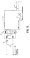
- Figure 5 schematically illustrates the hydraulic system used as a control apparatus and hydraulic fluid power.
- This device, the VoSmart valve is operated under positive hydraulic pressure and is hydraulically locked when not being operated. In the event of loss of hydraulic fluid in one of the hydraulic lines, the valve will remain locked in the last set position or fail safe position, in the event of loss of hydraulic fluid in both lines the valve will slowly close.
- the hydraulic fluid is propylene glycol or other fluid that is not an environmental hazard, in the event of loss of hydraulic fluid.
- the VoSmart valve is generally identified by the number 1 and is configured as a pipe section 10 having an upper end 20a and a lower end 20b.
- the apparatus incorporates fluid lines 9a and 9b which deliver hydraulic fluid under pressure to the double acting hydraulic actuator portion 5 of the valve which moves the throttling portion 6, which is configured as a sleeve over the "D" orifices 8 to control water flow through the orifices during the recharge operation.
- the line 9a is connected to chamber 5a to the left of the throttling portion 6 up while the line 9b is connected to the chamber 5b to push the throttling portion 6 down.
- the valve 1 When the pump is operating, the valve 1 is in the closed position 7.
- the VoSmart valve will have a flow inhibitor in the form of a check valve 36 at the location 3a indicated in Figure 1.
- the flow inhibitor is a blind flange installed at location 3.
- the recharge pipe 2 is connected to a source of pressurized water (connecting pipe 35 of Figure 5).
- a source of pressurized water connecting pipe 35 of Figure 5.
- the valve may be adjusted within the design range by observing a flow monitoring means or flow meter which is a part of the normal piping at the well head.
- the meter is also used to total and record the flow of water during pumping or recharge.
- the initial pumping rate and recharge rate is determined by a geologist at the time of drilling from pump tests and aquifer test data.
- the hydraulic power unit 27 ( Figure 6) is turned on and the switch operating the solenoid control valve 25 depressed in the close or open position, the hydraulic directional control valve 22 is shifted from the locked position by an electrical control 26 and hydraulic fluid is forced through the capillary lines 9, Figure 5, 1, by the pump 23, Figure 5, taking fluid from the reservoir 24 to one of the capillary tubes 9, Figure 5, 1, with hydraulic fluid returning in the other capillary tube 9 to the hydraulic storage tank 24, Figure 5, operate the valve 1 moving the throttling portion 6 to increase or decrease the size of the "D" ports 8.
- the speed of operation is set by adjusting the speed control valve 21, Figure 5.
- valve 1 Due to the wet environment that this valve operates in, the component parts of the valve 1, Figure 1, are fabricated from highly corrosive resistant steel.
- the column pipe 2 and the check valve or blind flange 3 are made of materials normally used for column pipes, check valves and blind flanges.
- Figure 7 shows the control system for removing entrained air from inside the drop pipe 2 of an Artificial Storage and Recovery (ASR) or recharge well.
- ASR Artificial Storage and Recovery
- SCADA Supervisory Control and Data Acquisition
- a SCADA control unit 36 monitoring pressure at the well head 32 so as to function as a control device to maintain a minimum pressure as well as a flow meter 34.
- the pressure sensor 30 may be located in a connecting pipe 35 to maintain a positive water pressure at the well head 32 of 5-10 PSI minimum.
- the water meter 34 is for monitoring and controlling the water flow rate through the system which is controlled by the valve 1.
- the pressure sensor 30 is monitored by a SCADA control unit 36 with appropriate electronic signals sent to a power unit 38 (which includes a motor and pump) for incremental adjustments to the power unit.
- the power unit 38 controls the hydraulic solenoid 25 and thus the valve 1 by pumping a hydraulic fluid in hoses 9a and 9b.
- the hydraulic power unit 38 preferably includes a pilot operated check valve 40. This feature hydraulically locks the hydraulic fluid in position when the directional solenoid valve 22 is in the center position or when the power unit 38 is shut off.
- the sequence of starting up the system is to have the valve 1 in the closed position.
- the drop pipe 2 is filled with water and the connecting piping 35 is pressurized. This allows the air inside the drop pipe 2 to escape through an air vacuum valve 40 at the well head 32.
- the valve 1 is then positioned manually or by the SCADA control unit 36 to reach and maintain a desired flow rate.
- the power unit 38 is normally powered down or placed in a stand-by mode by the SCADA control unit 36.
- the power unit 38 is turned on and adjustments are made to set or reset the water flow by monitoring the flow meter 34 with the SCADA control unit 36.
Landscapes
- Geology (AREA)
- Life Sciences & Earth Sciences (AREA)
- Engineering & Computer Science (AREA)
- Mining & Mineral Resources (AREA)
- Geochemistry & Mineralogy (AREA)
- Fluid Mechanics (AREA)
- Environmental & Geological Engineering (AREA)
- General Life Sciences & Earth Sciences (AREA)
- Physics & Mathematics (AREA)
- Sewage (AREA)
- Other Liquid Machine Or Engine Such As Wave Power Use (AREA)
- Control Of The Air-Fuel Ratio Of Carburetors (AREA)
- Magnetically Actuated Valves (AREA)
- Special Spraying Apparatus (AREA)
- Flow Control (AREA)
- Fluid-Driven Valves (AREA)
- Control Of Throttle Valves Provided In The Intake System Or In The Exhaust System (AREA)
- Pipeline Systems (AREA)
- Jet Pumps And Other Pumps (AREA)
Claims (8)
- Bohrlochströmungssteuerung (1) zur Verwendung in Kombination mit einem wiederbefüllbaren Bohrloch (13), um Wasser führende Schichten (17) wieder zu befüllen, wobei die Strömungssteuerung umfasst:gekennzeichnet durch:ein Ventil, das als ein Rohrabschnitt (20) konfiguriert ist, der ein oberes Ende (20a) zum Kopplen über das Wiederbefüllungsrohr (2) mit einer Quelle für mit Druck beaufschlagtes Wasser (12), einen Zwischenabschnitt (10) und ein unteres Ende zum Kopplen mit einer Strömungssperreinrichtung (3) aufweist;mehrere Auslassanschlüsse (8) in dem Zwischenabschnitt, durch die das mit Druck beaufschlagte Wasser in die Wasser führende Schicht strömt,eine Hülse (6) wenigstens über dem Zwischenabschnitt (10), wobei die Hülse (6) zwischen einer ersten Position (7), in der die Hülse die Auslassanschlüsse (8) abdeckt, um die Wasserströmung aus den Auslassanschlüssen (8) zu blockieren, und einer zweiten Position (7b), in der die Hülse (6) die Auslassanschlüsse (8) wenigstens teilweise freigibt, um die Wasserströmung daraus in die Wasser führende Schicht zu drosseln, beweglich ist, undeinen doppelt wirkenden Hydraulikaktuator (5), der der Hülse (6) zugeordnet ist, um die Hülse (6) zwischen der ersten Position (7a) und der zweiten Position (7b) zu bewegen, um das Wiederbefüllungsrohr (2) mit Wasser gefüllt zu halten, wodurch keine Luft in dem Wasser mitgerissen wird, wenn sich das Wasser durch das Wiederbefüllungsrohr (2) bewegt, wenn es in die Wasser führende Schicht eintritt; wobei der doppelt wirkende Aktuator (5) durch Hydraulikfluid in Hydraulikleitungen (9a, 9b) getrennt von dem Wiederbefüllungswasser angetrieben wird.
- Bohrlochströmungssteuerung (1) nach Anspruch 1, bei der der doppelt wirkende Hydraulikaktuator (5) ein Paar Hydraulikleitungen (9a, 9b) umfasst, die Druck in einer ersten Richtung anlegen, um die Hülse (6) so zu bewegen, dass sie die Auslassanschlüsse (8) abdeckt, und Druck in einer zweiten Richtung anlegen, um die Auslassanschlüsse (8) freizugeben.
- Bohrlochströmungssteuerung (1) nach Anspruch 2, bei der die Hydraulikleitungen (9a, 9b) mit einer oberirdischen Hydrauliksteuereinheit (26) verbunden sind, die eine Hydraulikpumpe (35) und ein Richtungssteuerventil (22) umfasst, wobei ein Durchflussmengensteuerventil (21) die Pumpe (35) mit den Leitungen (9a, 9b) verbindet, das Richtungssteuerventil (25) bestimmt, in welcher Richtung das Hydraulikfluid in den Hydraulikleitungen (9a, 9b) strömt, und somit bestimmt, ob die Hülse (6) die Auslassanschlüsse (8) abdeckt oder freigibt, und das Durchflussmengensteuerventil (21) die Geschwindigkeit steuert, mit der sich die Hülse (6) aus der ersten Position in die zweite Position bewegt.
- Bohrlochströmungssteuerung (1) nach Anspruch 2, die ferner ein Rückschlagventil (21) umfasst, das zwischen das Richtungssteuerventil (22) und die Hydraulikleitungen (9a, 9b) geschaltet ist, um das Hydraulikfluid unbeweglich zu halten, wenn sich das Richtungsventil (22) in einer Mittelposition befindet oder wenn die Pumpe (23) ausgeschaltet ist.
- Bohrlochströmungssteuerung (1) nach Anspruch 3, bei der die Querschnittsfläche der Auslassanschlüsse (8) in Richtung der zweiten Position abnimmt.
- Bohrlochströmungssteuerung (1) nach Anspruch 1, bei der das als ein Rohrabschnitt (20) konfigurierte Ventil eine mit dem oberen Ende gekoppelte Vertikalbohrlochpumpe (11) besitzt, wenn die Vertikalbohrlochpumpe (11) mit dem Wiederbefüllungsrohr (2) verbunden ist, das seinerseits mit einem Motorgenerator verbunden ist, wobei die Strömungssperreinrichtung (3) ein Rückschlagventil ist.
- Bohrlochströmungssteuerung (1) nach Anspruch 1, bei der das als ein Rohrabschnitt (20) konfigurierte Ventil an seinem oberen Ende direkt mit dem Wiederbefüllungsrohr (12) verbunden ist und an seinem unteren Ende mit einer Vertikalbohrlochpumpe (11) verbunden ist, wobei die Vertikalbohrlochpumpe (11) an ihrem anderen Ende ein Fußventil besitzt, wobei die Strömungssperreinrichtung ein Rückschlagventil (3a) ist.
- Bohrlochströmungssteuerung (1) nach Anspruch 1, bei der das als ein Rohrabschnitt (20) konfigurierte Ventil mit seinem oberen Ende mit dem Wiederbefüllungsrohr verbunden ist und die Strömungssperreinrichtung (3a) ein Blindflansch ist.
Applications Claiming Priority (3)
| Application Number | Priority Date | Filing Date | Title |
|---|---|---|---|
| US871652 | 1997-06-09 | ||
| US08/871,652 US5871200A (en) | 1997-06-09 | 1997-06-09 | Water well recharge throttle valve |
| PCT/US1998/011797 WO1998057083A1 (en) | 1997-06-09 | 1998-06-09 | Water well recharge throttle valve |
Publications (3)
| Publication Number | Publication Date |
|---|---|
| EP0988484A1 EP0988484A1 (de) | 2000-03-29 |
| EP0988484A4 EP0988484A4 (de) | 2002-05-15 |
| EP0988484B1 true EP0988484B1 (de) | 2005-08-24 |
Family
ID=25357856
Family Applications (1)
| Application Number | Title | Priority Date | Filing Date |
|---|---|---|---|
| EP98926407A Expired - Lifetime EP0988484B1 (de) | 1997-06-09 | 1998-06-09 | Drosselventil zum nachfüllen von wasserbrunnen |
Country Status (9)
| Country | Link |
|---|---|
| US (2) | US5871200A (de) |
| EP (1) | EP0988484B1 (de) |
| AT (1) | ATE302919T1 (de) |
| AU (1) | AU748767B2 (de) |
| CA (1) | CA2293391C (de) |
| DE (1) | DE69831328T2 (de) |
| DK (1) | DK0988484T3 (de) |
| ES (1) | ES2248905T3 (de) |
| WO (1) | WO1998057083A1 (de) |
Cited By (1)
| Publication number | Priority date | Publication date | Assignee | Title |
|---|---|---|---|---|
| NO20062806L (no) * | 2006-06-15 | 2007-12-17 | Nescos As | Fremgangsmåte og anordning for manøvrering av aktuatorer |
Families Citing this family (18)
| Publication number | Priority date | Publication date | Assignee | Title |
|---|---|---|---|---|
| NO306033B1 (no) * | 1998-06-05 | 1999-09-06 | Ziebel As | Anordning og fremgangsmate til innbyrdes uavhengig styring av reguleringsinnretninger for regulering av fluidstrom mellom et hydrokarbonreservoar og en bronn |
| US6247536B1 (en) | 1998-07-14 | 2001-06-19 | Camco International Inc. | Downhole multiplexer and related methods |
| US6811353B2 (en) | 2002-03-19 | 2004-11-02 | Kent R. Madison | Aquifer recharge valve and method |
| US7156578B2 (en) * | 2002-03-19 | 2007-01-02 | Madison Kent R | Aquifer recharge valve and method |
| US20060127184A1 (en) * | 2004-09-13 | 2006-06-15 | Madison Kent R | Aquifer recharge valve and method |
| US8092070B2 (en) | 2006-06-17 | 2012-01-10 | Maguire Stephen B | Gravimetric blender with power hopper cover |
| US10201915B2 (en) | 2006-06-17 | 2019-02-12 | Stephen B. Maguire | Gravimetric blender with power hopper cover |
| US7721799B2 (en) | 2006-10-06 | 2010-05-25 | Baski, Inc. | Flow control packer (FCP) and aquifer storage and recovery (ASR) system |
| US20100213396A1 (en) * | 2009-02-23 | 2010-08-26 | Peterson Mark H | Throttle Valve Used for Recharging Aquifers |
| CH702359A2 (fr) * | 2009-12-04 | 2011-06-15 | Cla Val Europ Sarl | Vanne tubulaire de régulation. |
| US8522887B1 (en) | 2010-05-18 | 2013-09-03 | Kent R. Madison | Aquifier flow controlling valve assembly and method |
| US8875790B2 (en) | 2011-05-11 | 2014-11-04 | Baski, Inc. | Method and system for fracking and completing wells |
| US9181795B2 (en) * | 2011-12-05 | 2015-11-10 | Jehangir Framroze PUNTHAKEY | Groundwater management system |
| US10138075B2 (en) | 2016-10-06 | 2018-11-27 | Stephen B. Maguire | Tower configuration gravimetric blender |
| CN104632155A (zh) * | 2015-02-08 | 2015-05-20 | 孔涛 | 水井注水防反吐器 |
| WO2017042724A1 (en) * | 2015-09-10 | 2017-03-16 | Rachapudi Vamsi Krishna | A system and a method for optimizing the usage of water and other resources in residential and commercial applications |
| US11536240B1 (en) | 2020-02-07 | 2022-12-27 | 3R Valve, LLC | Systems and methods of power generation with aquifer storage and recovery system |
| US12060768B2 (en) * | 2021-12-30 | 2024-08-13 | Halliburton Energy Services, Inc | Pressure-activated valve assemblies and methods to remotely activate a valve |
Family Cites Families (34)
| Publication number | Priority date | Publication date | Assignee | Title |
|---|---|---|---|---|
| US922060A (en) * | 1909-05-18 | Joseph J Stockdon | Valve. | |
| US353548A (en) * | 1886-11-30 | Half to solomon r | ||
| US1285769A (en) * | 1915-01-09 | 1918-11-26 | Charles W Mcconnel | Valve. |
| US1919955A (en) * | 1928-12-03 | 1933-07-25 | Leech William James Beaver | Gas offtake apparatus |
| US1799373A (en) * | 1929-04-02 | 1931-04-07 | J A Logan | Pumping mechanism |
| US2654395A (en) * | 1948-02-20 | 1953-10-06 | Kaye & Macdonald Inc | Valve for continuous boiler blowdown |
| CH282823A (de) * | 1950-06-06 | 1952-05-15 | Brankley Hollingbery William | Automatisches Abblasventil an dampfbetriebenen Maschinen. |
| US3120267A (en) * | 1960-12-05 | 1964-02-04 | Jersey Prod Res Co | Fluid flow control in wells |
| GB952007A (en) * | 1961-02-23 | 1964-03-11 | Kooperativa Foerbundet | Valve for quick shutting-off of a duct conveying fluid under pressure |
| US3220693A (en) * | 1961-05-31 | 1965-11-30 | Dickson Corp | Slurry throttle valve |
| US3497004A (en) * | 1967-05-25 | 1970-02-24 | Cook Testing Co | Tubing to tubing flow controlling retrievable sub-surface valve |
| US3761053A (en) * | 1969-10-01 | 1973-09-25 | Sno Trik Co | High pressure valve |
| BE754966A (fr) * | 1969-10-01 | 1971-02-18 | Sno Trik Co | Valves de haute pression |
| US4103696A (en) * | 1973-10-19 | 1978-08-01 | Cary Francis H | Control valve |
| US3937247A (en) * | 1974-01-23 | 1976-02-10 | Wal Jurjen V D | Valve for fluids containing abrasive particles |
| US3908536A (en) * | 1974-10-09 | 1975-09-30 | Chemetron Corp | Vacuumizing apparatus with internal flow control valve |
| US4047695A (en) * | 1975-03-28 | 1977-09-13 | Chappell Industries, Inc. | Adjustable choke |
| GB1534603A (en) * | 1975-09-02 | 1978-12-06 | Maezawa Kogyo | Sleeve valve |
| US4114851A (en) * | 1976-05-10 | 1978-09-19 | Sno-Trik Company | High pressure valve |
| US4134454A (en) * | 1977-09-21 | 1979-01-16 | Otis Engineering Corporation | Multi-stage sliding valve fluid operated and pressure balanced |
| US4377177A (en) * | 1979-04-16 | 1983-03-22 | Claycomb Jack R | Throttling mud choke apparatus |
| US4280569A (en) * | 1979-06-25 | 1981-07-28 | Standard Oil Company (Indiana) | Fluid flow restrictor valve for a drill hole coring tool |
| US4330012A (en) * | 1980-07-21 | 1982-05-18 | Chadwick Russell D | Valve for aerial spraying |
| US4540022A (en) * | 1982-06-01 | 1985-09-10 | Harry R. Cove | Choke for drilling or production use |
| US4508138A (en) * | 1983-08-05 | 1985-04-02 | Chas. M. Bailey Co., Inc. | Polyjet valve with backwash |
| US4569370A (en) * | 1983-11-14 | 1986-02-11 | Best Industries, Inc. | Balanced double cage choke valve |
| US4821622A (en) | 1986-12-22 | 1989-04-18 | Deere & Company | Extension and retraction sequencing circuit |
| US4691778A (en) * | 1987-02-09 | 1987-09-08 | Pyne R David G | Downhole water flow controller for aquifer storage recovery wells |
| US5172717A (en) * | 1989-12-27 | 1992-12-22 | Otis Engineering Corporation | Well control system |
| US5176164A (en) * | 1989-12-27 | 1993-01-05 | Otis Engineering Corporation | Flow control valve system |
| CA2031609C (en) * | 1990-12-05 | 1997-10-28 | Gregory Daniel William Pelech | Valve |
| US5101907A (en) * | 1991-02-20 | 1992-04-07 | Halliburton Company | Differential actuating system for downhole tools |
| US5503363A (en) * | 1994-05-06 | 1996-04-02 | Wallace; Glenn E. | Variable orifice valve |
| US5618022A (en) * | 1996-09-16 | 1997-04-08 | Wallace; Glenn E. | Variable orifice valve |
-
1997
- 1997-06-09 US US08/871,652 patent/US5871200A/en not_active Expired - Lifetime
-
1998
- 1998-06-09 AT AT98926407T patent/ATE302919T1/de not_active IP Right Cessation
- 1998-06-09 ES ES98926407T patent/ES2248905T3/es not_active Expired - Lifetime
- 1998-06-09 EP EP98926407A patent/EP0988484B1/de not_active Expired - Lifetime
- 1998-06-09 AU AU78252/98A patent/AU748767B2/en not_active Ceased
- 1998-06-09 WO PCT/US1998/011797 patent/WO1998057083A1/en not_active Ceased
- 1998-06-09 DK DK98926407T patent/DK0988484T3/da active
- 1998-06-09 DE DE1998631328 patent/DE69831328T2/de not_active Expired - Fee Related
- 1998-06-09 CA CA002293391A patent/CA2293391C/en not_active Expired - Fee Related
- 1998-06-09 US US09/445,606 patent/US6338466B1/en not_active Expired - Fee Related
Cited By (1)
| Publication number | Priority date | Publication date | Assignee | Title |
|---|---|---|---|---|
| NO20062806L (no) * | 2006-06-15 | 2007-12-17 | Nescos As | Fremgangsmåte og anordning for manøvrering av aktuatorer |
Also Published As
| Publication number | Publication date |
|---|---|
| DK0988484T3 (da) | 2006-01-09 |
| CA2293391C (en) | 2006-08-01 |
| WO1998057083A1 (en) | 1998-12-17 |
| AU748767B2 (en) | 2002-06-13 |
| US6338466B1 (en) | 2002-01-15 |
| AU7825298A (en) | 1998-12-30 |
| EP0988484A1 (de) | 2000-03-29 |
| ES2248905T3 (es) | 2006-03-16 |
| ATE302919T1 (de) | 2005-09-15 |
| CA2293391A1 (en) | 1998-12-17 |
| DE69831328D1 (de) | 2005-09-29 |
| EP0988484A4 (de) | 2002-05-15 |
| DE69831328T2 (de) | 2006-06-08 |
| US5871200A (en) | 1999-02-16 |
Similar Documents
| Publication | Publication Date | Title |
|---|---|---|
| EP0988484B1 (de) | Drosselventil zum nachfüllen von wasserbrunnen | |
| RU2523245C2 (ru) | Способы и системы обработки нефтяных и газовых скважин | |
| US5873410A (en) | Method and installation for pumping an oil-well effluent | |
| EP2636842B1 (de) | Ventilsystem | |
| US6073906A (en) | Water well recharge throttle valve | |
| US6491106B1 (en) | Method of controlling a subsurface safety valve | |
| EP2096254A2 (de) | Steuerungssystem für ein ringraumausgeglichenes Unteroberflächen-Sicherheitsventil | |
| US6368068B1 (en) | Multi-well computerized control of fluid pumping | |
| EP3055498A1 (de) | Übergangsventilsystem und verfahren zur gaserzeugung | |
| WO2010096349A2 (en) | Apparatus and system to actuate and pump well bore liquids from hydrocarbon wells | |
| US5128052A (en) | Wellbore liquid recovery apparatus and method | |
| US10233732B2 (en) | Active integrated flow control for completion system | |
| EP1127212B1 (de) | Hydraulische schaltervorrichtung | |
| US20100213396A1 (en) | Throttle Valve Used for Recharging Aquifers | |
| US3274940A (en) | Control system for well pump | |
| AU1006101A (en) | Electrohydraulic valve actuator | |
| RU2165517C2 (ru) | Способ фонтанной добычи нефти и устройство для его осуществления | |
| US20070107790A1 (en) | Control system for hydraulic cylinder, plug with a hydraulic cylinder and methods for setting and releasing a plug | |
| AU2022291528A1 (en) | A Valve and a Fluid System | |
| KR20240071577A (ko) | 자동제어 차수장치 | |
| US9725995B2 (en) | Bottle chamber gas lift systems, apparatuses, and methods thereof |
Legal Events
| Date | Code | Title | Description |
|---|---|---|---|
| PUAI | Public reference made under article 153(3) epc to a published international application that has entered the european phase |
Free format text: ORIGINAL CODE: 0009012 |
|
| 17P | Request for examination filed |
Effective date: 19991221 |
|
| AK | Designated contracting states |
Kind code of ref document: A1 Designated state(s): AT BE CH CY DE DK ES FI FR GB GR IE IT LI LU MC NL PT SE |
|
| A4 | Supplementary search report drawn up and despatched |
Effective date: 20020328 |
|
| AK | Designated contracting states |
Kind code of ref document: A4 Designated state(s): AT BE CH CY DE DK ES FI FR GB GR IE IT LI LU MC NL PT SE |
|
| 17Q | First examination report despatched |
Effective date: 20040311 |
|
| GRAP | Despatch of communication of intention to grant a patent |
Free format text: ORIGINAL CODE: EPIDOSNIGR1 |
|
| GRAS | Grant fee paid |
Free format text: ORIGINAL CODE: EPIDOSNIGR3 |
|
| GRAA | (expected) grant |
Free format text: ORIGINAL CODE: 0009210 |
|
| AK | Designated contracting states |
Kind code of ref document: B1 Designated state(s): AT BE CH CY DE DK ES FI FR GB GR IE IT LI LU MC NL PT SE |
|
| REG | Reference to a national code |
Ref country code: GB Ref legal event code: FG4D |
|
| REG | Reference to a national code |
Ref country code: CH Ref legal event code: EP |
|
| REG | Reference to a national code |
Ref country code: IE Ref legal event code: FG4D |
|
| REF | Corresponds to: |
Ref document number: 69831328 Country of ref document: DE Date of ref document: 20050929 Kind code of ref document: P |
|
| REG | Reference to a national code |
Ref country code: SE Ref legal event code: TRGR |
|
| REG | Reference to a national code |
Ref country code: CH Ref legal event code: NV Representative=s name: ISLER & PEDRAZZINI AG |
|
| REG | Reference to a national code |
Ref country code: GR Ref legal event code: EP Ref document number: 20050403557 Country of ref document: GR |
|
| REG | Reference to a national code |
Ref country code: DK Ref legal event code: T3 |
|
| REG | Reference to a national code |
Ref country code: ES Ref legal event code: FG2A Ref document number: 2248905 Country of ref document: ES Kind code of ref document: T3 |
|
| ET | Fr: translation filed | ||
| PLBE | No opposition filed within time limit |
Free format text: ORIGINAL CODE: 0009261 |
|
| STAA | Information on the status of an ep patent application or granted ep patent |
Free format text: STATUS: NO OPPOSITION FILED WITHIN TIME LIMIT |
|
| 26N | No opposition filed |
Effective date: 20060526 |
|
| REG | Reference to a national code |
Ref country code: CH Ref legal event code: PCAR Free format text: ISLER & PEDRAZZINI AG;POSTFACH 1772;8027 ZUERICH (CH) |
|
| PG25 | Lapsed in a contracting state [announced via postgrant information from national office to epo] |
Ref country code: CY Free format text: LAPSE BECAUSE OF NON-PAYMENT OF DUE FEES Effective date: 20060609 |
|
| PGFP | Annual fee paid to national office [announced via postgrant information from national office to epo] |
Ref country code: LU Payment date: 20080618 Year of fee payment: 11 Ref country code: DK Payment date: 20080612 Year of fee payment: 11 Ref country code: CH Payment date: 20080611 Year of fee payment: 11 |
|
| PGFP | Annual fee paid to national office [announced via postgrant information from national office to epo] |
Ref country code: AT Payment date: 20080612 Year of fee payment: 11 |
|
| PGFP | Annual fee paid to national office [announced via postgrant information from national office to epo] |
Ref country code: PT Payment date: 20080609 Year of fee payment: 11 Ref country code: MC Payment date: 20080613 Year of fee payment: 11 Ref country code: FI Payment date: 20080613 Year of fee payment: 11 Ref country code: IT Payment date: 20080626 Year of fee payment: 11 |
|
| PGFP | Annual fee paid to national office [announced via postgrant information from national office to epo] |
Ref country code: SE Payment date: 20080609 Year of fee payment: 11 Ref country code: NL Payment date: 20080603 Year of fee payment: 11 Ref country code: IE Payment date: 20080613 Year of fee payment: 11 Ref country code: ES Payment date: 20080717 Year of fee payment: 11 Ref country code: DE Payment date: 20080612 Year of fee payment: 11 |
|
| PGFP | Annual fee paid to national office [announced via postgrant information from national office to epo] |
Ref country code: FR Payment date: 20080617 Year of fee payment: 11 |
|
| PGFP | Annual fee paid to national office [announced via postgrant information from national office to epo] |
Ref country code: GB Payment date: 20080611 Year of fee payment: 11 |
|
| PGFP | Annual fee paid to national office [announced via postgrant information from national office to epo] |
Ref country code: BE Payment date: 20080813 Year of fee payment: 11 |
|
| PGFP | Annual fee paid to national office [announced via postgrant information from national office to epo] |
Ref country code: GR Payment date: 20080619 Year of fee payment: 11 |
|
| REG | Reference to a national code |
Ref country code: PT Ref legal event code: MM4A Free format text: LAPSE DUE TO NON-PAYMENT OF FEES Effective date: 20091209 |
|
| BERE | Be: lapsed |
Owner name: *VOV ENTERPRISES INC. Effective date: 20090630 |
|
| PG25 | Lapsed in a contracting state [announced via postgrant information from national office to epo] |
Ref country code: MC Free format text: LAPSE BECAUSE OF NON-PAYMENT OF DUE FEES Effective date: 20090630 Ref country code: FI Free format text: LAPSE BECAUSE OF NON-PAYMENT OF DUE FEES Effective date: 20090609 |
|
| REG | Reference to a national code |
Ref country code: CH Ref legal event code: PL |
|
| REG | Reference to a national code |
Ref country code: DK Ref legal event code: EBP |
|
| GBPC | Gb: european patent ceased through non-payment of renewal fee |
Effective date: 20090609 |
|
| NLV4 | Nl: lapsed or anulled due to non-payment of the annual fee |
Effective date: 20100101 |
|
| REG | Reference to a national code |
Ref country code: FR Ref legal event code: ST Effective date: 20100226 |
|
| PG25 | Lapsed in a contracting state [announced via postgrant information from national office to epo] |
Ref country code: PT Free format text: LAPSE BECAUSE OF NON-PAYMENT OF DUE FEES Effective date: 20091209 |
|
| REG | Reference to a national code |
Ref country code: IE Ref legal event code: MM4A |
|
| PG25 | Lapsed in a contracting state [announced via postgrant information from national office to epo] |
Ref country code: LI Free format text: LAPSE BECAUSE OF NON-PAYMENT OF DUE FEES Effective date: 20090630 Ref country code: IE Free format text: LAPSE BECAUSE OF NON-PAYMENT OF DUE FEES Effective date: 20090609 Ref country code: FR Free format text: LAPSE BECAUSE OF NON-PAYMENT OF DUE FEES Effective date: 20090630 Ref country code: CH Free format text: LAPSE BECAUSE OF NON-PAYMENT OF DUE FEES Effective date: 20090630 |
|
| PG25 | Lapsed in a contracting state [announced via postgrant information from national office to epo] |
Ref country code: GB Free format text: LAPSE BECAUSE OF NON-PAYMENT OF DUE FEES Effective date: 20090609 |
|
| PG25 | Lapsed in a contracting state [announced via postgrant information from national office to epo] |
Ref country code: DE Free format text: LAPSE BECAUSE OF NON-PAYMENT OF DUE FEES Effective date: 20100101 Ref country code: BE Free format text: LAPSE BECAUSE OF NON-PAYMENT OF DUE FEES Effective date: 20090630 Ref country code: AT Free format text: LAPSE BECAUSE OF NON-PAYMENT OF DUE FEES Effective date: 20090609 |
|
| PG25 | Lapsed in a contracting state [announced via postgrant information from national office to epo] |
Ref country code: NL Free format text: LAPSE BECAUSE OF NON-PAYMENT OF DUE FEES Effective date: 20100101 Ref country code: DK Free format text: LAPSE BECAUSE OF NON-PAYMENT OF DUE FEES Effective date: 20090630 |
|
| REG | Reference to a national code |
Ref country code: ES Ref legal event code: FD2A Effective date: 20090610 |
|
| PG25 | Lapsed in a contracting state [announced via postgrant information from national office to epo] |
Ref country code: GR Free format text: LAPSE BECAUSE OF NON-PAYMENT OF DUE FEES Effective date: 20100107 Ref country code: ES Free format text: LAPSE BECAUSE OF NON-PAYMENT OF DUE FEES Effective date: 20090610 |
|
| PG25 | Lapsed in a contracting state [announced via postgrant information from national office to epo] |
Ref country code: IT Free format text: LAPSE BECAUSE OF NON-PAYMENT OF DUE FEES Effective date: 20090609 |
|
| PG25 | Lapsed in a contracting state [announced via postgrant information from national office to epo] |
Ref country code: LU Free format text: LAPSE BECAUSE OF NON-PAYMENT OF DUE FEES Effective date: 20090609 |
|
| PG25 | Lapsed in a contracting state [announced via postgrant information from national office to epo] |
Ref country code: SE Free format text: LAPSE BECAUSE OF NON-PAYMENT OF DUE FEES Effective date: 20090610 |