EP2096254A2 - Steuerungssystem für ein ringraumausgeglichenes Unteroberflächen-Sicherheitsventil - Google Patents
Steuerungssystem für ein ringraumausgeglichenes Unteroberflächen-Sicherheitsventil Download PDFInfo
- Publication number
- EP2096254A2 EP2096254A2 EP09153547A EP09153547A EP2096254A2 EP 2096254 A2 EP2096254 A2 EP 2096254A2 EP 09153547 A EP09153547 A EP 09153547A EP 09153547 A EP09153547 A EP 09153547A EP 2096254 A2 EP2096254 A2 EP 2096254A2
- Authority
- EP
- European Patent Office
- Prior art keywords
- pressure
- valve
- safety valve
- chamber
- well
- Prior art date
- Legal status (The legal status is an assumption and is not a legal conclusion. Google has not performed a legal analysis and makes no representation as to the accuracy of the status listed.)
- Withdrawn
Links
- 230000004044 response Effects 0.000 claims abstract description 39
- 238000000034 method Methods 0.000 claims abstract description 23
- 239000012530 fluid Substances 0.000 claims description 35
- 238000004891 communication Methods 0.000 description 12
- 239000007789 gas Substances 0.000 description 11
- 230000003247 decreasing effect Effects 0.000 description 6
- 230000008901 benefit Effects 0.000 description 5
- 230000008878 coupling Effects 0.000 description 4
- 238000010168 coupling process Methods 0.000 description 4
- 238000005859 coupling reaction Methods 0.000 description 4
- 238000009434 installation Methods 0.000 description 3
- 241000191291 Abies alba Species 0.000 description 2
- IJGRMHOSHXDMSA-UHFFFAOYSA-N Atomic nitrogen Chemical compound N#N IJGRMHOSHXDMSA-UHFFFAOYSA-N 0.000 description 2
- 238000010276 construction Methods 0.000 description 2
- 238000006073 displacement reaction Methods 0.000 description 2
- 238000007792 addition Methods 0.000 description 1
- 230000004888 barrier function Effects 0.000 description 1
- 238000012217 deletion Methods 0.000 description 1
- 230000037430 deletion Effects 0.000 description 1
- 230000001419 dependent effect Effects 0.000 description 1
- 238000007667 floating Methods 0.000 description 1
- 230000002706 hydrostatic effect Effects 0.000 description 1
- 238000012423 maintenance Methods 0.000 description 1
- 238000004519 manufacturing process Methods 0.000 description 1
- 238000012986 modification Methods 0.000 description 1
- 230000004048 modification Effects 0.000 description 1
- 229910052757 nitrogen Inorganic materials 0.000 description 1
- 238000011017 operating method Methods 0.000 description 1
- 230000008439 repair process Effects 0.000 description 1
- 239000013535 sea water Substances 0.000 description 1
- 238000006467 substitution reaction Methods 0.000 description 1
- 238000012546 transfer Methods 0.000 description 1
Images


Classifications
-
- E—FIXED CONSTRUCTIONS
- E21—EARTH OR ROCK DRILLING; MINING
- E21B—EARTH OR ROCK DRILLING; OBTAINING OIL, GAS, WATER, SOLUBLE OR MELTABLE MATERIALS OR A SLURRY OF MINERALS FROM WELLS
- E21B34/00—Valve arrangements for boreholes or wells
- E21B34/06—Valve arrangements for boreholes or wells in wells
- E21B34/10—Valve arrangements for boreholes or wells in wells operated by control fluid supplied from outside the borehole
-
- F—MECHANICAL ENGINEERING; LIGHTING; HEATING; WEAPONS; BLASTING
- F16—ENGINEERING ELEMENTS AND UNITS; GENERAL MEASURES FOR PRODUCING AND MAINTAINING EFFECTIVE FUNCTIONING OF MACHINES OR INSTALLATIONS; THERMAL INSULATION IN GENERAL
- F16K—VALVES; TAPS; COCKS; ACTUATING-FLOATS; DEVICES FOR VENTING OR AERATING
- F16K31/00—Actuating devices; Operating means; Releasing devices
- F16K31/02—Actuating devices; Operating means; Releasing devices electric; magnetic
- F16K31/06—Actuating devices; Operating means; Releasing devices electric; magnetic using a magnet, e.g. diaphragm valves, cutting off by means of a liquid
- F16K31/08—Actuating devices; Operating means; Releasing devices electric; magnetic using a magnet, e.g. diaphragm valves, cutting off by means of a liquid using a permanent magnet
- F16K31/086—Actuating devices; Operating means; Releasing devices electric; magnetic using a magnet, e.g. diaphragm valves, cutting off by means of a liquid using a permanent magnet the magnet being movable and actuating a second magnet connected to the closing element
-
- F—MECHANICAL ENGINEERING; LIGHTING; HEATING; WEAPONS; BLASTING
- F16—ENGINEERING ELEMENTS AND UNITS; GENERAL MEASURES FOR PRODUCING AND MAINTAINING EFFECTIVE FUNCTIONING OF MACHINES OR INSTALLATIONS; THERMAL INSULATION IN GENERAL
- F16K—VALVES; TAPS; COCKS; ACTUATING-FLOATS; DEVICES FOR VENTING OR AERATING
- F16K31/00—Actuating devices; Operating means; Releasing devices
- F16K31/12—Actuating devices; Operating means; Releasing devices actuated by fluid
- F16K31/122—Actuating devices; Operating means; Releasing devices actuated by fluid the fluid acting on a piston
- F16K31/1221—Actuating devices; Operating means; Releasing devices actuated by fluid the fluid acting on a piston one side of the piston being spring-loaded
Definitions
- the present disclosure relates generally to equipment utilized and operations performed in conjunction with subterranean wells and, in an embodiment described herein, more particularly provides a control system for an annulus balanced subsurface safety valve.
- a typical subsurface safety valve can be annulus-balanced, that is, one side of a piston of an actuator in the safety valve is exposed to pressure in an annulus surrounding the safety valve.
- pressure is applied via a control line to an opposite side of the piston to displace the piston after overcoming a biasing force applied by a spring or other biasing device.
- a safety valve is operated utilizing well pressure in an annulus surrounding the safety valve.
- a valve controller alternately connects a piston chamber of the safety valve to well pressure or to a pressurized fluid source.
- a system for operating a safety valve in a subterranean well includes a piston of the safety valve which displaces in response to a pressure differential between chambers exposed to the piston.
- a valve controller alternately exposes at least one of the chambers to pressure in an annulus surrounding the safety valve, and to pressure greater than that in the annulus.
- a method of operating a safety valve in a subterranean well includes the steps of: opening the safety valve by biasing a piston of the safety valve to displace in response to a pressure differential between a chamber exposed to pressure greater than a pressure in the well, and another chamber exposed to the well pressure; and closing the safety valve by exposing both of the chambers to the well pressure.
- a system for operating a safety valve in a subterranean well includes a piston of the safety valve displaceable in response to a pressure differential between chambers exposed to the piston. At least one chamber is connected to a valve controller, and another chamber is connected to a well pressure. The valve controller is also connected to the well pressure, and to a pressurized fluid source which supplies pressure greater than that of the well pressure. The valve controller is operative to alternately connect the first chamber to the well pressure and to the pressurized fluid source, to thereby alternately open and close the safety valve.
- an aspect of the present invention provides a system for operating a safety valve in a subterranean well, the system comprising:
- the second chamber may be exposed to the pressure in the annulus.
- the safety valve closes in response to both of the first and second chambers being exposed to the pressure in the annulus.
- the safety valve opens in response to the first chamber being exposed to the pressure greater than that in the annulus, and the second chamber being exposed to the pressure in the annulus.
- the valve controller may include a control module responsive to pressure variation in the system, and the valve controller may further include a valve module operated by the control module and interconnected to the first chamber, the annulus and a source of the pressure greater than that in the annulus.
- valve controller is responsive to pressure in a line connected to the valve controller, whereby the valve controller connects the first chamber to the pressure greater than that in the annulus in response to a predetermined level of the pressure in the line. Also, the valve controller may connect the first chamber to pressure in the annulus in response to a predetermined decrease in the pressure in the line.
- a further aspect of the present invention provides a method of operating a safety valve in a subterranean well, the method comprising the steps of:
- the well pressure may be pressure in an annulus surrounding the safety valve.
- the opening step may further comprise operating a valve controller to connect the first chamber to the pressure greater than the well pressure, and the closing step may further comprise operating the valve controller to connect the first chamber to the well pressure.
- the method may further comprise the step of utilizing a control module of the valve controller to monitor the well pressure, the control module operating a valve module of the valve controller in response to a variation in the well pressure.
- the method may also further comprise the step of connecting the valve module to the first chamber, the well pressure, and the pressure greater than the well pressure.
- the method may further comprise the step of exposing the second chamber to the well pressure only after positioning the safety valve in the well.
- the method may further comprise the step of filling the second chamber with pressurized gas at a pressure greater than the well pressure prior to the step of positioning the safety valve in the well.
- Another aspect of the invention provides a system for operating a safety valve in a subterranean well, the system comprising:
- the well pressure may be pressure in an annulus surrounding the safety valve.
- the safety valve may open in response to the first chamber being exposed to the pressurized fluid source, and the safety valve may close in response to the first chamber being exposed to the well pressure.
- the valve controller may include a control module responsive to pressure variation in the well, and the valve controller may further include a valve module operated by the control module and interconnected to the first chamber, the well pressure and the pressurized fluid source.
- valve controller is responsive to pressure in a line connected to the valve controller, whereby the valve controller connects the first chamber to the pressurized fluid source in response to a predetermined level of pressure in the line.
- the valve controller may connect the first chamber to the well pressure in response to a predetermined decrease in the pressure in the line.
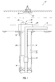
- FIG. 1 Representatively illustrated in FIG. 1 is a system 10 and associated method which embody principles of the present disclosure.
- a safety valve 12 is interconnected as part of a tubular string 14 and installed in a wellbore 16.
- An annulus 18 is thereby formed between the tubular string and the wellbore 16.
- the safety valve 12 is preferably of the type known as an annulus-balanced safety valve, in that an actuator for the safety valve includes a piston having one side exposed to pressure in the annulus 18. An opposite side of the piston is exposed to pressure in a line 20 extending to a remote location. Examples of such annulus-balanced safety valves are described more fully below.
- the safety valve 12 is also preferably of the type which fails closed, that is, when sufficient pressure is not present in the line 20, the valve closes due to force exerted by a biasing device (such as a spring or pressurized gas chamber, etc.).
- a biasing device such as a spring or pressurized gas chamber, etc.
- sufficient pressure must be applied to the line 20 to overcome the biasing force exerted by the biasing device, and to displace the piston and open a closure device of the valve.
- the pressure applied to the line 20 to open the safety valve is generally greater than pressure in the annulus 18 surrounding the safety valve.
- the system 10 does not have the line 20 connected directly to a pressure source 22 for pressurizing the line and opening the safety valve 12. Instead, the line 20 is connected to a valve controller 24 which, in the illustrated example, may be part of a subsea control module positioned at a subsea wellhead and Christmas tree 26.
- the pressure source 22 is depicted in FIG. 1 as being a pump located on a floating rig. However, other types of pressure sources (such as pressurized gas sources, etc.) may be used, and the pressure source may be located on land or on another type of rig, in keeping with the principles of this disclosure.
- the valve controller 24 preferably includes a valve module 28 and a control module 30.
- the control module 30 may not be used in some examples described below. Note that the valve and control modules 28, 30 are conveniently accessible for maintenance or repair on an exterior of the wellhead and Christmas tree 26. For example, conventional remotely operated submersible vehicles may be used to access and service the valve and control modules 28, 30.
- valve module 28 and/or control module 30 may be positioned internal to the tree 26, above the tree 26, in the annulus 18, attached to or incorporated into the safety valve 12, etc. Any position of the valve module 28 and control module 30 may be used in keeping with the principles of this disclosure.
- the valve module 28 includes one or more valves for selectively connecting the line 20 either to a line 32 extending to the pressure source 22, or to a line 34 extending to the annulus 18. In this manner, the line 20 may be placed in fluid communication with either the pressure source 22 or the annulus 18.
- the safety valve 12 can be opened in response to pressure greater than annulus pressure being applied from the pressure source to the line 20.
- pressure across the piston in the safety valve 12 is balanced, thereby allowing the biasing device in the safety valve to close the safety valve.
- the biasing device in the safety valve 12 does not have to raise a fluid column all the way from the safety valve to the surface when the safety valve is closed. This reduces the biasing force which must be exerted by the biasing device, thereby also reducing the pressure which must be applied to the line 32 when the safety valve 12 is opened.
- the safety valve 12 can be closed more rapidly, since the fluid in the line 20 does not have to be displaced all the way to the surface through the small line 32. Instead, the fluid in the line 20 can displace the relatively short distance to the valve module 28 and into the annulus 18 through the line 34.
- the safety valve 12 can be reliably closed, no matter what pressure exists in the annulus 18, since the valve module 28 ensures that the piston in the safety valve is balanced when the line 20 is placed in fluid communication with the line 34.
- prior annulus-balanced safety valve systems have been dependent upon pressure in the annulus being at a minimum level in order to displace the safety valve piston to a closed position. This minimum level of pressure in the annulus 18 may not exist if, for example, a packer 36 leaks, or the tubular string 14 above the packer leaks.
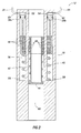
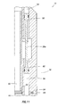
- FIG. 2 an example of the safety valve 12 which may be used in the system 10 is schematically illustrated.
- the safety valve 12 as depicted in FIG. 2 is similar in many respects to a safety valve described in U.S. Patent No. 6988556 , the entire disclosure of which is incorporated herein by this reference.
- the safety valve 12 includes pistons 38a,b, a biasing device 40, an opening prong 42, a closure member 44 and magnets 46 attached to the opening prong.
- the magnets 46 form a magnetic coupling with magnets 48 attached to the pistons 38a,b. In this manner, the magnetic coupling forces the opening prong 42 to displace with the pistons 38a, 38b.
- One advantage of the multiple separate pistons 38a,b is that one piston 38b (or set of pistons) may serve as a backup or spare, in case the other piston 38a (or set of pistons) becomes inoperable.
- a chamber 52 exposed to an upper side of the piston 38a is isolated from a chamber 54 exposed to an upper side of the piston 38b.
- annular chamber 56 which is in fluid communication with the annulus 18 surrounding the safety valve 12 via openings 58.
- the upper chamber 52 is in fluid communication with the line 20 via a port 60.
- the chamber 54 is in fluid communication with another line 64 via a port 62.
- the line 64 would preferably be connected to the valve controller 24 (or another similar valve controller, see FIGS. 9A & B and accompanying description of use of separate valve controllers) for use in case the safety valve 12 cannot be operated via pressure manipulation in the line 20.
- the valve controller 24 or another similar valve controller, see FIGS. 9A & B and accompanying description of use of separate valve controllers
- the valve 12 can be operated via pressure manipulation in the line 64.
- pressure in the line 20 is increased to a level sufficiently greater than pressure in the annulus 18 to thereby produce a pressure differential across the piston 38a, which overcomes the biasing force exerted by the biasing device 40, and displaces the flow tube 42 downward and opens the closure member 44 to permit fluid flow through an interior flow passage 66 of the tubular string 14.
- pressure in the line 20 is decreased to a level low enough to thereby reduce the pressure differential across the piston 38a, which allows the biasing device 40 to displace the opening prong 42 upward, so that the closure member 44 can pivot upward and close off the flow passage 66.
- the biasing device 40 could be a spring, pressurized gas chamber or other type of biasing device
- the closure member 44 could be a flapper, ball or other type of closure member
- the opening prong 42 could be another type of operating member
- the pistons 38a,b could be utilized simultaneously (i.e., by simultaneous pressure manipulations in the lines 20, 64) or separately, etc.
- valve module 28 includes an electrically operated solenoid valve or shuttle valve 68 which is interconnected to the lines 20, 32, 34.
- An electrical line 70 is connected to the control module 30.
- the valve 68 connects the line 20 to the line 34, thereby balancing pressures in the chambers 52, 56 of the safety valve 12, and allowing the biasing device 40 to close the safety valve.
- the valve 68 connects the line 20 to the line 32, thereby allowing increased pressure from the pressure source 22 to be transmitted to the chamber 52 to overcome the biasing force exerted by the biasing device 40 and open the safety valve 12.
- the control module 30 can be configured to monitor conditions in the well, and to electrically actuate the valve 68 via the line 70 when an unsafe condition is detected.
- the control module 30 may include one or more pressure sensors which are used to monitor pressure in the annulus 18 and/or pressure in the tubular string 14. If, for example, a sudden decrease in pressure in the tubular string 14 should occur (e.g., due to severing or other failure in a production pipeline 72), the safety valve 12 can be quickly closed by operating the valve 68 to connect the line 20 to the line 34.
- the valve 68 is in the configuration of FIG. 3A when an electrical signal is not supplied via the line 70, and the valve 68 is in the configuration of FIG. 3B when the electrical signal is supplied via the line 70.
- the safety valve 12 will close in the event of a failure of the control module 30 to supply the electrical signal.
- an electrical signal to shift the valve 68 could be supplied from another source, such as an alternate remote control module, etc.
- any source of an electrical signal may be used to shift the valve 68 in keeping with the principles of this disclosure.
- valve module 28 is schematically illustrated.
- the valve 68 is hydraulically (instead of electrically) operated.
- the valve 68 is of the type known as "self-piloted" in that it responds to pressure in one of the lines connected thereto (in this case, the line 32) in order to shift the valve from one configuration to another.
- pressure to shift the valve 68 could be supplied from another source, such as an alternate remote pressure source, a local pressure source, etc.
- any pressure source may be used to shift the valve 68 in keeping with the principles of this disclosure.
- the line 20 is connected by the valve 68 to line 34, thereby balancing pressure between the chambers 52, 56 and allowing the safety valve 12 to close.
- the valve 68 will be actuated to shift to another configuration in which the line 20 is connected to the line 32, thereby allowing the increased pressure to be communicated to the chamber 52 to open the safety valve 12.
- the valve 68 does not shift until there is sufficient pressure in the line 32 to open the safety valve 12 against the biasing force exerted by the biasing device 40 and any other force (such as friction forces, forces needed to displace the closure member 44, etc.) resisting displacement of the opening prong 42 to the open position.
- valve 68 will shift back to the configuration depicted in FIG. 4 , allowing the safety valve 12 to close.
- the safety valve 12 fails closed in the event of loss of pressure in the line 32.
- a vent or reference pressure 74 may be used to control how the predetermined level is referenced.
- the reference pressure 74 could be atmospheric pressure, in which case the predetermined level of pressure in the line 32 would be measured as gauge pressure above atmospheric pressure at the valve 68.
- the reference pressure 74 could be pressure in the annulus 18, in which case the predetermined level of pressure in the line 32 would be measured as pressure above that of the pressure in the annulus.
- the reference pressure 74 is sea pressure (i.e., hydrostatic pressure due to the sea water above the valve module 28).
- valve module 28 Any number or type of valves may be used in the valve module 28.
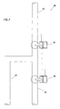
- a normally-elosed self-piloted hydraulically actuated valve 76 and a normally-open self-piloted hydraulically actuated valve 78 are schematically illustrated.
- valves 76, 78 may be interconnected to each other and the lines 20, 32, 34 in an example of the valve module 28 schematically depicted in FIG. 7 .
- valves 76, 78 may be interconnected to each other and the lines 20, 32, 34 in an example of the valve module 28 schematically depicted in FIG. 7 .
- other types of normally-open and/or normally-closed hydraulically or electrically operated valves may be used in place of the valves 76, 78, if desired.
- valve 76 is closed and valve 78 is open.
- valves 76, 78 are configured so that the valve 76 closes before the valve 78 opens.
- the line 20 is in communication with line 34, thereby balancing pressure in the chambers 52, 56 and allowing the safety valve 12 to close.
- pressure to shift the valves could be supplied from another source, such as an alternate remote pressure source, a local pressure source, etc.
- any pressure source may be used to shift the valves 76, 78 in keeping with the principles of this disclosure.
- valve 78 if pressure in the line 32 is increased to the predetermined level, the valve 78 will close and the valve 76 will open, thereby applying the increased pressure in the line 32 to the chamber 52 and opening the safety valve 12.
- the valve 76 does not open until there is sufficient pressure in the line 32 to open the safety valve 12 against the biasing force exerted by the biasing device 40 and any other force resisting displacement of the opening prong 42 to the open position.
- valve module 28 of FIG. 7 operates in response to pressure manipulation in the line 32 in much the same manner as the valve module of FIG. 4 .
- valve module 28 includes a rotary valve 80 which is hydraulically actuated and self-piloted.
- the line 20 is connected by the valve 80 to line 34, thereby balancing pressure between the chambers 52, 56 and allowing the safety valve 12 to close.
- the valve 80 will be actuated to rotate to another configuration (i.e., by displacing a piston 82 of an actuator 84 to the right as viewed in FIG. 8 ) in which the line 20 is connected to the line 32, thereby allowing the increased pressure to be communicated to the chamber 52 to open the safety valve 12.
- valve 80 will rotate back to the configuration depicted in FIG. 8 , allowing the safety valve 12 to close.
- the safety valve 12 fails closed in the event of loss of pressure in the line 32.
- pressure to actuate the valve 80 could be supplied from a source other than the line 32, such as an alternate remote pressure source, a local pressure source, etc.
- a source other than the line 32 such as an alternate remote pressure source, a local pressure source, etc.
- any pressure source may be used to shift the valve 80 in keeping with the principles of this disclosure.
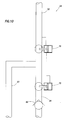
- FIGS. 9A & B Representatively illustrated in FIGS. 9A & B is a manner of switching between actuator pistons 38a,b in the safety valve 12, so that the safety valve may continue to be operated by one of the pistons even if it cannot be operated by the other piston.
- the valve module 28 in this example includes two sets of the normally-closed and normally-open valves 76a,b 78a,b.
- the valves 76a, 78a are used to control fluid communication between the line 20 and either the line 20 or the line 34, in the same manner as illustrated in FIG. 7 and described above.
- pressure in the line 20 can be decreased below the predetermined pressure, thereby providing communication between the lines 20, 34, balancing pressure across the piston 38a, and enabling fluid to be flowed between the lines 20, 34 as the piston 38a displaces upward and downward when the safety valve 12 is operated using the other piston 38b (which is displaced in response to pressure manipulation in the line 64).
- pressure in another line 86 (similar to the line 32 and connected to the pressure source 22 or another pressure source) is increased to the predetermined level in order to open the valve 76b and close the valve 78b.
- the valves 76b, 78b are configured so that the valve 78b closes before the valve 76b opens.
- the line 86 is thereby connected to the line 64 which is in communication with the chamber 54 in the safety valve 12, permitting a pressure differential across the piston 38b to displace the piston and open the safety valve.
- Pressure in the line 86 may be subsequently decreased below the predetermined level, thereby closing the valve 76b and opening the valve 78b, and permitting the biasing force exerted by the biasing device 40 to displace the piston 38b upward to close the safety valve 12.
- pressure manipulations in the line 86 may be used to operate the safety valve 12 in the same manner as pressure manipulations in the line 32 may be used to operate the safety valve, as described above.
- valve module 28 of FIG. 7 is schematically illustrated with a check valve 88 interconnected in the line 34.
- the check valve 88 allows fluid in the line 34 to be “flushed” each time the safety valve 12 is closed (due to fluid transfer from the line 20 to the line 34), while providing an additional barrier to release of pressure from the annulus 18 to the sea in subsea installations, or to the atmosphere in land installations.
- FIG. 11 another example of the safety valve 12 is schematically illustrated. Elements of the safety valve 12 of FIG. 11 which are somewhat similar to elements of the safety valve as illustrated in FIG. 2 are indicated in FIG. 11 using the same reference numbers.
- the safety valve 12 of FIG. 11 is similar in configuration to a type of safety valve known as a "dome charge" valve.
- the biasing device which biases the opening prong 42 upward to close the safety valve comprises a pressurized gas (such as Nitrogen) in the chamber 56. This pressurized gas biases the piston 38a to displace upward when pressure in the chamber 52 is less than pressure in the chamber 56.
- a pressurized gas such as Nitrogen
- the piston 38a in this configuration can be considered an assembly including an upper piston 90 and a lower piston 92.
- a lower side of the upper piston 90 is balanced relative to an upper side of the lower piston 92, in that both are exposed to pressure in the flow passage 66.
- the upper side of the piston 90 is exposed to pressure in the chamber 52, and the lower side of the piston 92 is exposed to pressure in the chamber 56, so the piston 38a assembly still responds to a pressure differential applied between the chambers 52, 56 as in the safety valve 12 of FIG. 2 .
- the opening 58 may be opened to permit fluid communication between the chamber 56 and the annulus 18 surrounding the safety valve 12.
- the safety valve 12 of FIG. 11 could be operated using the valve controller 24 and lines 20, 32, 34 as described above.
- the opening 58 may be opened using, for example, a valve or openable plug 94 which can be opened when the chamber 56 is no longer pressurized by the pressurized gas.
- a dome charge-type safety valve can be converted to an annulus-balanced safety valve in a well, without expending time and expense retrieving the safety valve from the well and converting it at the surface, or repairing or replacing the safety valve.
- the safety valve 12 can be originally installed as an annulus-balanceel safety valve with the opening 58 open (i.e., without use of the valve or openable plug 94).
- the safety valve 12 of FIG. 11 may be provided with a biasing device 40 (such as a spring) to upwardly bias the piston 38a and/or the opening prong 42, whether or not pressurized gas is used in the chamber 56.
- the piston 38a is connected directly to the opening prong 42 in the safety valve 12 of FIG. 11 , without use of the magnetic coupling of FIG. 2 described above.
- the safety valve 12 of FIG. 11 could be provided with a magnetic coupling to force the opening prong 42 to displace with the piston 38a, if desired.
- safety valve 12 Although only two configurations of the safety valve 12 have been described above, it should be clearly understood that any type of safety valve may be used in keeping with the principles of this disclosure.
- a tubing pressure-balanced safety valve could be used, in which case the line 34 and chamber 56 could be connected to the flow passage 66 of the tubular string 14, and the valve module 28 could alternately communicate the line 20 and chamber 52 to the line 32 or the line 34.
- the annulus 18 and the flow passage 66 of the tubular string 14 are examples of sources of well pressure which may be used in the system 10. Other sources of well pressure may be used in keeping with the principles of this disclosure.
- the system 10 and associated methods described above enable a safety valve to be conveniently and economically controlled without requiring excessively high pressure to be applied to the safety valve to overcome a large biasing force exerted by a biasing device of the safety valve.
- the system 10 also balances pressure across a piston of the safety valve quickly when it is desired to close the valve, no matter the level of pressure in the annulus or other well pressure source.
- the system 10 for operating a safety valve 12 in a subterranean well has been described above.
- the system 10 includes pistons 38a,b of the safety valve 12, with the pistons being responsive to displace due to a pressure differential between chambers 52, 54, 56 exposed to the pistons 38a,b.
- the system 10 further includes a valve controller 24 which alternately exposes the chamber 52 and/or 54 to pressure in an annulus 18 surrounding the safety valve 12, and to pressure greater than that in the annulus 18.
- the chamber 56 may be exposed to the pressure in the annulus 18.
- the safety valve 12 may close in response to each of the chambers 52, 54, 56 being exposed to the pressure in the annulus 18.
- the safety valve 12 may open in response to the chamber 52 and/or 54 being exposed to the pressure greater than that in the annulus 18, and the chamber 56 being exposed to the pressure in the annulus 18.
- the valve controller 24 may include a control module 30 responsive to pressure variation in the system 10.
- the valve controller 24 may further include a valve module 28 operated by the control module 30 and interconnected to the chamber 52 and/or 54, the annulus 18 and a source 22 of the pressure greater than that in the annulus 18.
- the valve controller 24 may be responsive to pressure in a line 32 connected to the valve controller, whereby the valve controller connects the chamber 52 and/or 54 to the pressure greater than that in the annulus 18 in response to a predetermined level of the pressure in the line.
- the valve controller 24 may connect the chamber 52 and/or 54 to pressure in the annulus 18 in response to a predetermined decrease in the pressure in the line 32.
- a method of operating a safety valve 12 in a subterranean well is also described above.
- the method may include the steps of: opening the safety valve 12 by biasing a piston 38a,b of the safety valve to displace in response to a pressure differential between a chamber 52 and/or 54 exposed to pressure greater than a well pressure, and a chamber 56 exposed to well pressure; and closing the safety valve 12 by exposing each of the chambers 52, 54, 56 to the well pressure.
- the well pressure may be pressure in an annulus 18 surrounding the safety valve 12.
- the opening step may also include operating a valve controller 24 to connect the chamber 52 and/or 54 to the pressure greater than the well pressure, and the closing step may also include operating the valve controller 24 to connect the chamber 52 and/or 54 to the well pressure.
- the method may include the step of utilizing a control module 30 of the valve controller 24 to monitor the well pressure.
- the control module 30 may operate a valve module 28 of the valve controller 24 in response to a variation in the well pressure.
- the method may include the step of connecting the valve module 28 to the chamber 52 and/or 54, the well pressure, and the pressure greater than the well pressure.
- the method may further include the step of exposing the chamber 56 to the well pressure only after positioning the safety valve 12 in the well.
- the method may also include the step of filling the chamber 56 with pressurized gas at a pressure greater than the well pressure prior to the step of positioning the safety valve 12 in the well.
- a system for operating a safety valve 12 in a subterranean well may comprise a piston 38a and/or 38b of the safety valve 12 displaceable in response to a pressure differential between chambers 52, 54, 56 exposed to the piston.
- the chamber 52 and/or 54 may be connected to a valve controller 24.
- the chamber 56 may be connected to a well pressure.
- the valve controller 24 may be connected to the well pressure and to a pressurized fluid source 22 which supplies pressure greater than that of the well pressure.
- the valve controller 24 may be operative to alternately connect the chamber 52 and/or 54 to the well pressure and to the pressurized fluid source 22, to thereby alternately open and close the safety valve 12.
- the well pressure may be pressure in an annulus 18 surrounding the safety valve 12.
- the safety valve 12 may open in response to the chamber 52 and/or 54 being exposed to the pressurized fluid source 22, and the safety valve may close in response to the chamber 52 and/or 54 being exposed to the well pressure.
- the valve controller 24 may include a control module 30 responsive to pressure variation in the well, and the valve controller may further include a valve module 28 operated by the control module and interconnected to the chamber 52 and/or 54, the well pressure and the pressurized fluid source 22.
- the valve controller 24 may be responsive to pressure in a line 32 connected to the valve controller, whereby the valve controller connects the chamber 52 and/or 54 to the pressurized fluid source 22 in response to a predetermined level of pressure in the line 32.
- the valve controller 24 may connect the chamber 52 and/or 54 to the well pressure in response to a predetermined decrease in the pressure in the line 32.
Landscapes
- Engineering & Computer Science (AREA)
- General Engineering & Computer Science (AREA)
- Mining & Mineral Resources (AREA)
- Geology (AREA)
- Life Sciences & Earth Sciences (AREA)
- Mechanical Engineering (AREA)
- Environmental & Geological Engineering (AREA)
- Fluid Mechanics (AREA)
- Physics & Mathematics (AREA)
- General Life Sciences & Earth Sciences (AREA)
- Geochemistry & Mineralogy (AREA)
- Fluid-Pressure Circuits (AREA)
- Safety Valves (AREA)
Applications Claiming Priority (1)
| Application Number | Priority Date | Filing Date | Title |
|---|---|---|---|
| US12/040,110 US8453749B2 (en) | 2008-02-29 | 2008-02-29 | Control system for an annulus balanced subsurface safety valve |
Publications (2)
| Publication Number | Publication Date |
|---|---|
| EP2096254A2 true EP2096254A2 (de) | 2009-09-02 |
| EP2096254A3 EP2096254A3 (de) | 2011-11-30 |
Family
ID=40756223
Family Applications (1)
| Application Number | Title | Priority Date | Filing Date |
|---|---|---|---|
| EP09153547A Withdrawn EP2096254A3 (de) | 2008-02-29 | 2009-02-24 | Steuerungssystem für ein ringraumausgeglichenes Unteroberflächen-Sicherheitsventil |
Country Status (2)
| Country | Link |
|---|---|
| US (1) | US8453749B2 (de) |
| EP (1) | EP2096254A3 (de) |
Cited By (1)
| Publication number | Priority date | Publication date | Assignee | Title |
|---|---|---|---|---|
| EP2881537A3 (de) * | 2013-12-05 | 2016-02-24 | GE Oil & Gas UK Limited | Hydraulisches Spülsystem |
Families Citing this family (19)
| Publication number | Priority date | Publication date | Assignee | Title |
|---|---|---|---|---|
| GB2484741B (en) * | 2010-10-22 | 2017-03-01 | Weatherford Tech Holdings Llc | Apparatus and methods for restricting flow in a bore |
| US9121250B2 (en) * | 2011-03-19 | 2015-09-01 | Halliburton Energy Services, Inc. | Remotely operated isolation valve |
| US20130180711A1 (en) * | 2012-01-13 | 2013-07-18 | Bp Corporation North America Inc. | Wellbore Pressure Actuation of Downhole Valves |
| US9388665B2 (en) * | 2012-06-12 | 2016-07-12 | Schlumberger Technology Corporation | Underbalance actuators and methods |
| US9631456B2 (en) * | 2013-12-31 | 2017-04-25 | Halliburton Energy Services, Inc. | Multiple piston assembly for safety valve |
| US10288185B2 (en) | 2016-09-30 | 2019-05-14 | Lawrence Osborne | Valve assembly |
| US10480284B2 (en) * | 2016-12-15 | 2019-11-19 | Silverwell Energy Ltd. | Balanced valve assembly |
| US10704363B2 (en) * | 2017-08-17 | 2020-07-07 | Baker Hughes, A Ge Company, Llc | Tubing or annulus pressure operated borehole barrier valve |
| BR112019025865B1 (pt) | 2017-08-23 | 2024-01-02 | Halliburton Energy Services, Inc | Sistema para acionar uma válvula de segurança de linha de equilíbrio, sistema e método |
| CN108150150B (zh) * | 2017-12-21 | 2024-04-16 | 中国电子科技集团公司第二十二研究所 | 测井仪 |
| WO2020023018A1 (en) * | 2018-07-24 | 2020-01-30 | Halliburton Energy Services, Inc. | Section-balanced electric safety valve |
| GB2588044B (en) * | 2018-07-26 | 2022-10-26 | Halliburton Energy Services Inc | Electric safety valve with well pressure activation |
| CN109667974A (zh) * | 2018-12-04 | 2019-04-23 | 贵州航天凯山石油仪器有限公司 | 一种高压差开启水量调节装置与方法 |
| CN109718955B (zh) * | 2019-03-08 | 2024-02-27 | 九牧厨卫股份有限公司 | 一种超薄自动除垢花洒 |
| US10954750B2 (en) | 2019-07-01 | 2021-03-23 | Saudi Arabian Oil Company | Subsurface safety valve with rotating disk |
| WO2022154944A1 (en) | 2021-01-14 | 2022-07-21 | Schlumberger Technology Corporation | Wellbore pressure insensitive hydraulic piston configuration |
| WO2023224617A1 (en) * | 2022-05-18 | 2023-11-23 | Halliburton Energy Services, Inc. | Subsurface safety valve with recoupling magnet assembly |
| US20250243944A1 (en) * | 2024-01-26 | 2025-07-31 | Fmc Technologies, Inc. | Magnetically actuated gate valve |
| US20250270895A1 (en) * | 2024-02-28 | 2025-08-28 | Halliburton Energy Services, Inc. | Safety valve employing a mechanical connecting apparatus having one or more magnetic targets |
Citations (1)
| Publication number | Priority date | Publication date | Assignee | Title |
|---|---|---|---|---|
| US6988556B2 (en) | 2002-02-19 | 2006-01-24 | Halliburton Energy Services, Inc. | Deep set safety valve |
Family Cites Families (18)
| Publication number | Priority date | Publication date | Assignee | Title |
|---|---|---|---|---|
| US4621695A (en) * | 1984-08-27 | 1986-11-11 | Camco, Incorporated | Balance line hydraulically operated well safety valve |
| US4667736A (en) * | 1985-05-24 | 1987-05-26 | Otis Engineering Corporation | Surface controlled subsurface safety valve |
| US5293551A (en) * | 1988-03-18 | 1994-03-08 | Otis Engineering Corporation | Monitor and control circuit for electric surface controlled subsurface valve system |
| US5101904A (en) * | 1991-03-15 | 1992-04-07 | Bruce Gilbert | Downhole tool actuator |
| US5251702A (en) * | 1991-07-16 | 1993-10-12 | Ava International Corporation | Surface controlled subsurface safety valve |
| US5526883A (en) * | 1994-10-13 | 1996-06-18 | Safoco, Inc. | Safety valve closure system |
| US5897095A (en) * | 1996-08-08 | 1999-04-27 | Baker Hughes Incorporated | Subsurface safety valve actuation pressure amplifier |
| US6237693B1 (en) * | 1999-08-13 | 2001-05-29 | Camco International Inc. | Failsafe safety valve and method |
| US6679332B2 (en) * | 2000-01-24 | 2004-01-20 | Shell Oil Company | Petroleum well having downhole sensors, communication and power |
| RU2260676C2 (ru) * | 2000-03-02 | 2005-09-20 | Шелл Интернэшнл Рисерч Маатсхаппий Б.В. | Система гидравлического привода, нефтяная скважина и способ управления скважинным устройством |
| US6619388B2 (en) * | 2001-02-15 | 2003-09-16 | Halliburton Energy Services, Inc. | Fail safe surface controlled subsurface safety valve for use in a well |
| FR2821611B1 (fr) | 2001-03-01 | 2003-07-04 | Sedis | Chaine de convoyage, notamment pour des transporteurs aeriens et en particulier dans des abattoirs |
| US6491106B1 (en) * | 2001-03-14 | 2002-12-10 | Halliburton Energy Services, Inc. | Method of controlling a subsurface safety valve |
| US6702025B2 (en) | 2002-02-11 | 2004-03-09 | Halliburton Energy Services, Inc. | Hydraulic control assembly for actuating a hydraulically controllable downhole device and method for use of same |
| US7350590B2 (en) * | 2002-11-05 | 2008-04-01 | Weatherford/Lamb, Inc. | Instrumentation for a downhole deployment valve |
| US7231971B2 (en) * | 2004-10-11 | 2007-06-19 | Schlumberger Technology Corporation | Downhole safety valve assembly having sensing capabilities |
| US20070272415A1 (en) * | 2006-05-24 | 2007-11-29 | Ratliff Lary G | Method and apparatus for equalizing pressure with a wellbore |
| US8038120B2 (en) | 2006-12-29 | 2011-10-18 | Halliburton Energy Services, Inc. | Magnetically coupled safety valve with satellite outer magnets |
-
2008
- 2008-02-29 US US12/040,110 patent/US8453749B2/en active Active
-
2009
- 2009-02-24 EP EP09153547A patent/EP2096254A3/de not_active Withdrawn
Patent Citations (1)
| Publication number | Priority date | Publication date | Assignee | Title |
|---|---|---|---|---|
| US6988556B2 (en) | 2002-02-19 | 2006-01-24 | Halliburton Energy Services, Inc. | Deep set safety valve |
Cited By (2)
| Publication number | Priority date | Publication date | Assignee | Title |
|---|---|---|---|---|
| EP2881537A3 (de) * | 2013-12-05 | 2016-02-24 | GE Oil & Gas UK Limited | Hydraulisches Spülsystem |
| US9981294B2 (en) | 2013-12-05 | 2018-05-29 | Ge Oil & Gas Uk Limited | Hydraulic flushing system |
Also Published As
| Publication number | Publication date |
|---|---|
| US8453749B2 (en) | 2013-06-04 |
| EP2096254A3 (de) | 2011-11-30 |
| US20090218096A1 (en) | 2009-09-03 |
Similar Documents
| Publication | Publication Date | Title |
|---|---|---|
| US8453749B2 (en) | Control system for an annulus balanced subsurface safety valve | |
| US7866402B2 (en) | Circulation control valve and associated method | |
| US8453746B2 (en) | Well tools with actuators utilizing swellable materials | |
| US6491106B1 (en) | Method of controlling a subsurface safety valve | |
| NO20074377L (no) | Sikkerhetsventil for setting dypt nede i en bronn | |
| US10808483B2 (en) | System for hydrocarbon recovery | |
| NO344219B1 (no) | Elektrisk kabeldrevet innsatt sikkerhetsventil | |
| NO329453B1 (no) | Trykkontrollanordning og fremgangsmate | |
| US10920529B2 (en) | Surface controlled wireline retrievable safety valve | |
| WO2010101775A2 (en) | Circulation control valve and associated method | |
| GB2342672A (en) | Pressure balanced piston control system for a subsurface safety valve | |
| GB2435655A (en) | Pressure protection for a control chamber of a well tool | |
| MX2011005797A (es) | Cabeza de pozo que cuenta con una valvula de seguridad integrada y metodo para fabricarla. | |
| NO342189B1 (no) | Hydraulisk aktuert styringssystem og fremgangsmåte for bruk i en undergrunnsbrønn | |
| CA2604654C (en) | Direct proportional surface control system for downhole choke | |
| US4223736A (en) | Method for shutting in a production well | |
| EP4692504A1 (de) | Betriebssicherheit für gasinjektion in unterirdischen bohrlöchern | |
| GB2378724A (en) | Retainer valve system for controlling fluid flow through a blowout preventer | |
| NO325229B1 (no) | Snorkelanordning for stromningsstyring |
Legal Events
| Date | Code | Title | Description |
|---|---|---|---|
| PUAI | Public reference made under article 153(3) epc to a published international application that has entered the european phase |
Free format text: ORIGINAL CODE: 0009012 |
|
| AK | Designated contracting states |
Kind code of ref document: A2 Designated state(s): AT BE BG CH CY CZ DE DK EE ES FI FR GB GR HR HU IE IS IT LI LT LU LV MC MK MT NL NO PL PT RO SE SI SK TR |
|
| AX | Request for extension of the european patent |
Extension state: AL BA RS |
|
| PUAL | Search report despatched |
Free format text: ORIGINAL CODE: 0009013 |
|
| AK | Designated contracting states |
Kind code of ref document: A3 Designated state(s): AT BE BG CH CY CZ DE DK EE ES FI FR GB GR HR HU IE IS IT LI LT LU LV MC MK MT NL NO PL PT RO SE SI SK TR |
|
| AX | Request for extension of the european patent |
Extension state: AL BA RS |
|
| RIC1 | Information provided on ipc code assigned before grant |
Ipc: E21B 34/10 20060101ALI20111026BHEP Ipc: E21B 23/04 20060101AFI20111026BHEP Ipc: F15B 21/00 20060101ALI20111026BHEP Ipc: F16K 31/06 20060101ALI20111026BHEP |
|
| AKY | No designation fees paid | ||
| REG | Reference to a national code |
Ref country code: DE Ref legal event code: R108 |
|
| RBV | Designated contracting states (corrected) |
Designated state(s): AT BE DE FR GB NO |
|
| REG | Reference to a national code |
Ref country code: DE Ref legal event code: R108 Effective date: 20120808 |
|
| 17P | Request for examination filed |
Effective date: 20120529 |
|
| RBV | Designated contracting states (corrected) |
Designated state(s): AT BE BG CH CY CZ DE DK EE ES FI FR GB GR HR HU IE IS IT LI LT LU LV MC MK MT NL NO PL PT RO SE SI SK TR |
|
| STAA | Information on the status of an ep patent application or granted ep patent |
Free format text: STATUS: EXAMINATION IS IN PROGRESS |
|
| 17Q | First examination report despatched |
Effective date: 20161222 |
|
| STAA | Information on the status of an ep patent application or granted ep patent |
Free format text: STATUS: THE APPLICATION HAS BEEN WITHDRAWN |
|
| 18W | Application withdrawn |
Effective date: 20170126 |