EP1127212B1 - Hydraulische schaltervorrichtung - Google Patents
Hydraulische schaltervorrichtung Download PDFInfo
- Publication number
- EP1127212B1 EP1127212B1 EP99948001A EP99948001A EP1127212B1 EP 1127212 B1 EP1127212 B1 EP 1127212B1 EP 99948001 A EP99948001 A EP 99948001A EP 99948001 A EP99948001 A EP 99948001A EP 1127212 B1 EP1127212 B1 EP 1127212B1
- Authority
- EP
- European Patent Office
- Prior art keywords
- rotor
- channel
- switch device
- holding cylinder
- track
- Prior art date
- Legal status (The legal status is an assumption and is not a legal conclusion. Google has not performed a legal analysis and makes no representation as to the accuracy of the status listed.)
- Expired - Lifetime
Links
- 239000012530 fluid Substances 0.000 claims description 38
- 238000004519 manufacturing process Methods 0.000 description 13
- XLYOFNOQVPJJNP-UHFFFAOYSA-N water Substances O XLYOFNOQVPJJNP-UHFFFAOYSA-N 0.000 description 12
- 238000004891 communication Methods 0.000 description 11
- 230000001276 controlling effect Effects 0.000 description 3
- 239000000203 mixture Substances 0.000 description 3
- 238000004140 cleaning Methods 0.000 description 2
- 230000004941 influx Effects 0.000 description 2
- 238000002347 injection Methods 0.000 description 2
- 239000007924 injection Substances 0.000 description 2
- 238000000034 method Methods 0.000 description 2
- 239000000126 substance Substances 0.000 description 2
- 238000012546 transfer Methods 0.000 description 2
- 238000013022 venting Methods 0.000 description 2
- 230000003213 activating effect Effects 0.000 description 1
- 230000015572 biosynthetic process Effects 0.000 description 1
- 230000000740 bleeding effect Effects 0.000 description 1
- 239000004020 conductor Substances 0.000 description 1
- 238000005516 engineering process Methods 0.000 description 1
- 238000011156 evaluation Methods 0.000 description 1
- 238000000605 extraction Methods 0.000 description 1
- 238000005755 formation reaction Methods 0.000 description 1
- 239000008241 heterogeneous mixture Substances 0.000 description 1
- 230000002401 inhibitory effect Effects 0.000 description 1
- 229910052500 inorganic mineral Inorganic materials 0.000 description 1
- 238000009434 installation Methods 0.000 description 1
- 238000012423 maintenance Methods 0.000 description 1
- 239000000463 material Substances 0.000 description 1
- 239000011707 mineral Substances 0.000 description 1
- 238000003825 pressing Methods 0.000 description 1
- 230000002035 prolonged effect Effects 0.000 description 1
- 230000001105 regulatory effect Effects 0.000 description 1
- 238000012360 testing method Methods 0.000 description 1
- 238000011144 upstream manufacturing Methods 0.000 description 1
- 238000012795 verification Methods 0.000 description 1
Images


Classifications
-
- E—FIXED CONSTRUCTIONS
- E21—EARTH OR ROCK DRILLING; MINING
- E21B—EARTH OR ROCK DRILLING; OBTAINING OIL, GAS, WATER, SOLUBLE OR MELTABLE MATERIALS OR A SLURRY OF MINERALS FROM WELLS
- E21B23/00—Apparatus for displacing, setting, locking, releasing or removing tools, packers or the like in boreholes or wells
- E21B23/004—Indexing systems for guiding relative movement between telescoping parts of downhole tools
- E21B23/006—"J-slot" systems, i.e. lug and slot indexing mechanisms
-
- E—FIXED CONSTRUCTIONS
- E21—EARTH OR ROCK DRILLING; MINING
- E21B—EARTH OR ROCK DRILLING; OBTAINING OIL, GAS, WATER, SOLUBLE OR MELTABLE MATERIALS OR A SLURRY OF MINERALS FROM WELLS
- E21B23/00—Apparatus for displacing, setting, locking, releasing or removing tools, packers or the like in boreholes or wells
- E21B23/04—Apparatus for displacing, setting, locking, releasing or removing tools, packers or the like in boreholes or wells operated by fluid means, e.g. actuated by explosion
- E21B23/0412—Apparatus for displacing, setting, locking, releasing or removing tools, packers or the like in boreholes or wells operated by fluid means, e.g. actuated by explosion characterised by pressure chambers, e.g. vacuum chambers
-
- E—FIXED CONSTRUCTIONS
- E21—EARTH OR ROCK DRILLING; MINING
- E21B—EARTH OR ROCK DRILLING; OBTAINING OIL, GAS, WATER, SOLUBLE OR MELTABLE MATERIALS OR A SLURRY OF MINERALS FROM WELLS
- E21B34/00—Valve arrangements for boreholes or wells
- E21B34/06—Valve arrangements for boreholes or wells in wells
- E21B34/10—Valve arrangements for boreholes or wells in wells operated by control fluid supplied from outside the borehole
Definitions
- the invention relates to a switch device which conducts one fluid stream to two or more independently operated hydraulic units.
- the invention will, for example, permit surface control with one hydraulic fluid stream of a number of downhole, series-connected, individually controllable admission valves, which are integrated in a production tubing which extends down into the sea bed for use, for example, in zone-isolated, perforated and/or open production areas in an oil/gas well.
- the different zones contain essentially different quantities of oil, gas and/or condensate, with the result that one or more zones successively produce increasing amounts of water as the zone is emptied.
- oil and water-containing consistency from several zones is produced until the average proportion of mixture is approximately 90% water.
- the bore hole has to be closed as no longer profitable according to a cost/benefit evaluation.
- the invention permits the total flow from the respective zones to be controlled by one hydraulic fluid stream from deck on the surface by activating one or more valves, which close one or more water-producing zones, with the added result that deposits of oil are forced into an adjacent advantageous zone.
- the zone or zones which produce undesirable amounts of water after prolonged production, and those zones which continue to produce acceptable oil concentrations are periodically registered.
- Downhole pressure is typically over/under 350 bar, with a temperature of over/under 100°C.
- Vertical installation depth is usually from 900 to 8000 metres, while the measured extent may be up to 6000 - 16000 metres.
- the principles can also be used for H 2 S and CO 2 environments where the question of material choice becomes crucial for translating the principles into practical implementation.
- a position meter or meters may also be inserted to indicate the degree of opening of the valve(s), thus giving the operator on the surface verification that the desired through-flow area has been achieved.
- an electro-hydraulic control system In order to obtain sequential co-operation of a number of, e.g., admission valves in the same well, an electro-hydraulic control system is currently employed, where an addressable solenoid valve only requires one fluid line from the control unit on the rig floor. The valves thus control the hydraulic power into respective valve chambers.
- a method for addressing one hydraulic fluid stream by means of a sequential fluid-switching device to two or more independent or series-connected operated units, e.g. hydraulic admission valves or fluid switches, permits surface control of downhole series-connected, individually steplessly adjustable units, which are integrated in a fluid-producing pipe lowered in zone-isolated perforated and/or open production areas in an oil/gas well, without the use of lowered cables for electronic control.
- independent or series-connected operated units e.g. hydraulic admission valves or fluid switches
- GB 2 213514 it is disclosed an apparatus for pressurized cleaning of flow conductors having a rotor which is movable relative to a cylinder by means of a zig-zag track and a lug of the above-mentioned type.
- the fluid which operates the rotor is the same fluid which flows in the string and which is used for the cleaning purpose. No further hydraulic devices are operated by the fluid.
- GB 2 248 465 it is disclosed a valve arrangement that enables the opening and closing of a test string circulation valve and tubing isolating valve. These valves are operated directly and mechanically by the rotor. The fluid which flows in and around the string is the same fluid with which the rotor and therefore the valves are operated.
- a purpose of the invention is to provide a switch device of the type mentioned in the introduction, with which a number of hydraulic devices may be operated independently of the well fluid which is transported in the bore hole and the string.
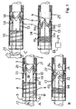
- Fig. 1A illustrates a hollow, cylindrical, e.g. four-fluid-switching device 1 having a rotor 21, which is mounted in a holding cylinder 20, which is placed in a production tubing or string 22.
- a rotor 21 With power supplied from one hydraulic line 2 to the rotor's 21 upper circular surface 3, the rotor 21 is pushed axially down towards a springing device 4 mounted between the rotor 21 and the holding cylinder's bottom seat or location 5.
- channels 8 and 8' spaced at 90° apart, which are open at a second end 8b, 8'b in towards the rotor's 1 outer diameter, and at the other or first end 8a, 8'a towards the bottom of the holding cylinder.
- the rotor's 21 wall there are provided four channels 11, 12, 13, 14 (or more) spaced at 90° apart; two of these, 11 and 12, are located spaced at 180° apart having a first end 11a and 12a respectively which communicates with the upper surface 3 of the rotor 21 and a second end 11b and 12b respectively which opens out in the rotor's 21 outer diameter immediately below the lower part of the rotor's guide track 7.
- fluid may flow from the top of the upper surface 3 of the rotor 21 through the rotor, i.e. from the first end 11, 12a of the channels 11, 12 respectively, down to the second end 11b, 12b of these channels.
- the other two of these channels 13 and 14 are located spaced at 180° apart and with the possibility for fluid to flow through from the spring housing's fluid volume 15 up to the device's outer diameter immediately below the device's guide track, i.e. from the first ends 8a, 8'a of the channels 8, 8', to the second ends 8b' 8'b of the channels.
- This now-established fluid communication is used, e.g., for controlling hydraulic tools connected to the output of channel 8 in the bottom of the cylinder's bottom location 5. Furthermore, there will now also be fluid communication between the channel 8' and the fluid volume in the spring housing 15 via the channel 14. This now-established fluid communication is used, e.g., for venting return fluid from hydraulic tools connected to the output 8'a of channel 8' in the bottom of the cylinder's bottom location 5.
- the next phase C is activated by relieving the hydraulic control pressure 2.
- the guide lugs 6 are thereby released from the parking location 9, and the now prestressed spring device 4 forces the rotor 21 up, while in the same way as in the first phase, the guide lugs 6 in engagement with the zigzag-shaped guide track 7 will force the rotor 21 to continue its helical travel in a new 45° to 90° in the same rotational direction.
- this phase there will now be the same communication situation as in phase A, but there is no fluid communication between the hydraulic line 2 and the channel 8. Nor is there any fluid communication between the channel 8' and the fluid volume in the spring housing 15.
- the third phase D is identical with the first, with the rotor 21 performing a new downwardly helical movement but with renewed rotation from 90° to 135°.
- the fourth phase (not shown) is identical with the starting position A, with the rotor 21 continuing the upwardly helical travel in a new 45° with rotation to 180°.
- a 180° rotation of the rotor 21 has therefore been implemented by means of pressure supply and pressure relief performed in succession.
- a similar, further operation may now be obtained by means of the channels 13 and 14 during a further rotation of the rotor 180° in similar steps of 45° to 360°.
- full rotation of the rotor 21 can be achieved by means of, e.g., three-part or six-part zigzag-shaped tracks, the deciding factor being the requirements and the practical constraints.
- Fig. 2 shows that switching of a fluid stream is implemented by permitting the hydraulic line's 2 power to pass a channel system 11, 12, 13 and 14 provided through the rotor 21, corresponding to one of the two fixed channel systems 8 and 8' in the cylinder 20, which systems pass the hydraulic power in sequence of rotation (I-IV) on to one of two different hydraulically operated units, such as admission valves or another fluid switch.
- Fig. 3 illustrates a developed single-plane drawing of a guide track's 7 angular waved shape; here illustrated with four 90° equally angled and identical waves calculated for four-part rotation of the rotor 21.
- a guide lug 6 is parked in each of the guide track's outer vertices 10, where a parking recess 9 ensures the guide lug's stability between each switch phase while fluid-switching operations are performed.
- the guide lug 6 slides axially and therefore unimpededly out of the parking location 9 and back into the guide track, whose vertices 10 always deviate from the axial centre line to such an extent that the guide lug 6 forces the rotor 21 into one and the same rotational direction.
- the guide track's 7 angular shape with vertices 10 therefore permits one-way rotating travel, and only a step-by-step travel. If, for example, a switch change is desired from phase two to phase four, switching must be performed via phase three. Not is it possible to switch back, for example, from phase three to phase two. In this case too switching must be performed from three to four to one to two.
- the method also permits, for example, six-phase full rotation, which is achieved with six equiangular waves, each at 60°, or with six different angular waves, such as 90° + 60° + 45° + 60° + 60° + 45°.
- the sequence of rotation (I - IV) is adapted to the rotors 21 channel throughputs 11, 12, 13 and 14 in order to co-ordinate hydraulic power to respective hydraulically operated units 24.
Landscapes
- Geology (AREA)
- Life Sciences & Earth Sciences (AREA)
- Engineering & Computer Science (AREA)
- Mining & Mineral Resources (AREA)
- Environmental & Geological Engineering (AREA)
- Fluid Mechanics (AREA)
- Physics & Mathematics (AREA)
- General Life Sciences & Earth Sciences (AREA)
- Geochemistry & Mineralogy (AREA)
- Fluid-Pressure Circuits (AREA)
- Earth Drilling (AREA)
- Supply Devices, Intensifiers, Converters, And Telemotors (AREA)
- Multiple-Way Valves (AREA)
Claims (4)
- Schalteinrichtung zum Betrieb einer Anzahl von hydraulischen Einheiten (24), die in einem Bohrloch (23) angeordnet sind, wobei
die Schalteinrichtung (1) angeordnet ist, um an einem Strang (22) befestigt zu werden, der in das Bohrloch (23) hinein eingeführt werden kann, und die Schalteinrichtung (1) und die hydraulisch betriebenen Einheiten (24) durch Zuführen eines Steuerdruckfluids an die Schalteinrichtung (1) betrieben werden können,
wobei die Schalteinrichtung (1) umfasst:dadurch gekennzeichnet, dass die Führung (7) in einer derartigen Weise gebildet ist, dass eine wiederholte alternierende Zuführung von Druckfluid an das erste longitudinale Ende des Rotors (21) und eine Entfernung des Druckfluids von dem ersten longitudinalen Ende des Rotors (21) eine Hin- und Herbewegung und eine einzelwegartige schrittweise Drehung des Rotors (21) relativ zu dem Haltezylinder (20) hervorruft, und dass in dem Rotor (21) angeordnet ist:einen Haltezylinder (20) mit einem ersten und zweiten longitudinalen Ende und der angeordnet ist, um in dem Strang (22) befestigt zu werden,einen Rotor (21) mit einem ersten und zweiten longitudinalen Ende und der drehbar in dem Haltezylinder (20) ist,ein Mittel (4) zum Vorspannen des Rotors (21) in Richtung auf das erste longitudinale Ende des Haltezylinders (20) hin, wobeidie Einrichtung derart angeordnet ist, dass ein Druckfluid unter Druck, das auf das erste Ende des Rotors angewendet wird, den Rotor veranlasst sich in Richtung auf das zweite longitudinale Ende des Haltezylinders (20) hin zu bewegen, wenn die Kraft, die von dem Druckfluid auf den Rotor (21) ausgeübt wird, die Kraft des Vorspannmittels (4) übersteigt,eine Anordnung einer Umfangsführung und eines zusammenwirkenden Ansatzes, die eine Führung (7) und wenigstens einen Ansatz (6) umfasst, zwischen dem Rotor (21) und dem Haltezylinder (20) vorgesehen ist, wobei der wenigstens eine Ansatz (6) in die Führung (7) hinein eingeführt ist, wobei die Führung (7) eine Anzahl von sukzessiven Führungsabschnitten (26, 27) umfasst, die in der Umfangsrichtung der Schalteinrichtung (1) und gleichzeitig in entgegengesetzte Weisen jeweils in Bezug auf die longitudinale Achse der Schalteinrichtung (1) verlaufen,wenigstens ein erster und ein zweiter Kanal (11 bzw. 12) mit einem ersten Ende (11a, 12a), der mit dem ersten longitudinalen Ende des Rotors (21) kommuniziert, und einem zweiten Ende (11b, 12b), welches sich in die äußere Seitenfläche des Rotors (21) auf einer ersten Ebene öffnet, die relativ zu dem Rotor (21) fest ist und transversal relativ zu der longitudinalen Achse des Rotors (21) verläuft,wenigstens einen dritten und einen vierten Kanal (13 bzw. 14) mit einem ersten Ende (13a, 14a), das mit dem zweiten longitudinalen Ende des Rotors (21) kommuniziert, und einem zweiten Ende (13b, 14b), welches sich in die äußere Seite der Rotoroberfläche auf der ersten Ebene hinein eröffnet, undin dem Haltezylinder (20) wenigstens ein fünfter Kanal (8) und ein sechster Kanal (8'), deren erste Enden (8a, 8a') ausgelegt sind, um mit jeweiligen Kanälen der hydraulisch betriebenen Einheiten (24) zu kommunizieren, und ein zweites Ende (8b, 8b'), welches sich in die innere Oberfläche des Haltezylinders (20) auf einer zweiten Ebene heraus öffnet, die transversal relativ zu der longitudinalen Achse des Haltezylinders (20) verläuft, angeordnet ist, wodurchdie Hin- und Her- und schrittweise Bewegung des Rotors (21) alternierend bewirkt, dass die Ebenen übereinstimmen, d.h. koplanar sind, oder nicht übereinstimmen, wodurch eine Verbindung des ersten oder des zweiten Kanals (11, 12) und des dritten oder des vierten Kanals (13, 14) mit dem fünften oder dem sechsten Kanal (8, 8') unterbrochen oder hergestellt werden kann. - Schalteinrichtung nach Anspruch 1, dadurch gekennzeichnet, dass der erste und der zweite Kanal (11, 12) in der gleichen Weise wie der dritte und der vierte Kanal (13, 14) zueinander im Winkel 180° versetzt sind, und dass der fünfte und sechste Kanal (8, 8') im Winkel 90° um die Achsen des Rotors (21) bzw. des Haltezylinders (20) herum versetzt sind.
- Schalteinrichtung nach Anspruch 1, dadurch gekennzeichnet, dass das Vorspannmittel eine Feder umfasst.
- Aufbau, umfassend eine Schalteinrichtung nach irgendeinem vorangehenden Anspruch, die in einem Strang (22) befestigt ist.
Priority Applications (1)
| Application Number | Priority Date | Filing Date | Title |
|---|---|---|---|
| DK99948001T DK1127212T3 (da) | 1998-10-05 | 1999-10-05 | Hydraulisk omskifteranordning |
Applications Claiming Priority (3)
| Application Number | Priority Date | Filing Date | Title |
|---|---|---|---|
| NO984646A NO309540B1 (no) | 1998-10-05 | 1998-10-05 | Pensinnretning som sekvensielt leder én hydraulisk fluidström til to eller flere uavhengig opererte hydrauliske enheter |
| NO984646 | 1998-10-05 | ||
| PCT/NO1999/000303 WO2000020721A1 (en) | 1998-10-05 | 1999-10-05 | Hydraulic switch device |
Publications (2)
| Publication Number | Publication Date |
|---|---|
| EP1127212A1 EP1127212A1 (de) | 2001-08-29 |
| EP1127212B1 true EP1127212B1 (de) | 2004-12-15 |
Family
ID=19902475
Family Applications (1)
| Application Number | Title | Priority Date | Filing Date |
|---|---|---|---|
| EP99948001A Expired - Lifetime EP1127212B1 (de) | 1998-10-05 | 1999-10-05 | Hydraulische schaltervorrichtung |
Country Status (10)
| Country | Link |
|---|---|
| US (1) | US6513589B1 (de) |
| EP (1) | EP1127212B1 (de) |
| AU (1) | AU755401B2 (de) |
| BR (1) | BR9915907A (de) |
| CA (1) | CA2346282C (de) |
| DK (1) | DK1127212T3 (de) |
| ID (1) | ID29015A (de) |
| NO (1) | NO309540B1 (de) |
| OA (1) | OA11789A (de) |
| WO (1) | WO2000020721A1 (de) |
Families Citing this family (9)
| Publication number | Priority date | Publication date | Assignee | Title |
|---|---|---|---|---|
| US7182139B2 (en) * | 2002-09-13 | 2007-02-27 | Schlumberger Technology Corporation | System and method for controlling downhole tools |
| US7337852B2 (en) * | 2005-05-19 | 2008-03-04 | Halliburton Energy Services, Inc. | Run-in and retrieval device for a downhole tool |
| US20080202766A1 (en) * | 2007-02-23 | 2008-08-28 | Matt Howell | Pressure Activated Locking Slot Assembly |
| US7730953B2 (en) | 2008-02-29 | 2010-06-08 | Baker Hughes Incorporated | Multi-cycle single line switch |
| NO20093421A1 (no) * | 2009-11-27 | 2011-05-30 | Tco As | Verktoy med utlosermekanisme |
| US8869886B2 (en) | 2011-07-28 | 2014-10-28 | Halliburton Energy Services, Inc. | Method to restrict the number of cycles in a continuous j-slot in a downhole tool |
| CA2927452C (en) | 2013-12-06 | 2018-01-09 | Halliburton Energy Services, Inc. | Hydraulic control of downhole tools |
| CN107339085B (zh) * | 2015-06-19 | 2019-09-24 | 泉州开云网络科技服务有限公司 | 一种全通径液压驱动分层注液及压裂装置的注液方法 |
| CN111287691B (zh) * | 2020-02-12 | 2020-10-30 | 四川百吉信石油科技有限公司 | 一种开关控制的油井控水工具 |
Family Cites Families (10)
| Publication number | Priority date | Publication date | Assignee | Title |
|---|---|---|---|---|
| US3814182A (en) * | 1973-03-13 | 1974-06-04 | Halliburton Co | Oil well testing apparatus |
| US3969937A (en) * | 1974-10-24 | 1976-07-20 | Halliburton Company | Method and apparatus for testing wells |
| US4260021A (en) * | 1979-01-09 | 1981-04-07 | Hydril Company | Plug catcher tool |
| US4321965A (en) | 1980-07-03 | 1982-03-30 | Otis Engineering Corporation | Self-aligning well tool guide |
| US4817723A (en) * | 1987-07-27 | 1989-04-04 | Halliburton Company | Apparatus for retaining axial mandrel movement relative to a cylindrical housing |
| US4781250A (en) * | 1987-12-14 | 1988-11-01 | Otis Engineering Corp. | Pressure actuated cleaning tool |
| US4848463A (en) * | 1988-11-09 | 1989-07-18 | Halliburton Company | Surface read-out tester valve and probe |
| GB9021488D0 (en) * | 1990-10-03 | 1990-11-14 | Exploration & Prod Serv | Drill test tools |
| US5103902A (en) * | 1991-02-07 | 1992-04-14 | Otis Engineering Corporation | Non-rotational versa-trieve packer |
| US5535767A (en) * | 1995-03-14 | 1996-07-16 | Halliburton Company | Remotely actuated adjustable choke valve and method for using same |
-
1998
- 1998-10-05 NO NO984646A patent/NO309540B1/no not_active IP Right Cessation
-
1999
- 1999-10-05 CA CA002346282A patent/CA2346282C/en not_active Expired - Fee Related
- 1999-10-05 BR BR9915907-4A patent/BR9915907A/pt not_active Application Discontinuation
- 1999-10-05 AU AU61268/99A patent/AU755401B2/en not_active Ceased
- 1999-10-05 ID IDW00200101025A patent/ID29015A/id unknown
- 1999-10-05 WO PCT/NO1999/000303 patent/WO2000020721A1/en not_active Ceased
- 1999-10-05 US US09/806,698 patent/US6513589B1/en not_active Expired - Lifetime
- 1999-10-05 DK DK99948001T patent/DK1127212T3/da active
- 1999-10-05 EP EP99948001A patent/EP1127212B1/de not_active Expired - Lifetime
- 1999-10-05 OA OA1200100083A patent/OA11789A/en unknown
Also Published As
| Publication number | Publication date |
|---|---|
| EP1127212A1 (de) | 2001-08-29 |
| NO309540B1 (no) | 2001-02-12 |
| AU755401B2 (en) | 2002-12-12 |
| WO2000020721A1 (en) | 2000-04-13 |
| DK1127212T3 (da) | 2005-02-14 |
| BR9915907A (pt) | 2001-08-21 |
| CA2346282C (en) | 2006-08-01 |
| AU6126899A (en) | 2000-04-26 |
| NO984646L (no) | 2000-04-06 |
| US6513589B1 (en) | 2003-02-04 |
| NO984646D0 (no) | 1998-10-05 |
| CA2346282A1 (en) | 2000-04-13 |
| OA11789A (en) | 2005-08-10 |
| ID29015A (id) | 2001-07-26 |
Similar Documents
| Publication | Publication Date | Title |
|---|---|---|
| DE60023131T2 (de) | Rückgewinnung von produktionsflüssigkeiten aus erdöl- bzw. erdgasbohrlöchern | |
| CA1301638C (en) | Pressure actuated cleaning tool | |
| RU2161698C2 (ru) | Способ одновременно-раздельной эксплуатации многопластовой скважины и приемный клапан для периодического перекрывания потока из пластов | |
| DK2636842T3 (en) | valve Plant | |
| Brown | Overview of artificial lift systems | |
| EP1127212B1 (de) | Hydraulische schaltervorrichtung | |
| NO322299B1 (no) | Anordning og fremgangsmate for styring av fluidstrom | |
| CA2293391C (en) | Water well recharge throttle valve | |
| US4681167A (en) | Apparatus and method for automatically and periodically introducing a fluid into a producing oil well | |
| US7703536B2 (en) | Gas assisted lift system | |
| NO329553B1 (no) | System og fremgangsmate for samtidig produksjon fra eller injeksjon inn i flere soner i en olje- eller gassbronn | |
| US7243721B2 (en) | Methods and apparatus for heating oil production reservoirs | |
| US8678095B2 (en) | Gas assisted lift system | |
| MXPA01003431A (en) | Hydraulic switch device | |
| US3685580A (en) | Dual zone completion system | |
| SU1213212A1 (ru) | Гидросистема секции механизированной крепи | |
| WO2011087715A2 (en) | Controllable chemical injection for multiple zone completions | |
| NO314203B1 (no) | Anordning for innströmningsregulering i et produksjonsrör for produksjon avolje eller gass fra et olje- og/eller gassreservoar | |
| DE19533046A1 (de) | Untertage-Tiefpumpenantrieb |
Legal Events
| Date | Code | Title | Description |
|---|---|---|---|
| PUAI | Public reference made under article 153(3) epc to a published international application that has entered the european phase |
Free format text: ORIGINAL CODE: 0009012 |
|
| 17P | Request for examination filed |
Effective date: 20010312 |
|
| AK | Designated contracting states |
Kind code of ref document: A1 Designated state(s): AT BE CH CY DE DK ES FI FR GB GR IE IT LI LU MC NL PT SE |
|
| AX | Request for extension of the european patent |
Free format text: AL;LT;LV;MK;RO;SI |
|
| RAP1 | Party data changed (applicant data changed or rights of an application transferred) |
Owner name: WEATHERFORD/LAMB, INC. |
|
| 17Q | First examination report despatched |
Effective date: 20021018 |
|
| REG | Reference to a national code |
Ref country code: DE Ref legal event code: 8566 |
|
| GRAP | Despatch of communication of intention to grant a patent |
Free format text: ORIGINAL CODE: EPIDOSNIGR1 |
|
| GRAS | Grant fee paid |
Free format text: ORIGINAL CODE: EPIDOSNIGR3 |
|
| GRAA | (expected) grant |
Free format text: ORIGINAL CODE: 0009210 |
|
| AK | Designated contracting states |
Kind code of ref document: B1 Designated state(s): DK FR GB IE IT NL |
|
| PG25 | Lapsed in a contracting state [announced via postgrant information from national office to epo] |
Ref country code: NL Free format text: LAPSE BECAUSE OF FAILURE TO SUBMIT A TRANSLATION OF THE DESCRIPTION OR TO PAY THE FEE WITHIN THE PRESCRIBED TIME-LIMIT Effective date: 20041215 Ref country code: IT Free format text: LAPSE BECAUSE OF FAILURE TO SUBMIT A TRANSLATION OF THE DESCRIPTION OR TO PAY THE FEE WITHIN THE PRESCRIBED TIME-LIMIT;WARNING: LAPSES OF ITALIAN PATENTS WITH EFFECTIVE DATE BEFORE 2007 MAY HAVE OCCURRED AT ANY TIME BEFORE 2007. THE CORRECT EFFECTIVE DATE MAY BE DIFFERENT FROM THE ONE RECORDED. Effective date: 20041215 Ref country code: FR Free format text: LAPSE BECAUSE OF FAILURE TO SUBMIT A TRANSLATION OF THE DESCRIPTION OR TO PAY THE FEE WITHIN THE PRESCRIBED TIME-LIMIT Effective date: 20041215 |
|
| REG | Reference to a national code |
Ref country code: GB Ref legal event code: FG4D |
|
| REG | Reference to a national code |
Ref country code: IE Ref legal event code: FG4D |
|
| REG | Reference to a national code |
Ref country code: DK Ref legal event code: T3 |
|
| NLV1 | Nl: lapsed or annulled due to failure to fulfill the requirements of art. 29p and 29m of the patents act | ||
| PG25 | Lapsed in a contracting state [announced via postgrant information from national office to epo] |
Ref country code: IE Free format text: LAPSE BECAUSE OF NON-PAYMENT OF DUE FEES Effective date: 20051005 |
|
| PLBE | No opposition filed within time limit |
Free format text: ORIGINAL CODE: 0009261 |
|
| STAA | Information on the status of an ep patent application or granted ep patent |
Free format text: STATUS: NO OPPOSITION FILED WITHIN TIME LIMIT |
|
| 26N | No opposition filed |
Effective date: 20050916 |
|
| EN | Fr: translation not filed | ||
| REG | Reference to a national code |
Ref country code: IE Ref legal event code: MM4A |
|
| REG | Reference to a national code |
Ref country code: DE Ref legal event code: 8566 |
|
| PGFP | Annual fee paid to national office [announced via postgrant information from national office to epo] |
Ref country code: GB Payment date: 20150930 Year of fee payment: 17 |
|
| REG | Reference to a national code |
Ref country code: GB Ref legal event code: 732E Free format text: REGISTERED BETWEEN 20151022 AND 20151028 |
|
| PGFP | Annual fee paid to national office [announced via postgrant information from national office to epo] |
Ref country code: DK Payment date: 20151012 Year of fee payment: 17 |
|
| REG | Reference to a national code |
Ref country code: DK Ref legal event code: EBP Effective date: 20161031 |
|
| GBPC | Gb: european patent ceased through non-payment of renewal fee |
Effective date: 20161005 |
|
| PG25 | Lapsed in a contracting state [announced via postgrant information from national office to epo] |
Ref country code: GB Free format text: LAPSE BECAUSE OF NON-PAYMENT OF DUE FEES Effective date: 20161005 |
|
| PG25 | Lapsed in a contracting state [announced via postgrant information from national office to epo] |
Ref country code: DK Free format text: LAPSE BECAUSE OF NON-PAYMENT OF DUE FEES Effective date: 20161031 |