EP0987539B1 - Système de mesure avec au moins une source d'excitation - Google Patents
Système de mesure avec au moins une source d'excitation Download PDFInfo
- Publication number
- EP0987539B1 EP0987539B1 EP99124388A EP99124388A EP0987539B1 EP 0987539 B1 EP0987539 B1 EP 0987539B1 EP 99124388 A EP99124388 A EP 99124388A EP 99124388 A EP99124388 A EP 99124388A EP 0987539 B1 EP0987539 B1 EP 0987539B1
- Authority
- EP
- European Patent Office
- Prior art keywords
- radiation
- sensor element
- excitation
- detector
- boundary face
- Prior art date
- Legal status (The legal status is an assumption and is not a legal conclusion. Google has not performed a legal analysis and makes no representation as to the accuracy of the status listed.)
- Expired - Lifetime
Links
Images

Classifications
-
- G—PHYSICS
- G01—MEASURING; TESTING
- G01N—INVESTIGATING OR ANALYSING MATERIALS BY DETERMINING THEIR CHEMICAL OR PHYSICAL PROPERTIES
- G01N21/00—Investigating or analysing materials by the use of optical means, i.e. using sub-millimetre waves, infrared, visible or ultraviolet light
- G01N21/62—Systems in which the material investigated is excited whereby it emits light or causes a change in wavelength of the incident light
- G01N21/63—Systems in which the material investigated is excited whereby it emits light or causes a change in wavelength of the incident light optically excited
- G01N21/64—Fluorescence; Phosphorescence
- G01N21/6408—Fluorescence; Phosphorescence with measurement of decay time, time resolved fluorescence
-
- G—PHYSICS
- G01—MEASURING; TESTING
- G01N—INVESTIGATING OR ANALYSING MATERIALS BY DETERMINING THEIR CHEMICAL OR PHYSICAL PROPERTIES
- G01N21/00—Investigating or analysing materials by the use of optical means, i.e. using sub-millimetre waves, infrared, visible or ultraviolet light
- G01N21/62—Systems in which the material investigated is excited whereby it emits light or causes a change in wavelength of the incident light
- G01N21/63—Systems in which the material investigated is excited whereby it emits light or causes a change in wavelength of the incident light optically excited
- G01N21/64—Fluorescence; Phosphorescence
- G01N21/6428—Measuring fluorescence of fluorescent products of reactions or of fluorochrome labelled reactive substances, e.g. measuring quenching effects, using measuring "optrodes"
-
- G—PHYSICS
- G01—MEASURING; TESTING
- G01N—INVESTIGATING OR ANALYSING MATERIALS BY DETERMINING THEIR CHEMICAL OR PHYSICAL PROPERTIES
- G01N21/00—Investigating or analysing materials by the use of optical means, i.e. using sub-millimetre waves, infrared, visible or ultraviolet light
- G01N21/62—Systems in which the material investigated is excited whereby it emits light or causes a change in wavelength of the incident light
- G01N21/63—Systems in which the material investigated is excited whereby it emits light or causes a change in wavelength of the incident light optically excited
- G01N21/64—Fluorescence; Phosphorescence
- G01N21/645—Specially adapted constructive features of fluorimeters
- G01N21/648—Specially adapted constructive features of fluorimeters using evanescent coupling or surface plasmon coupling for the excitation of fluorescence
-
- G—PHYSICS
- G01—MEASURING; TESTING
- G01N—INVESTIGATING OR ANALYSING MATERIALS BY DETERMINING THEIR CHEMICAL OR PHYSICAL PROPERTIES
- G01N21/00—Investigating or analysing materials by the use of optical means, i.e. using sub-millimetre waves, infrared, visible or ultraviolet light
- G01N21/01—Arrangements or apparatus for facilitating the optical investigation
- G01N21/03—Cuvette constructions
- G01N2021/0346—Capillary cells; Microcells
-
- G—PHYSICS
- G01—MEASURING; TESTING
- G01N—INVESTIGATING OR ANALYSING MATERIALS BY DETERMINING THEIR CHEMICAL OR PHYSICAL PROPERTIES
- G01N21/00—Investigating or analysing materials by the use of optical means, i.e. using sub-millimetre waves, infrared, visible or ultraviolet light
- G01N21/01—Arrangements or apparatus for facilitating the optical investigation
- G01N21/03—Cuvette constructions
- G01N21/05—Flow-through cuvettes
Definitions
- the invention relates to a measuring arrangement with at least one radiation source Provision of an excitation radiation, with a first luminescence optical Sensor element, with at least one detector, an evaluation unit for the detection of a Measuring radiation and a transparent for the excitation and the measuring radiation Carrier element, which has a first interface for attaching the luminescence optical Sensor element, a second interface for receiving the excitation radiation and a third interface for emitting the measuring radiation of the sensor element to the detector
- the direction of the excitation radiation is one with the detection direction Angles between 60 ° and 120 °, preferably an angle of essentially 90 °, includes and the refractive index of the carrier element is greater than that of the environment.
- a measuring arrangement of the type mentioned at the outset is, for example, from AT-B 383 684 known.
- a transparent support element of this measuring arrangement with plane-parallel Boundary surfaces have a sensor layer on one of these surfaces, this sensor layer is excited by a radiation source with excitation radiation.
- the light the radiation source falls through a diaphragm device onto the sensor layer, the resulting measuring radiation is essentially normal to the direction of the excitation radiation a detector arranged on a lateral boundary surface of the carrier element becomes.
- the light is guided in the carrier element essentially by total reflection the measuring radiation at the boundary surfaces of the carrier element.
- a sensor chamber is arranged with the sensor layer, which via a Has inlet and an outlet for the sample and flushed through by the sample to be measured can be.
- the sample or the analyte to be measured in the sample changes an optical one Property of the luminescence indicator in the sensor layer, which differs from that of the detector detected measurement radiation changes depending on the analyte concentration.
- EP-B1 0 354 895 describes a disposable measuring element for the simultaneous measurement of several different sample components known, which consists of a sensor part and thus connected sampling part exists.
- the sensor part has a sample channel in which several sensors are arranged.
- the excitation of the sensors or the detection of the Measuring radiation takes place via light guides to each of the sensors, with the evaluation the light signals in an excitation and measuring device, not shown he follows.
- a sample chamber with transparent, opposite walls is on the Provided on the inside with a luminescence indicator, which is arranged in an indicator layer is.
- the excitation radiation emitted by several light sources passes through one transparent wall of the measuring chamber on the sample, for example a gas to be measured, which interacts with the indicator layer.
- a sensor element for the simultaneous determination of the concentration of several substances in a sample is also described in US-A 5,039,490.
- Sensor elements are arranged side by side photosensitive elements and light-emitting sources, which are covered by a transparent coupling layer.
- the indicator layer On this coupling layer there is the indicator layer, which in turn has a the cover layer in contact with the sample can be covered. That is relatively complicated built-up sensor element requires filters or optical gratings to backscatter the excitation light to avoid in the photosensitive elements.
- Indicator substances for individual photosensitive elements can be used simultaneously several different sample components are measured.
- the measuring chamber is designed as a flow measuring cell. This essentially consists of two injection molded parts made of a plastic material which is transparent for the excitation and measuring radiation of the luminescence optical sensors used. Connections for the sample inflow or outflow are formed on the front ends of the measuring cell.
- the base part of the measuring chamber has three cylindrical recesses for receiving the sensor elements in a sensor area.
- the cover part of the measuring chamber there is a groove-shaped depression which, together with the base part, forms the measuring channel, which has a sample volume of approximately 40 ⁇ l.
- the excitation of the luminescence indicator in the individual luminescence-optical sensor elements, as well as the detection of the luminescence radiation takes place via light guides which are directed onto the base part of the measuring chamber.
- the object of the present invention is based on the prior art mentioned To propose measuring arrangement, which is simple and inexpensive to manufacture, without use of filters and optical gratings in the carrier element several different at the same time Sample components can be measured. Another requirement exists in forming the support element of the measuring arrangement as a disposable element.
- This object is achieved in that according to a first embodiment on the first interface at least one other, preferably different from the first, luminescence optical connected by a common sample channel Sensor element is arranged that each sensor element and a separate radiation source a common detector is assigned to all sensor elements, and that an electronic one Control devices are provided with which the separate radiation sources form a temporally offset delivery of the excitation radiation are connected (multiplex method), so that the separation of the light paths of the measuring radiation of each sensor element by staggered in time Success of the sensor elements.
- the excitation radiation is therefore advantageous not only for the excitation radiation to be different optical ones
- Light paths from the measuring radiation but also from the individual sensor elements each emitted measuring radiation by electronic described in more detail below and / or separated mathematical device or method.
- This measure can optical filters or optical lattice structures in the carrier element can be dispensed with.
- each sensor element a separate radiation source and all sensor elements a common detector be assigned.
- An embodiment variant is characterized in that an electronic device for periodic modulation of the excitation radiation, which with the separate radiation sources is connected, a device for periodically modulated measurement radiation measurement, which is connected to the detector and a device for measuring the phase angle and / or the demodulation between excitation and measurement radiation is provided.
- the Cooldown or its change can thus also from demodulation, ie. H. the reduction the amplitude of the measuring radiation compared to the excitation radiation.
- a pulsed excitation with subsequent decay time measurement can be advantageous in those cases are used where a separate radiation source is assigned to each sensor element is.
- Such a variant is characterized in that a device for pulsed excitation of the sensor elements, which are connected to the separate radiation sources is, and a device for time-resolved detection of the measuring radiation, which with is connected to the detector is provided.
- all sensor elements with a common, pulsed radiation source and a common detector in are optical connection, the detector for separating the light paths of the measuring radiation each sensor element with a device for the temporally offset detection of Measuring radiation is connected.
- the separation of the light paths can also be followed by a Unit for the mathematical separation of the cooldown functions of the individual Sensor elements are made.
- several sensor elements can be used a radiation source and a common detector can be used.
- this detector also the decay time profiles of all Detect sensor elements simultaneously, the evaluation device then being a unit for has mathematical separation of the decay time functions of the individual sensor elements.
- the number of sensor elements is limited and depends on the extent to which the average time constant of the decay times of the individual sensor elements are different. Good measurement results can be achieved if distinguish the mean time constants of the decay times by at least a factor of two.
- the carrier element can be used for light conduction between the sensor elements and the Detector or the detectors by means of total reflection.
- the carrier element can be used for light conduction between the sensor elements and the Detector or the detectors by means of total reflection.
- the excitation radiation between Light source and the sensor elements is guided by means of total reflection in the carrier element.
- the support element can be in all design variants including sensor elements and Sample channel can be designed as an inexpensive disposable element, the interfaces of which the insertion in a measuring device as contact surfaces for those arranged in the measuring device Radiation sources or detectors are used.
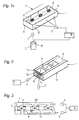
- All of the embodiment variants of the measuring arrangement according to the invention shown in FIGS. 1 to 3 have a transparent carrier element for the excitation and measuring radiation used 1, with an interface 11 the luminescence-optical sensor elements 2, 2 ' records, the excitation radiation radiated through the interface 12 and through the Interface 13 the measuring radiation is emitted.
- the interface 12 is therefore the one or more Light sources 3 and the interface 13 assigned to the detector (s) 4, 4 '.
- the direction of the excitation radiation is essentially normal to the direction of detection, but also angles from 60 to 120 ° are permissible.
- All sensor elements 2, which are preferably different Indicator materials for measuring different parameters are marked by a common sample channel 6 connected.
- the capillary sample channel 6 and its housing structure 7 are only indicated schematically.
- the sample channel can be a square, rectangular or have a substantially semicircular cross-section, with extensions in the area of the individual sensor elements 2, 2 'are permissible.
- Carrier element 1 which can be cuboidal, for example.
- the individual sensor elements 2 are arranged, respectively through the interfaces 12 and 13, respectively, the excitation radiation or the measurement radiation is detected.
- a second similar component or housing 7, in which the sample channel 6, for example, is embedded in a groove shape, can with the carrier element 1 z. B. glued or connected by other suitable means.
- FIG. 1a has separate radiation sources 3 for each of the sensor elements 2 and a detector 4 assigned on the end side, here the excitation via a device 16 takes place at different times according to the so-called multiplex method.
- Simultaneous measurement in connection with the present invention thus means Measurement of several parameters as part of a sample loading of the sample channel.
- Fig. 1b are the individual radiation sources of a side surface 12 of the carrier element assigned, the excitation of the individual sensor elements either by the evanescent Share of the excitation wave or by suitable adjustment of the refractive index in the Range of sensor spots can be done.
- the excitation radiation periodically modulated via the device 17, wherein a periodically modulated detection of the measuring radiation takes place.
- the facilities 17 and 18 are connected to a signal line 23, so that the measurement of the phase angle in the evaluation unit and / or the demodulation between excitation and measurement radiation can take place.
- FIG. 1c shows an embodiment variant in which all sensor elements 2 have a common, pulsed radiation source 3 and a common detector 4 is assigned. After the common, pulsed excitation of all sensor elements 2, the detection takes place through temporally offset measuring points or measuring windows. With this variant, however, the mean time constant of the decay time of the individual sensor elements differs significantly his.
- the detector 4 can be provided with a device 19 for the mathematical separation of the decay time functions of the individual sensor elements.
- FIG. 2 A variant of the embodiments according to FIGS. 1a to 1c is shown in FIG. 2.
- the carrier element 1 has delimited regions 15 in the area of the sensor elements 2, whose refractive index n 2 is greater than the refractive index n 1 of the actual carrier element.
- the excitation radiation can be supplied directly and / or by means of total reflection via the regions 15 with the larger refractive index n 2 .
- the fluorescence radiation emitted in all spatial directions reaches, among other things, the lateral areas of the carrier element 1 and is there derived directly and / or by means of total reflection to one of the two end faces 13 and detected by the detector 4.
- FIG. 3 A very compact variant is shown in FIG. 3.
- Each first sensor element 2 of a group of two is over A first detector 4 is assigned a first light path 20 in the carrier element 1, and each second sensor element 2 'via a second light path 21, a second detector 4'.
- Recesses 8 or opaque layers 9 can be used to block each other Light path can be used.
- the separation of the light paths of different groups of two of sensor elements 2, 2 ' can be achieved by temporally offset excitation of the individual groups of two but also done, for example, by modulated excitation and detection.
Claims (7)
- Dispositif de mesure avec au moins une source lumineuse (3) pour fournir un rayonnement d'excitation, au moins un premier élément capteur optique luminescent (2), au moins un détecteur (4), une unité de mesure (5) pour détecter un rayonnement de mesure et un élément de support (1) transparent au rayonnement d'excitation et de mesure, qui a une première surface limite (11) pour recevoir l'élément capteur optique luminescent (2), une seconde surface limite (12) pour recevoir le rayonnement d'excitation, ainsi qu'une troisième surface limite (13) pour la transmission du rayonnement de mesure de l'élément capteur (2) vers le détecteur (4), où la direction du rayonnement d'excitation forme avec la direction de détection un angle entre 60° et 120 ° et, de préférence, un angle sensiblement égal à 90° et où l'indice de réfraction (n1) de l'élément de support est supérieur à celui de l'environnement, caractérisé en ce que sur la première surface limite (11), il y a au moins un autre élément capteur optique luminescent (2), qui est, de préférence, différent du premier et qui est en communication avec lui via un canal commun (6) pour l'échantillon, en ce que chaque élément capteur (2) a une source de rayonnement séparée (3), en ce que tous les éléments capteurs (2) ont un détecteur commun (4) et en ce qu'un dispositif de commande électronique (16) est prévu, avec lequel les sources lumineuses séparées (3) sont connectées, pour assurer une émission du rayonnement d'excitation qui est permutée dans le temps.
- Dispositif de mesure avec au moins une source lumineuse (3) pour fournir un rayonnement d'excitation, au moins un premier élément capteur optique luminescent (2), au moins un détecteur (4), une unité de mesure (5) pour détecter un rayonnement de mesure et un élément de support (1) transparent au rayonnement d'excitation et de mesure, qui a une première surface limite (11) pour recevoir l'élément capteur optique luminescent (2), une seconde surface limite (12) pour recevoir le rayonnement d'excitation, ainsi qu'une troisième surface limite (13) pour la transmission du rayonnement de mesure de l'élément capteur (2) vers le détecteur (4), où la direction du rayonnement d'excitation forme avec la direction de détection un angle entre 60 ° et 120 ° et, de préférence, un angle sensiblement égal à 90 ° et où l'indice de réfraction (n1) de l'élément de support est supérieur à celui de l'environnement, caractérisé en ce que sur la première surface limite (11), il y a au moins un autre élément capteur optique luminescent (2), qui est, de préférence, différent du premier et qui est en communication avec lui via un canal commun (6) pour l'échantillon, en ce que chaque élément capteur (2) a une source de rayonnement séparée (3), en ce que tous les éléments capteurs (2) ont un détecteur commun (4) et en ce qu'on prévoit un dispositif de commande électronique (17) qui assure une modulation périodique du rayonnement d'excitation, et qui est connecté avec les sources lumineuses séparées (3), un dispositif (18) qui assure une modulation périodique de la saisie des rayonnements de mesure et qui est connecté au détecteur (4), ainsi qu'un dispositif pour mesurer le déphasage et / ou la démodulation entre le rayonnement d'excitation et le rayonnement de mesure.
- Dispositif de mesure avec au moins une source lumineuse (3) pour fournir un rayonnement d'excitation, au moins un premier élément capteur optique luminescent (2), au moins un détecteur (4), une unité de mesure (5) pour détecter un rayonnement de mesure et un élément de support (1) transparent au rayonnement d'excitation et de mesure, qui a une première surface limite (11) pour recevoir l'élément capteur optique luminescent (2), une seconde surface limite (12) pour recevoir le rayonnement d'excitation, ainsi qu'une troisième surface limite (13) pour la transmission du rayonnement de mesure de l'élément capteur (2) vers le détecteur (4), où la direction du rayonnement d'excitation forme avec la direction de détection un angle entre 60 ° et 120 ° et, de préférence, un angle sensiblement égal à 90 ° et où l'indice de réfraction (n1) de l'élément de support est supérieur à celui de l'environnement, caractérisé en ce que sur la première surface limite (11), il y a au moins un autre élément capteur optique luminescent (2), qui est, de préférence, différent du premier et qui est en communication avec lui via un canal commun (6) pour l'échantillon, en ce que chaque élément capteur (2) a une source de rayonnement séparée (3), en ce que tous les éléments capteurs (2) ont un détecteur commun (4) et en ce qu'on prévoit un dispositif qui assure l'excitation pulsée des éléments capteurs (2) et qui est connecté avec les sources lumineuses séparées (3), ainsi qu'un dispositif de saisie programmé dans le temps du rayonnement de mesure qui est connecté avec le détecteur (4).
- Dispositif de mesure selon l'une des revendications 1 à 3, caractérisé en ce que l'élément de support (1) au voisinage de chaque élément capteur (2) présente une région délimitée (15) dont l'indice de réfraction (n2) est supérieur à l'indice de réfraction (n1) de l'élément de support (1) à l'extérieur de cette région, en ce que la région (15) avec l'indice de réfraction plus élevé (n2) sert à amener le rayonnement d'excitation et la région restante de l'élément de support (1) avec l'indice de réfraction (n1) sert à émettre le rayonnement de mesure.
- Dispositif de mesure avec au moins une source lumineuse (3) pour fournir un rayonnement d'excitation, au moins un premier élément capteur optique luminescent (2), au moins un détecteur (4), une unité de mesure (5) pour détecter un rayonnement de mesure et un élément de support (1) transparent au rayonnement d'excitation et de mesure, qui a une première surface limite (11) pour recevoir l'élément capteur optique luminescent (2), une seconde surface limite (12) pour recevoir le rayonnement d'excitation, ainsi qu'une troisième surface limite (13) pour la transmission du rayonnement de mesure de l'élément capteur (2) vers le détecteur (4), où la direction du rayonnement d'excitation forme avec la direction de détection un angle entre 60 ° et 120 ° et, de préférence, un angle sensiblement égal à 90 ° et où l'indice de réfraction (n1) de l'élément de support est supérieur à celui de l'environnement, caractérisé en ce que sur la première surface limite (11), il y a au moins un autre élément capteur optique luminescent (2), qui est, de préférence, différent du premier et qui est en communication avec lui via un canal commun (6) pour l'échantillon, en ce qu'on prévoit une source commune (3) de rayonnement pulsé pour tous les éléments capteurs (2), ainsi qu'un dispositif pour la détection permutée dans le temps des rayonnements de mesure, et en ce que tous les éléments capteurs (2) sont connectés optiquement avec un détecteur commun (4).
- Dispositif de mesure avec au moins une source lumineuse (3) pour fournir un rayonnement d'excitation, au moins un premier élément capteur optique luminescent (2), au moins un détecteur (4), une unité de mesure (5) pour détecter un rayonnement de mesure et un élément de support (1) transparent au rayonnement d'excitation et de mesure, qui a une première surface limite (11) pour recevoir l'élément capteur optique luminescent (2), une seconde surface limite (12) pour recevoir le rayonnement d'excitation, ainsi qu'une troisième surface limite (13) pour la transmission du rayonnement de mesure de l'élément capteur (2) vers le détecteur (4), où la direction du rayonnement d'excitation forme avec la direction de détection un angle entre 60 ° et 120 ° et, de préférence, un angle sensiblement égal à 90 ° et où l'indice de réfraction (n1) de l'élément de support est supérieur à celui de l'environnement, caractérisé en ce que sur la première surface limite (11), il y a au moins un autre élément capteur optique luminescent (2), qui est, de préférence, différent du premier et qui est en communication avec lui via un canal commun (6) pour l'échantillon, en ce que le détecteur (4) comprend un dispositif permettant une saisie simultanée du profil du retour à zéro de tous les éléments capteurs (2), en ce que l'unité de mesure (5) comprend une unité (19) effectuant une analyse mathématique de la courbe de retour à zéro des éléments capteurs individuels et en ce que tous les éléments capteurs (2) sont connectés optiquement à un détecteur commun (4).
- Dispositif de mesure avec au moins une source lumineuse (3) pour fournir un rayonnement d'excitation, au moins un premier élément capteur optique luminescent (2), au moins un détecteur (4), une unité de mesure (5) pour détecter un rayonnement de mesure et un élément de support (1) transparent au rayonnement d'excitation et de mesure, qui a une première surface limite (11) pour recevoir l'élément capteur optique luminescent (2), une seconde surface limite (12) pour recevoir le rayonnement d'excitation, ainsi qu'une troisième surface limite (13) pour la transmission du rayonnement de mesure de l'élément capteur (2) vers le détecteur (4), où la direction du rayonnement d'excitation forme avec la direction de détection un angle entre 60 ° et 120 ° et, de préférence, un angle sensiblement égal à 90 ° et où l'indice de réfraction (n1) de l'élément de support est supérieur à celui de l'environnement, caractérisé en ce que sur la première surface limite (11), il y a·au moins un autre élément capteur optique luminescent (2, 2'), qui est, de préférence, différent du premier et qui est en communication avec lui via un canal commun (6) pour l'échantillon, en ce que l'élément capteur (2, 2') est réalisé pour former deux groupes, en ce que chacun de ces groupes a une source d'excitation séparée (3), en ce que l'unité de mesure (5) est connectée à deux détecteurs (4, 4'), en ce que chaque premier élément capteur (2) des deux groupes est connecté par un premier trajet lumineux (20) dans l'élément de support (1) avec un premier détecteur (4) et chaque second élément capteur (2') est connecté par un second trajet lumineux (21) dans l'élément de support (1) avec un second détecteur (4') et en ce que l'on prévoit un dispositif pour permuter dans le temps l'excitation des deux groupes.
Applications Claiming Priority (3)
| Application Number | Priority Date | Filing Date | Title |
|---|---|---|---|
| AT38396 | 1996-02-29 | ||
| AT0038396A AT403745B (de) | 1996-02-29 | 1996-02-29 | Messanordnung mit einem für anregungs- und messstrahlung transparentem trägerelement |
| EP97890024A EP0793090B1 (fr) | 1996-02-29 | 1997-02-12 | Système de mesure avec un élément de support transparent pour le faisceau d'exitation et de détection |
Related Parent Applications (2)
| Application Number | Title | Priority Date | Filing Date |
|---|---|---|---|
| EP97890024A Division EP0793090B1 (fr) | 1996-02-29 | 1997-02-12 | Système de mesure avec un élément de support transparent pour le faisceau d'exitation et de détection |
| EP97890024.9 Division | 1997-02-12 |
Publications (2)
| Publication Number | Publication Date |
|---|---|
| EP0987539A1 EP0987539A1 (fr) | 2000-03-22 |
| EP0987539B1 true EP0987539B1 (fr) | 2001-08-29 |
Family
ID=3489146
Family Applications (2)
| Application Number | Title | Priority Date | Filing Date |
|---|---|---|---|
| EP97890024A Expired - Lifetime EP0793090B1 (fr) | 1996-02-29 | 1997-02-12 | Système de mesure avec un élément de support transparent pour le faisceau d'exitation et de détection |
| EP99124388A Expired - Lifetime EP0987539B1 (fr) | 1996-02-29 | 1997-02-12 | Système de mesure avec au moins une source d'excitation |
Family Applications Before (1)
| Application Number | Title | Priority Date | Filing Date |
|---|---|---|---|
| EP97890024A Expired - Lifetime EP0793090B1 (fr) | 1996-02-29 | 1997-02-12 | Système de mesure avec un élément de support transparent pour le faisceau d'exitation et de détection |
Country Status (5)
| Country | Link |
|---|---|
| US (1) | US5779978A (fr) |
| EP (2) | EP0793090B1 (fr) |
| JP (1) | JP3054756B2 (fr) |
| AT (1) | AT403745B (fr) |
| DE (2) | DE59704487D1 (fr) |
Cited By (2)
| Publication number | Priority date | Publication date | Assignee | Title |
|---|---|---|---|---|
| US9273353B2 (en) | 1998-05-16 | 2016-03-01 | Life Technologies Corporation | Instrument for monitoring polymerase chain reaction of DNA |
| US9285318B2 (en) | 1999-05-17 | 2016-03-15 | Applied Biosystems, Llc | Optical instrument including excitation source |
Families Citing this family (45)
| Publication number | Priority date | Publication date | Assignee | Title |
|---|---|---|---|---|
| WO1997040385A1 (fr) * | 1996-04-25 | 1997-10-30 | Bioarray Solutions, Llc | Assemblage electrocinetique de particules proches des surfaces regule par la lumiere |
| WO1998023945A1 (fr) * | 1996-11-27 | 1998-06-04 | Optical Analytic Inc. | Dispositif de photodetection perimetrique permettant un captage accru du rayonnement |
| DE19725050C2 (de) * | 1997-06-13 | 1999-06-24 | Fraunhofer Ges Forschung | Anordnung zur Detektion biochemischer oder chemischer Substanzen mittels Fluoreszenzlichtanregung und Verfahren zu deren Herstellung |
| ATE442579T1 (de) | 1998-02-05 | 2009-09-15 | Novartis Erfind Verwalt Gmbh | Verfahren und vorrichtung zur lumineszenzmessung |
| WO1999060381A1 (fr) * | 1998-05-16 | 1999-11-25 | The Perkin-Elmer Corporation | Instrument servant a surveiller l'amplification en chaine par polymerase (pcr) d'adn |
| US7498164B2 (en) | 1998-05-16 | 2009-03-03 | Applied Biosystems, Llc | Instrument for monitoring nucleic acid sequence amplification reaction |
| EP1080365A1 (fr) * | 1998-05-20 | 2001-03-07 | Graffinity Pharmaceuticals Aktiengesellschaft | Capteur a resonance de plasmons de surface pour la mesure simultanee d'une pluralite d'echantillons sous forme fluide |
| AU751246B2 (en) * | 1998-11-20 | 2002-08-08 | Graffinity Pharmaceutical Design Gmbh | Set-up of measuring instruments for the parallel readout of SPR sensors |
| US7423750B2 (en) * | 2001-11-29 | 2008-09-09 | Applera Corporation | Configurations, systems, and methods for optical scanning with at least one first relative angular motion and at least one second angular motion or at least one linear motion |
| US7410793B2 (en) | 1999-05-17 | 2008-08-12 | Applera Corporation | Optical instrument including excitation source |
| US7387891B2 (en) * | 1999-05-17 | 2008-06-17 | Applera Corporation | Optical instrument including excitation source |
| WO2000075644A1 (fr) * | 1999-06-05 | 2000-12-14 | Zeptosens Ag | Plate-forme de capteurs et procede permettant de determiner plusieurs substances a analyser |
| US6514277B1 (en) | 1999-06-11 | 2003-02-04 | Photonics Research Ontario | Fiber optic multitasking probe |
| EP1192448B1 (fr) | 1999-07-05 | 2006-09-27 | Novartis AG | Procede servant a l'utiliser une platine de detection |
| US6771376B2 (en) * | 1999-07-05 | 2004-08-03 | Novartis Ag | Sensor platform, apparatus incorporating the platform, and process using the platform |
| US7167615B1 (en) | 1999-11-05 | 2007-01-23 | Board Of Regents, The University Of Texas System | Resonant waveguide-grating filters and sensors and methods for making and using same |
| AT410600B (de) * | 1999-12-02 | 2003-06-25 | Hoffmann La Roche | Messkammer mit lumineszenzoptischen sensorelementen |
| CZ20022206A3 (cs) * | 1999-12-24 | 2002-10-16 | Roche Diagnostics Gmbh | Systém analýzy pomocí testovacího prvku |
| WO2001061041A2 (fr) * | 2000-02-18 | 2001-08-23 | Aclara Biosciences Inc. | Procede et dispositif de reaction sur plusieurs sites |
| DE10008006C2 (de) | 2000-02-22 | 2003-10-16 | Graffinity Pharm Design Gmbh | SPR-Sensor und SPR-Sensoranordnung |
| GB2368903A (en) * | 2000-11-08 | 2002-05-15 | Proimmune Ltd | Analysis of biological and biochemical assays |
| CA2434983A1 (fr) * | 2001-01-23 | 2002-08-01 | Dublin City University | Capteur dont le fonctionnement est fonde sur la luminescence |
| JP4202759B2 (ja) | 2001-01-26 | 2008-12-24 | バイオカル テクノロジー,インコーポレイティド | マルチチャネル生物分離システムにおける光学的検出 |
| WO2002066965A2 (fr) * | 2001-02-19 | 2002-08-29 | Scientific Generics Limited | Appareil de dosage, procede de dosage et ensemble de sondes utilise |
| US6767733B1 (en) | 2001-10-10 | 2004-07-27 | Pritest, Inc. | Portable biosensor apparatus with controlled flow |
| US6870165B2 (en) * | 2001-10-19 | 2005-03-22 | Biocal Technology, Inc. | Multi-color multiplexed analysis in a bio-separation system |
| FI115343B (fi) * | 2001-10-22 | 2005-04-15 | Filtronic Lk Oy | Sisäinen monikaista-antenni |
| US7635588B2 (en) * | 2001-11-29 | 2009-12-22 | Applied Biosystems, Llc | Apparatus and method for differentiating multiple fluorescence signals by excitation wavelength |
| US20040020993A1 (en) * | 2001-12-28 | 2004-02-05 | Green Larry R. | Method for luminescent identification and calibration |
| US7179654B2 (en) * | 2002-03-18 | 2007-02-20 | Agilent Technologies, Inc. | Biochemical assay with programmable array detection |
| US7029631B2 (en) * | 2002-04-19 | 2006-04-18 | Agilent Technologies, Inc. | Apparatus for improved light collection |
| US20040060987A1 (en) * | 2002-05-07 | 2004-04-01 | Green Larry R. | Digital image analysis method for enhanced and optimized signals in fluorophore detection |
| JP2005526253A (ja) | 2002-05-17 | 2005-09-02 | アプレラ コーポレイション | 励起波長による複数の蛍光シグナルを分化するための装置および方法 |
| US6861251B2 (en) | 2003-02-24 | 2005-03-01 | Pritest, Inc. | Translucent solid matrix assay device for microarray analysis |
| JP3824233B2 (ja) * | 2003-09-01 | 2006-09-20 | セイコーエプソン株式会社 | バイオセンサ及びバイオセンサの製造方法 |
| SE529254C2 (sv) * | 2005-06-17 | 2007-06-12 | Aamic Ab | Optiskt testsystem |
| CA2614311A1 (fr) * | 2005-07-14 | 2007-01-18 | Nano-Ditech Corporation | Dispositifs microfluidiques et leurs methodes de preparation et d'utilisation |
| US7846390B2 (en) * | 2006-03-30 | 2010-12-07 | King Fahd University Of Petroleum And Minerals | Apparatus and method for measuring concentrations of fuel mixtures using depth-resolved laser-induced fluorescence |
| US7750316B2 (en) * | 2006-05-10 | 2010-07-06 | Dublin City University | Polymer biochip for detecting fluorescence |
| AT507994B1 (de) * | 2009-01-19 | 2011-05-15 | Smart Medical Solutions Gmbh | Messanordnung zur bestimmung zumindest eines parameters einer probenflüssigkeit |
| FR2979689B1 (fr) | 2011-09-02 | 2014-09-12 | Commissariat Energie Atomique | Dispositif d'eclairage d'un objet, a source de lumiere munie d'un organe de prelevement d'une portion de la lumiere, application a la mesure des variations de flux de la source |
| FR2979703B1 (fr) * | 2011-09-02 | 2014-01-24 | Commissariat Energie Atomique | Dispositif de mesure optique de materiaux, utilisant un multiplexage de la lumiere |
| GB2495703A (en) * | 2011-10-12 | 2013-04-24 | Crowcon Detection Instr Ltd | Optical sensor without wavelength filter |
| AT512498B1 (de) * | 2012-06-06 | 2013-09-15 | Joanneum Res Forschungsgmbh | Opto-chemischer Sensor |
| DE102016115607A1 (de) | 2016-08-23 | 2018-03-01 | B. Braun Melsungen Ag | Messsystem mit verringertem Übersprechen zur Messung von Fluidparametern |
Family Cites Families (18)
| Publication number | Priority date | Publication date | Assignee | Title |
|---|---|---|---|---|
| US3604927A (en) * | 1966-11-16 | 1971-09-14 | Block Engineering | Total reflection fluorescence spectroscopy |
| US4399099A (en) * | 1979-09-20 | 1983-08-16 | Buckles Richard G | Optical fiber apparatus for quantitative analysis |
| EP0170375B1 (fr) * | 1984-06-13 | 1990-05-16 | Unilever Plc | Dispositifs utilisés pour des méthodes d'analyse chimique |
| AT383684B (de) * | 1984-09-17 | 1987-08-10 | Avl Verbrennungskraft Messtech | Anordnung zur fluoreszenzoptischen messung von stoffkonzentrationen in einer probe |
| EP0175352B1 (fr) * | 1984-09-19 | 1991-06-12 | Siemens-Elema AB | Procédé et dispositif pour la détermination rapide des paramètres d'un milieu d'épreuve |
| ATE77483T1 (de) * | 1986-04-23 | 1992-07-15 | Avl Medical Instr Ag | Sensorelement zur bestimmung von stoffkonzentrationen. |
| JPH083464B2 (ja) * | 1987-04-30 | 1996-01-17 | ダイキン工業株式会社 | 光学的測定装置 |
| AT393565B (de) * | 1988-08-09 | 1991-11-11 | Avl Verbrennungskraft Messtech | Einweg-messelement |
| JPH0526810A (ja) * | 1991-07-23 | 1993-02-02 | Hamamatsu Photonics Kk | 微粒子の螢光検出装置 |
| US5370842A (en) * | 1991-11-29 | 1994-12-06 | Canon Kabushiki Kaisha | Sample measuring device and sample measuring system |
| US5418371A (en) * | 1993-02-01 | 1995-05-23 | Aslund; Nils R. D. | Apparatus for quantitative imaging of multiple fluorophores using dual detectors |
| WO1994027137A2 (fr) * | 1993-05-18 | 1994-11-24 | University Of Utah Research Foundation | Appareil et procedes d'immuno-essais fluorescents homogenes a analytes multiples |
| US5424841A (en) * | 1993-05-28 | 1995-06-13 | Molecular Dynamics | Apparatus for measuring spatial distribution of fluorescence on a substrate |
| US5439647A (en) * | 1994-02-25 | 1995-08-08 | Fiberchem, Inc. | Chip level waveguide sensor |
| US5577137A (en) * | 1995-02-22 | 1996-11-19 | American Research Corporation Of Virginia | Optical chemical sensor and method using same employing a multiplicity of fluorophores contained in the free volume of a polymeric optical waveguide or in pores of a ceramic waveguide |
| US5672515A (en) * | 1995-09-12 | 1997-09-30 | Optical Sensors Incorporated | Simultaneous dual excitation/single emission fluorescent sensing method for PH and pCO2 |
| US5623561A (en) * | 1995-09-29 | 1997-04-22 | Georgia Tech Research Corporation | Integrated optic interferometric sensor |
| US5694215A (en) * | 1996-03-04 | 1997-12-02 | Carver; David R. | Optical array and processing electronics and method therefor for use in spectroscopy |
-
1996
- 1996-02-29 AT AT0038396A patent/AT403745B/de not_active IP Right Cessation
-
1997
- 1997-02-07 US US08/797,249 patent/US5779978A/en not_active Expired - Lifetime
- 1997-02-12 EP EP97890024A patent/EP0793090B1/fr not_active Expired - Lifetime
- 1997-02-12 DE DE59704487T patent/DE59704487D1/de not_active Expired - Lifetime
- 1997-02-12 DE DE59702435T patent/DE59702435D1/de not_active Expired - Lifetime
- 1997-02-12 EP EP99124388A patent/EP0987539B1/fr not_active Expired - Lifetime
- 1997-02-28 JP JP9044501A patent/JP3054756B2/ja not_active Expired - Lifetime
Cited By (2)
| Publication number | Priority date | Publication date | Assignee | Title |
|---|---|---|---|---|
| US9273353B2 (en) | 1998-05-16 | 2016-03-01 | Life Technologies Corporation | Instrument for monitoring polymerase chain reaction of DNA |
| US9285318B2 (en) | 1999-05-17 | 2016-03-15 | Applied Biosystems, Llc | Optical instrument including excitation source |
Also Published As
| Publication number | Publication date |
|---|---|
| JPH09325116A (ja) | 1997-12-16 |
| EP0987539A1 (fr) | 2000-03-22 |
| US5779978A (en) | 1998-07-14 |
| DE59702435D1 (de) | 2000-11-16 |
| ATA38396A (de) | 1997-09-15 |
| JP3054756B2 (ja) | 2000-06-19 |
| DE59704487D1 (de) | 2001-10-04 |
| EP0793090A1 (fr) | 1997-09-03 |
| AT403745B (de) | 1998-05-25 |
| EP0793090B1 (fr) | 2000-10-11 |
Similar Documents
| Publication | Publication Date | Title |
|---|---|---|
| EP0987539B1 (fr) | Système de mesure avec au moins une source d'excitation | |
| DE69836490T2 (de) | Verbesserte elektrochemische zelle | |
| EP0263805B1 (fr) | Capteur pour la détermination de concentrations de matières | |
| EP1238274B1 (fr) | Systeme d'analyse pour element d'essai, dote d'un detecteur infrarouge | |
| DE19615366B4 (de) | Verfahren und Einrichtung zum Nachweis physikalischer, chemischer, biologischer oder biochemischer Reaktionen und Wechselwirkungen | |
| EP1240503B1 (fr) | Système d'analyse pour une bande de test, bande de test médical, et procédé d'analyse d'un échantillon à l'aide d'un système d'analyse pour une bande de test | |
| EP0736767A1 (fr) | Dispositif de détection optique pour des mesures analytiques de substances chimiques | |
| EP0163847A2 (fr) | Réfractomètre interférométrique | |
| DE10163657B4 (de) | Vorrichtung und Verfahren zur Untersuchung dünner Schichten | |
| EP0376110A2 (fr) | Analyseur pour bandes de test | |
| DE4223840C2 (de) | Refraktometer | |
| DE102008033214A1 (de) | Verfahren zur optischen Bestimmung einer Messgröße eines Messmediums | |
| WO1992010740A1 (fr) | Procede et dispositif pour la mesure continue et reversible de la concentration d'une espece chimique | |
| EP1061371B1 (fr) | Méthode et dispositif pour contrôler l'absorption d'un liquide par la couche d'essai d'un élément d'analyse | |
| EP2717044A1 (fr) | Procédé de détection d'analytes | |
| AT507994B1 (de) | Messanordnung zur bestimmung zumindest eines parameters einer probenflüssigkeit | |
| DE102007006153A1 (de) | Optische Gassensoranordnung in monolithisch integrierter Bauweise | |
| DE10324973B4 (de) | Anordnung und Verfahren zur optischen Detektion von in Proben enthaltenen chemischen, biochemischen Molekülen und/oder Partikeln | |
| DE4125036C1 (en) | Fibre=optic sensor for measuring refractive index of liq. or gas - measures reflection at free end of optical fibre coated with material of high refractive index using lock-in amplifiers | |
| DE19816359A1 (de) | Fasersensor zum Erkennen von Oberflächenstrukturen | |
| DE19751403A1 (de) | Kombinierte Absorptions- und Reflektanzspektroskopie zur synchronen Ermittlung der Absorption, Fluoreszenz, Streuung und Brechung von Flüssigkeiten, Gasen und Festkörpern | |
| EP0473940B1 (fr) | Dispositif photométrique avec piège à lumière diffusée | |
| DE19920184A1 (de) | Verfahren für die gleichzeitige Erfassung von diffuser und specularer Reflexion von Proben, insbesondere undurchsichtiger Proben, sowie Reflektanz-Meßsonde | |
| EP0538664A2 (fr) | Procédé et dispositif pour la détermination des décalages de spectres optiques causés par des effets physiques ou chimiques | |
| WO2016193066A1 (fr) | Dispositif d'échantillonnage de fluide, fabrication de celui-ci, dispositif d'analyse de fluide et procédé de mesure optique |
Legal Events
| Date | Code | Title | Description |
|---|---|---|---|
| PUAI | Public reference made under article 153(3) epc to a published international application that has entered the european phase |
Free format text: ORIGINAL CODE: 0009012 |
|
| AC | Divisional application: reference to earlier application |
Ref document number: 793090 Country of ref document: EP |
|
| AK | Designated contracting states |
Kind code of ref document: A1 Designated state(s): DE FR GB |
|
| AX | Request for extension of the european patent |
Free format text: AL;LT;LV;RO;SI |
|
| 17P | Request for examination filed |
Effective date: 20000325 |
|
| AKX | Designation fees paid |
Free format text: DE FR GB |
|
| GRAG | Despatch of communication of intention to grant |
Free format text: ORIGINAL CODE: EPIDOS AGRA |
|
| 17Q | First examination report despatched |
Effective date: 20001220 |
|
| GRAG | Despatch of communication of intention to grant |
Free format text: ORIGINAL CODE: EPIDOS AGRA |
|
| GRAH | Despatch of communication of intention to grant a patent |
Free format text: ORIGINAL CODE: EPIDOS IGRA |
|
| GRAH | Despatch of communication of intention to grant a patent |
Free format text: ORIGINAL CODE: EPIDOS IGRA |
|
| GRAA | (expected) grant |
Free format text: ORIGINAL CODE: 0009210 |
|
| AC | Divisional application: reference to earlier application |
Ref document number: 793090 Country of ref document: EP |
|
| AK | Designated contracting states |
Kind code of ref document: B1 Designated state(s): DE FR GB |
|
| RAP1 | Party data changed (applicant data changed or rights of an application transferred) |
Owner name: F. HOFFMANN-LA ROCHE AG |
|
| GBT | Gb: translation of ep patent filed (gb section 77(6)(a)/1977) |
Effective date: 20010829 |
|
| REF | Corresponds to: |
Ref document number: 59704487 Country of ref document: DE Date of ref document: 20011004 |
|
| ET | Fr: translation filed | ||
| REG | Reference to a national code |
Ref country code: GB Ref legal event code: IF02 |
|
| PLBE | No opposition filed within time limit |
Free format text: ORIGINAL CODE: 0009261 |
|
| STAA | Information on the status of an ep patent application or granted ep patent |
Free format text: STATUS: NO OPPOSITION FILED WITHIN TIME LIMIT |
|
| 26N | No opposition filed | ||
| REG | Reference to a national code |
Ref country code: FR Ref legal event code: PLFP Year of fee payment: 20 |
|
| PGFP | Annual fee paid to national office [announced via postgrant information from national office to epo] |
Ref country code: DE Payment date: 20160302 Year of fee payment: 20 |
|
| PGFP | Annual fee paid to national office [announced via postgrant information from national office to epo] |
Ref country code: FR Payment date: 20160125 Year of fee payment: 20 Ref country code: GB Payment date: 20160127 Year of fee payment: 20 |
|
| REG | Reference to a national code |
Ref country code: DE Ref legal event code: R071 Ref document number: 59704487 Country of ref document: DE |
|
| REG | Reference to a national code |
Ref country code: GB Ref legal event code: PE20 Expiry date: 20170211 |
|
| PG25 | Lapsed in a contracting state [announced via postgrant information from national office to epo] |
Ref country code: GB Free format text: LAPSE BECAUSE OF EXPIRATION OF PROTECTION Effective date: 20170211 |