EP0987539B1 - Measuring device with at least one excitation source - Google Patents
Measuring device with at least one excitation source Download PDFInfo
- Publication number
- EP0987539B1 EP0987539B1 EP99124388A EP99124388A EP0987539B1 EP 0987539 B1 EP0987539 B1 EP 0987539B1 EP 99124388 A EP99124388 A EP 99124388A EP 99124388 A EP99124388 A EP 99124388A EP 0987539 B1 EP0987539 B1 EP 0987539B1
- Authority
- EP
- European Patent Office
- Prior art keywords
- radiation
- sensor element
- excitation
- detector
- boundary face
- Prior art date
- Legal status (The legal status is an assumption and is not a legal conclusion. Google has not performed a legal analysis and makes no representation as to the accuracy of the status listed.)
- Expired - Lifetime
Links
Images

Classifications
-
- G—PHYSICS
- G01—MEASURING; TESTING
- G01N—INVESTIGATING OR ANALYSING MATERIALS BY DETERMINING THEIR CHEMICAL OR PHYSICAL PROPERTIES
- G01N21/00—Investigating or analysing materials by the use of optical means, i.e. using sub-millimetre waves, infrared, visible or ultraviolet light
- G01N21/62—Systems in which the material investigated is excited whereby it emits light or causes a change in wavelength of the incident light
- G01N21/63—Systems in which the material investigated is excited whereby it emits light or causes a change in wavelength of the incident light optically excited
- G01N21/64—Fluorescence; Phosphorescence
- G01N21/6408—Fluorescence; Phosphorescence with measurement of decay time, time resolved fluorescence
-
- G—PHYSICS
- G01—MEASURING; TESTING
- G01N—INVESTIGATING OR ANALYSING MATERIALS BY DETERMINING THEIR CHEMICAL OR PHYSICAL PROPERTIES
- G01N21/00—Investigating or analysing materials by the use of optical means, i.e. using sub-millimetre waves, infrared, visible or ultraviolet light
- G01N21/62—Systems in which the material investigated is excited whereby it emits light or causes a change in wavelength of the incident light
- G01N21/63—Systems in which the material investigated is excited whereby it emits light or causes a change in wavelength of the incident light optically excited
- G01N21/64—Fluorescence; Phosphorescence
- G01N21/6428—Measuring fluorescence of fluorescent products of reactions or of fluorochrome labelled reactive substances, e.g. measuring quenching effects, using measuring "optrodes"
-
- G—PHYSICS
- G01—MEASURING; TESTING
- G01N—INVESTIGATING OR ANALYSING MATERIALS BY DETERMINING THEIR CHEMICAL OR PHYSICAL PROPERTIES
- G01N21/00—Investigating or analysing materials by the use of optical means, i.e. using sub-millimetre waves, infrared, visible or ultraviolet light
- G01N21/62—Systems in which the material investigated is excited whereby it emits light or causes a change in wavelength of the incident light
- G01N21/63—Systems in which the material investigated is excited whereby it emits light or causes a change in wavelength of the incident light optically excited
- G01N21/64—Fluorescence; Phosphorescence
- G01N21/645—Specially adapted constructive features of fluorimeters
- G01N21/648—Specially adapted constructive features of fluorimeters using evanescent coupling or surface plasmon coupling for the excitation of fluorescence
-
- G—PHYSICS
- G01—MEASURING; TESTING
- G01N—INVESTIGATING OR ANALYSING MATERIALS BY DETERMINING THEIR CHEMICAL OR PHYSICAL PROPERTIES
- G01N21/00—Investigating or analysing materials by the use of optical means, i.e. using sub-millimetre waves, infrared, visible or ultraviolet light
- G01N21/01—Arrangements or apparatus for facilitating the optical investigation
- G01N21/03—Cuvette constructions
- G01N2021/0346—Capillary cells; Microcells
-
- G—PHYSICS
- G01—MEASURING; TESTING
- G01N—INVESTIGATING OR ANALYSING MATERIALS BY DETERMINING THEIR CHEMICAL OR PHYSICAL PROPERTIES
- G01N21/00—Investigating or analysing materials by the use of optical means, i.e. using sub-millimetre waves, infrared, visible or ultraviolet light
- G01N21/01—Arrangements or apparatus for facilitating the optical investigation
- G01N21/03—Cuvette constructions
- G01N21/05—Flow-through cuvettes
Definitions
- the invention relates to a measuring arrangement with at least one radiation source Provision of an excitation radiation, with a first luminescence optical Sensor element, with at least one detector, an evaluation unit for the detection of a Measuring radiation and a transparent for the excitation and the measuring radiation Carrier element, which has a first interface for attaching the luminescence optical Sensor element, a second interface for receiving the excitation radiation and a third interface for emitting the measuring radiation of the sensor element to the detector
- the direction of the excitation radiation is one with the detection direction Angles between 60 ° and 120 °, preferably an angle of essentially 90 °, includes and the refractive index of the carrier element is greater than that of the environment.
- a measuring arrangement of the type mentioned at the outset is, for example, from AT-B 383 684 known.
- a transparent support element of this measuring arrangement with plane-parallel Boundary surfaces have a sensor layer on one of these surfaces, this sensor layer is excited by a radiation source with excitation radiation.
- the light the radiation source falls through a diaphragm device onto the sensor layer, the resulting measuring radiation is essentially normal to the direction of the excitation radiation a detector arranged on a lateral boundary surface of the carrier element becomes.
- the light is guided in the carrier element essentially by total reflection the measuring radiation at the boundary surfaces of the carrier element.
- a sensor chamber is arranged with the sensor layer, which via a Has inlet and an outlet for the sample and flushed through by the sample to be measured can be.
- the sample or the analyte to be measured in the sample changes an optical one Property of the luminescence indicator in the sensor layer, which differs from that of the detector detected measurement radiation changes depending on the analyte concentration.
- EP-B1 0 354 895 describes a disposable measuring element for the simultaneous measurement of several different sample components known, which consists of a sensor part and thus connected sampling part exists.
- the sensor part has a sample channel in which several sensors are arranged.
- the excitation of the sensors or the detection of the Measuring radiation takes place via light guides to each of the sensors, with the evaluation the light signals in an excitation and measuring device, not shown he follows.
- a sample chamber with transparent, opposite walls is on the Provided on the inside with a luminescence indicator, which is arranged in an indicator layer is.
- the excitation radiation emitted by several light sources passes through one transparent wall of the measuring chamber on the sample, for example a gas to be measured, which interacts with the indicator layer.
- a sensor element for the simultaneous determination of the concentration of several substances in a sample is also described in US-A 5,039,490.
- Sensor elements are arranged side by side photosensitive elements and light-emitting sources, which are covered by a transparent coupling layer.
- the indicator layer On this coupling layer there is the indicator layer, which in turn has a the cover layer in contact with the sample can be covered. That is relatively complicated built-up sensor element requires filters or optical gratings to backscatter the excitation light to avoid in the photosensitive elements.
- Indicator substances for individual photosensitive elements can be used simultaneously several different sample components are measured.
- the measuring chamber is designed as a flow measuring cell. This essentially consists of two injection molded parts made of a plastic material which is transparent for the excitation and measuring radiation of the luminescence optical sensors used. Connections for the sample inflow or outflow are formed on the front ends of the measuring cell.
- the base part of the measuring chamber has three cylindrical recesses for receiving the sensor elements in a sensor area.
- the cover part of the measuring chamber there is a groove-shaped depression which, together with the base part, forms the measuring channel, which has a sample volume of approximately 40 ⁇ l.
- the excitation of the luminescence indicator in the individual luminescence-optical sensor elements, as well as the detection of the luminescence radiation takes place via light guides which are directed onto the base part of the measuring chamber.
- the object of the present invention is based on the prior art mentioned To propose measuring arrangement, which is simple and inexpensive to manufacture, without use of filters and optical gratings in the carrier element several different at the same time Sample components can be measured. Another requirement exists in forming the support element of the measuring arrangement as a disposable element.
- This object is achieved in that according to a first embodiment on the first interface at least one other, preferably different from the first, luminescence optical connected by a common sample channel Sensor element is arranged that each sensor element and a separate radiation source a common detector is assigned to all sensor elements, and that an electronic one Control devices are provided with which the separate radiation sources form a temporally offset delivery of the excitation radiation are connected (multiplex method), so that the separation of the light paths of the measuring radiation of each sensor element by staggered in time Success of the sensor elements.
- the excitation radiation is therefore advantageous not only for the excitation radiation to be different optical ones
- Light paths from the measuring radiation but also from the individual sensor elements each emitted measuring radiation by electronic described in more detail below and / or separated mathematical device or method.
- This measure can optical filters or optical lattice structures in the carrier element can be dispensed with.
- each sensor element a separate radiation source and all sensor elements a common detector be assigned.
- An embodiment variant is characterized in that an electronic device for periodic modulation of the excitation radiation, which with the separate radiation sources is connected, a device for periodically modulated measurement radiation measurement, which is connected to the detector and a device for measuring the phase angle and / or the demodulation between excitation and measurement radiation is provided.
- the Cooldown or its change can thus also from demodulation, ie. H. the reduction the amplitude of the measuring radiation compared to the excitation radiation.
- a pulsed excitation with subsequent decay time measurement can be advantageous in those cases are used where a separate radiation source is assigned to each sensor element is.
- Such a variant is characterized in that a device for pulsed excitation of the sensor elements, which are connected to the separate radiation sources is, and a device for time-resolved detection of the measuring radiation, which with is connected to the detector is provided.
- all sensor elements with a common, pulsed radiation source and a common detector in are optical connection, the detector for separating the light paths of the measuring radiation each sensor element with a device for the temporally offset detection of Measuring radiation is connected.
- the separation of the light paths can also be followed by a Unit for the mathematical separation of the cooldown functions of the individual Sensor elements are made.
- several sensor elements can be used a radiation source and a common detector can be used.
- this detector also the decay time profiles of all Detect sensor elements simultaneously, the evaluation device then being a unit for has mathematical separation of the decay time functions of the individual sensor elements.
- the number of sensor elements is limited and depends on the extent to which the average time constant of the decay times of the individual sensor elements are different. Good measurement results can be achieved if distinguish the mean time constants of the decay times by at least a factor of two.
- the carrier element can be used for light conduction between the sensor elements and the Detector or the detectors by means of total reflection.
- the carrier element can be used for light conduction between the sensor elements and the Detector or the detectors by means of total reflection.
- the excitation radiation between Light source and the sensor elements is guided by means of total reflection in the carrier element.
- the support element can be in all design variants including sensor elements and Sample channel can be designed as an inexpensive disposable element, the interfaces of which the insertion in a measuring device as contact surfaces for those arranged in the measuring device Radiation sources or detectors are used.
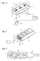
- All of the embodiment variants of the measuring arrangement according to the invention shown in FIGS. 1 to 3 have a transparent carrier element for the excitation and measuring radiation used 1, with an interface 11 the luminescence-optical sensor elements 2, 2 ' records, the excitation radiation radiated through the interface 12 and through the Interface 13 the measuring radiation is emitted.
- the interface 12 is therefore the one or more Light sources 3 and the interface 13 assigned to the detector (s) 4, 4 '.
- the direction of the excitation radiation is essentially normal to the direction of detection, but also angles from 60 to 120 ° are permissible.
- All sensor elements 2, which are preferably different Indicator materials for measuring different parameters are marked by a common sample channel 6 connected.
- the capillary sample channel 6 and its housing structure 7 are only indicated schematically.
- the sample channel can be a square, rectangular or have a substantially semicircular cross-section, with extensions in the area of the individual sensor elements 2, 2 'are permissible.
- Carrier element 1 which can be cuboidal, for example.
- the individual sensor elements 2 are arranged, respectively through the interfaces 12 and 13, respectively, the excitation radiation or the measurement radiation is detected.
- a second similar component or housing 7, in which the sample channel 6, for example, is embedded in a groove shape, can with the carrier element 1 z. B. glued or connected by other suitable means.
- FIG. 1a has separate radiation sources 3 for each of the sensor elements 2 and a detector 4 assigned on the end side, here the excitation via a device 16 takes place at different times according to the so-called multiplex method.
- Simultaneous measurement in connection with the present invention thus means Measurement of several parameters as part of a sample loading of the sample channel.
- Fig. 1b are the individual radiation sources of a side surface 12 of the carrier element assigned, the excitation of the individual sensor elements either by the evanescent Share of the excitation wave or by suitable adjustment of the refractive index in the Range of sensor spots can be done.
- the excitation radiation periodically modulated via the device 17, wherein a periodically modulated detection of the measuring radiation takes place.
- the facilities 17 and 18 are connected to a signal line 23, so that the measurement of the phase angle in the evaluation unit and / or the demodulation between excitation and measurement radiation can take place.
- FIG. 1c shows an embodiment variant in which all sensor elements 2 have a common, pulsed radiation source 3 and a common detector 4 is assigned. After the common, pulsed excitation of all sensor elements 2, the detection takes place through temporally offset measuring points or measuring windows. With this variant, however, the mean time constant of the decay time of the individual sensor elements differs significantly his.
- the detector 4 can be provided with a device 19 for the mathematical separation of the decay time functions of the individual sensor elements.
- FIG. 2 A variant of the embodiments according to FIGS. 1a to 1c is shown in FIG. 2.
- the carrier element 1 has delimited regions 15 in the area of the sensor elements 2, whose refractive index n 2 is greater than the refractive index n 1 of the actual carrier element.
- the excitation radiation can be supplied directly and / or by means of total reflection via the regions 15 with the larger refractive index n 2 .
- the fluorescence radiation emitted in all spatial directions reaches, among other things, the lateral areas of the carrier element 1 and is there derived directly and / or by means of total reflection to one of the two end faces 13 and detected by the detector 4.
- FIG. 3 A very compact variant is shown in FIG. 3.
- Each first sensor element 2 of a group of two is over A first detector 4 is assigned a first light path 20 in the carrier element 1, and each second sensor element 2 'via a second light path 21, a second detector 4'.
- Recesses 8 or opaque layers 9 can be used to block each other Light path can be used.
- the separation of the light paths of different groups of two of sensor elements 2, 2 ' can be achieved by temporally offset excitation of the individual groups of two but also done, for example, by modulated excitation and detection.
Landscapes
- Health & Medical Sciences (AREA)
- Chemical & Material Sciences (AREA)
- Immunology (AREA)
- Physics & Mathematics (AREA)
- Life Sciences & Earth Sciences (AREA)
- Analytical Chemistry (AREA)
- Biochemistry (AREA)
- General Health & Medical Sciences (AREA)
- General Physics & Mathematics (AREA)
- Nuclear Medicine, Radiotherapy & Molecular Imaging (AREA)
- Pathology (AREA)
- Chemical Kinetics & Catalysis (AREA)
- Optics & Photonics (AREA)
- Investigating, Analyzing Materials By Fluorescence Or Luminescence (AREA)
- Investigating Or Analysing Materials By The Use Of Chemical Reactions (AREA)
Description
Die Erfindung betrifft eine Meßanordnung mit zumindest einer Strahlungsquelle zur Bereitstellung einer Anregungsstrahlung, mit einem ersten lumineszenzoptischen Sensorelement, mit zumindest einem Detektor, einer Auswerteeinheit zur Detektion einer Meßstrahlung und einem für die Anregungs- und die Meßstrahlung transparenten Trägerelement, welches eine erste Grenzfläche zur Anbringung des lumineszenzoptischen Sensorelementes, eine zweite Grenzfläche zur Aufnahme der Anregungsstrahlung sowie eine dritte Grenzfläche zur Abgabe der Meßstrahlung des Sensorelementes an den Detektor aufweist, wobei die Richtung der Anregungsstrahlung mit der Detektionsrichtung einen Winkel zwischen 60° und 120°, vorzugsweise einen Winkel von im wesentlichen 90°, einschließt und der Brechungsindex des Trägerelementes größer ist, als jener der Umgebung.The invention relates to a measuring arrangement with at least one radiation source Provision of an excitation radiation, with a first luminescence optical Sensor element, with at least one detector, an evaluation unit for the detection of a Measuring radiation and a transparent for the excitation and the measuring radiation Carrier element, which has a first interface for attaching the luminescence optical Sensor element, a second interface for receiving the excitation radiation and a third interface for emitting the measuring radiation of the sensor element to the detector The direction of the excitation radiation is one with the detection direction Angles between 60 ° and 120 °, preferably an angle of essentially 90 °, includes and the refractive index of the carrier element is greater than that of the environment.
Eine Meßanordnung der eingangs genannten Art ist beispielsweise aus der AT-B 383 684 bekannt geworden. Ein transparentes Trägerelement dieser Meßanordnung mit planparallelen Begrenzungsflächen weist auf einer dieser Flächen eine Sensorschicht auf, wobei diese Sensorschicht von einer Strahlungsquelle mit Anregungsstrahlung beaufschlagt wird. Das Licht der Strahlungsquelle fällt durch eine Blendeneinrichtung auf die Sensorschicht, wobei die entstehende Meßstrahlung im wesentlichen normal zur Richtung der Anregungsstrahlung zu einem an einer seitlichen Begrenzungsfläche des Trägerelementes angeordneten Detektor abgeführt wird. Die Lichtleitung im Trägerelement erfolgt im wesentlichen durch Totalreflexion der Meßstrahlung an den Begrenzungsflächen des Trägerelementes. An der Begrenzungsfläche mit der Sensorschicht ist eine Meßgutkammer angeordnet, welche über einen Einlaß und einen Auslaß für die Probe verfügt und von der zu messenden Probe durchspült werden kann. Die Probe bzw. der zu vermessende Analyt in der Probe verändert eine optische Eigenschaft des Lumineszenzindikators in der Sensorschicht, wodurch sich die vom Detektor erfaßte Meßstrahlung in funktionaler Abhängigkeit von der Analytkonzentration ändert.A measuring arrangement of the type mentioned at the outset is, for example, from AT-B 383 684 known. A transparent support element of this measuring arrangement with plane-parallel Boundary surfaces have a sensor layer on one of these surfaces, this sensor layer is excited by a radiation source with excitation radiation. The light the radiation source falls through a diaphragm device onto the sensor layer, the resulting measuring radiation is essentially normal to the direction of the excitation radiation a detector arranged on a lateral boundary surface of the carrier element becomes. The light is guided in the carrier element essentially by total reflection the measuring radiation at the boundary surfaces of the carrier element. At the boundary surface a sensor chamber is arranged with the sensor layer, which via a Has inlet and an outlet for the sample and flushed through by the sample to be measured can be. The sample or the analyte to be measured in the sample changes an optical one Property of the luminescence indicator in the sensor layer, which differs from that of the detector detected measurement radiation changes depending on the analyte concentration.
Aus der EP-B1 0 354 895 ist ein Einwegmeßelement zur gleichzeitigen Vermessung mehrerer unterschiedlicher Probenbestandteile bekannt, welches aus einem Sensorteil und einem damit verbundenen Probennahmeteil besteht. Der Sensorteil weist einen Probenkanal auf, in welchem mehrere Sensoren angeordnet sind. Die Anregung der Sensoren bzw. die Detektion der Meßstrahlung erfolgt über Lichtleiter zu jedem einzelnen der Sensoren, wobei die Auswertung der Lichtsignale in einer nicht weiter dargestellten Anregungs- und Meßeinrichtung erfolgt.EP-B1 0 354 895 describes a disposable measuring element for the simultaneous measurement of several different sample components known, which consists of a sensor part and thus connected sampling part exists. The sensor part has a sample channel in which several sensors are arranged. The excitation of the sensors or the detection of the Measuring radiation takes place via light guides to each of the sensors, with the evaluation the light signals in an excitation and measuring device, not shown he follows.
Aus der US-A 4 968 632 ist ein Verfahren und eine Vorrichtung für die rasche Analyse einer Probe bekannt. Eine Probenkammer mit transparenten, gegenüberliegenden Wänden ist an der Innenseite mit einem Lumineszenzindikator versehen, welcher in einer Indikatorschicht angeordnet ist. Die von mehreren Lichtquellen emittierte Anregungsstrahlung gelangt durch eine transparente Wand der Meßkammer auf die Probe, beispielsweise ein zu messendes Gas, welches mit der Indikatorschicht wechselwirkt. Im Bereich der Indikatorschicht sind mehrere Filter angeordnet, welche jeweils nur einen bestimmten Anteil der Meßstrahlung herausfiltern, wobei pro Filter eine Photodiode zur Erfassung der Meßstrahlung vorgesehen ist. Aufgrund charakteristischer Änderungen in den einzelnen Spektren kann dann auf die Meßgröße geschlossen werden.From US-A 4 968 632 a method and an apparatus for the rapid analysis of a Sample known. A sample chamber with transparent, opposite walls is on the Provided on the inside with a luminescence indicator, which is arranged in an indicator layer is. The excitation radiation emitted by several light sources passes through one transparent wall of the measuring chamber on the sample, for example a gas to be measured, which interacts with the indicator layer. There are several in the area of the indicator layer Filters arranged, which each filter out only a certain proportion of the measuring radiation, one photodiode is provided per filter to detect the measuring radiation. Because of characteristic changes in the individual spectra can then be deduced from the measured variable become.
Ein Sensorelement für die gleichzeitige Bestimmung der Konzentration mehrerer Substanzen in einer Probe wird auch in der US-A 5 039 490 beschrieben. In einem mehrschichtig aufgebauten Sensorelement befinden sich nebeneinander angeordnete photosensitive Elemente und lichtemittierende Quellen, welche durch eine transparente Koppelschicht abgedeckt sind. Auf dieser Koppelschicht befindet sich die Indikatorschicht, welche ihrerseits mit einer mit der Probe in Kontakt stehenden Deckschicht abgedeckt sein kann. Das relativ kompliziert aufgebaute Sensorelement benötigt Filter oder optische Gitter, um eine Rückstreuung des Anregungslichtes in die photosensitiven Elemente zu vermeiden. Durch die Verwendung unterschiedlicher Indikatorsubstanzen für einzelne photosensitive Elemente können gleichzeitig mehrere unterschiedliche Probenbestandteile vermessen werden.A sensor element for the simultaneous determination of the concentration of several substances in a sample is also described in US-A 5,039,490. In a multi-layer structure Sensor elements are arranged side by side photosensitive elements and light-emitting sources, which are covered by a transparent coupling layer. On this coupling layer there is the indicator layer, which in turn has a the cover layer in contact with the sample can be covered. That is relatively complicated built-up sensor element requires filters or optical gratings to backscatter the excitation light to avoid in the photosensitive elements. By using different Indicator substances for individual photosensitive elements can be used simultaneously several different sample components are measured.
Weiters ist aus M.J.P. LEINER, Sensors and Actuators B29 (1995) 169 - 173 unter dem Titel "Optical sensors for in vitro blood gas analysis" eine Meßkammer zur gleichzeitigen Messung von pH, PCO2 und PO2 im Blut bekannt geworden, wobei die Meßkammer als Durchflußmeßzelle ausgebildet ist. Diese besteht im wesentlichen aus zwei Spritzgussteilen aus einem für die Anregungs- und Meßstrahlung der verwendeten lumineszenzoptischen Sensoren transparenten Plastikmaterial. An den stirnseitigen Enden der Meßzelle sind Anschlüsse für den Probenzu- bzw. Probenablauf angeformt. Der Basisteil der Meßkammer weist in einem Sensorbereich drei zylindrische Vertiefungen zur Aufnahme der Sensorelemente auf. Im Deckteil der Meßkammer befindet sich eine nutförmige Vertiefung, welche zusammen mit dem Basisteil den Meßkanal bildet, welcher in etwa 40 µl Probenvolumen aufweist. Die Anregung des Lumineszenzindikators in den einzelnen lumineszenzoptischen Sensorelementen, sowie die Detektion der Lumineszenzstrahlung erfolgt über Lichtleiter, welche auf den Basisteil der Messkammer gerichtet sind.Furthermore, from MJP LEINER, Sensors and Actuators B29 (1995) 169-173, under the title "Optical sensors for in vitro blood gas analysis", a measuring chamber for the simultaneous measurement of pH, PCO 2 and PO 2 in the blood has become known, the measuring chamber is designed as a flow measuring cell. This essentially consists of two injection molded parts made of a plastic material which is transparent for the excitation and measuring radiation of the luminescence optical sensors used. Connections for the sample inflow or outflow are formed on the front ends of the measuring cell. The base part of the measuring chamber has three cylindrical recesses for receiving the sensor elements in a sensor area. In the cover part of the measuring chamber there is a groove-shaped depression which, together with the base part, forms the measuring channel, which has a sample volume of approximately 40 μl. The excitation of the luminescence indicator in the individual luminescence-optical sensor elements, as well as the detection of the luminescence radiation takes place via light guides which are directed onto the base part of the measuring chamber.
Aufgabe der vorliegenden Erfindung ist es, ausgehend vom genannten Stand der Technik eine Meßanordnung vorzuschlagen, welche einfach und billig herzustellen ist, wobei ohne Verwendung von Filtern und optischen Gittern im Trägerelement gleichzeitig mehrere unterschiedliche Probenbestandteile vermessen werden können. Eine weitere Forderung besteht darin, das Trägerelement der Meßanordnung als Einwegelement auszubilden.The object of the present invention is based on the prior art mentioned To propose measuring arrangement, which is simple and inexpensive to manufacture, without use of filters and optical gratings in the carrier element several different at the same time Sample components can be measured. Another requirement exists in forming the support element of the measuring arrangement as a disposable element.
Diese Aufgabe wird erfindungsgemäß dadurch gelöst, daß gemäß einer ersten Ausführungsvariante auf der ersten Grenzfläche zumindest ein weiteres, vorzugsweise vom ersten unterschiedliches, durch einen gemeinsamen Probenkanal verbundenes, lumineszenzoptisches Sensorelement angeordnet ist, daß jedem Sensorelement eine separate Strahlungsquelle sowie allen Sensorelementen ein gemeinsamer Detektor zugeordnet ist, sowie daß eine elektronische Steuereinrichtungen vorgesehen ist, mit welcher die separaten Strahlungsquellen zu einer zeitlich versetzten Abgabe der Anregungsstrahlung verbunden sind (Multiplexverfahren), so daß die Trennung der Lichtwege der Meßstrahlung jedes Sensorelementes durch zeitlich versetzte Anregung der Sensorelemente erfolg.This object is achieved in that according to a first embodiment on the first interface at least one other, preferably different from the first, luminescence optical connected by a common sample channel Sensor element is arranged that each sensor element and a separate radiation source a common detector is assigned to all sensor elements, and that an electronic one Control devices are provided with which the separate radiation sources form a temporally offset delivery of the excitation radiation are connected (multiplex method), so that the separation of the light paths of the measuring radiation of each sensor element by staggered in time Success of the sensor elements.
Vorteilhafterweise wird somit nicht nur die Anregungsstrahlung durch unterschiedliche optische Lichtwege von der Meßstrahlung sondern auch die von den einzelnen Sensorelementen jeweils emittierte Meßstrahlung durch im folgenden näher beschriebene elektronische und/oder mathematische Vorrichtung bzw. Verfahren separiert. Durch diese Maßnahme kann auf optische Filter oder optische Gitterstrukturen im Trägerelement verzichtet werden.It is therefore advantageous not only for the excitation radiation to be different optical ones Light paths from the measuring radiation but also from the individual sensor elements each emitted measuring radiation by electronic described in more detail below and / or separated mathematical device or method. This measure can optical filters or optical lattice structures in the carrier element can be dispensed with.
In den beiden folgenden vorteilhaften Ausgestaltung der Erfindung ist jedem Sensorelement eine separate Strahlungsquelle sowie allen Sensorelementen ein gemeinsamer Detektor zugeordnet sein.In the following two advantageous embodiments of the invention, each sensor element a separate radiation source and all sensor elements a common detector be assigned.
Eine Ausführungsvariante zeichnet sich dadurch aus, daß eine elektronische Einrichtung zur periodischen Modulation der Anregungsstrahlung, welche mit den separaten Strahlungsquellen verbunden ist, eine Einrichtung zur periodisch modulierten Erfassung der Meßstrahlung, welche mit dem Detektor verbunden ist sowie eine Einrichtung zur Messung des Phasenwinkels und/oder der Demodulation zwischen Anregungs- und Meßstrahlung, vorgesehen ist. Die Abklingzeit bzw. deren Änderung kann somit auch aus der Demodulation, d. h. der Reduktion der Amplitude der Meßstrahlung gegenüber der Anregungsstrahlung, gewonnen werden.An embodiment variant is characterized in that an electronic device for periodic modulation of the excitation radiation, which with the separate radiation sources is connected, a device for periodically modulated measurement radiation measurement, which is connected to the detector and a device for measuring the phase angle and / or the demodulation between excitation and measurement radiation is provided. The Cooldown or its change can thus also from demodulation, ie. H. the reduction the amplitude of the measuring radiation compared to the excitation radiation.
Eine gepulste Anregung mit nachfolgender Abklingzeitmessung kann in jenen Fällen vorteilhaft angewandt werden, wo jedem Sensorelement eine separate Strahlungsquelle zugeordnet ist. Eine derartige Ausführungsvariante ist dadurch gekennzeichnet, daß eine Einrichtung zur gepulsten Anregung der Sensorelemente, welche mit den separaten Strahlungsquellen verbunden ist, sowie eine Einrichtung zur zeitaufgelösten Erfassung der Meßstrahlung, welche mit dem Detektor in Verbindung steht, vorgesehen ist.A pulsed excitation with subsequent decay time measurement can be advantageous in those cases are used where a separate radiation source is assigned to each sensor element is. Such a variant is characterized in that a device for pulsed excitation of the sensor elements, which are connected to the separate radiation sources is, and a device for time-resolved detection of the measuring radiation, which with is connected to the detector is provided.
Weiters ist in einer erfindungsgemäßen Variante vorgesehen, daß alle Sensorelemente mit einer gemeinsamen, gepulsten Strahlungsquelle sowie mit einem gemeinsamen Detektor in optischer Verbindung stehen, wobei der Detektor zur Trennung der Lichtwege der Meßstrahlung jedes Sensorelementes mit einer Einrichtung zur zeitlich versetzten Detektierung der Meßstrahlung verbunden ist. Die Trennung der Lichtwege kann auch durch eine nachgeschaltete Einheit zur mathematischen Auftrennung der Abklingzeitfunktionen der einzelnen Sensorelemente erfolgen. In dieser einfachen Ausführungsvariante kann für mehrere Sensorelemente eine Strahlungsquelle sowie ein gemeinsamer Detektor verwendet werden.Furthermore, it is provided in a variant according to the invention that all sensor elements with a common, pulsed radiation source and a common detector in are optical connection, the detector for separating the light paths of the measuring radiation each sensor element with a device for the temporally offset detection of Measuring radiation is connected. The separation of the light paths can also be followed by a Unit for the mathematical separation of the cooldown functions of the individual Sensor elements are made. In this simple embodiment variant, several sensor elements can be used a radiation source and a common detector can be used.
Weiters kann bei Ausführungsvarianten, wo alle Sensorelemente mit einem gemeinsamen Detektor in optischer Verbindung stehen, dieser Detektor auch die Abklingzeitprofile aller Sensorelemente gleichzeitig erfassen, wobei dann die Auswerteeinrichtung eine Einheit zur mathematischen Auftrennung der Abklingzeitfünktionen der einzelnen Sensorelemente aufweist. Bei dieser Ausführungsvariante ist jedoch die Zahl der Sensorelemente beschränkt und davon abhängig, inwieweit die mittleren Zeitkonstanten der Abklingzeiten der einzelnen Sensorelemente unterschiedlich sind. Gute Meßergebnisse können dann erzielt werden, wenn sich die mittleren Zeitkonstanten der Abklingzeiten zumindest um einen Faktor zwei unterscheiden.Furthermore, in the case of design variants, where all sensor elements have a common Detector in optical connection, this detector also the decay time profiles of all Detect sensor elements simultaneously, the evaluation device then being a unit for has mathematical separation of the decay time functions of the individual sensor elements. In this embodiment variant, however, the number of sensor elements is limited and depends on the extent to which the average time constant of the decay times of the individual sensor elements are different. Good measurement results can be achieved if distinguish the mean time constants of the decay times by at least a factor of two.
Das Trägerelement kann für eine Lichtleitung zwischen den Sensorelementen und dem Detektor bzw. den Detektoren mittels Totalreflexion geeignet sein. Es sind jedoch auch Ausführungsvarianten denkbar, wo zusätzlich auch die Anregungsstrahlung zwischen Lichtquelle und den Sensorelementen mittels Totalreflexion im Trägerelement geführt wird.The carrier element can be used for light conduction between the sensor elements and the Detector or the detectors by means of total reflection. However, there are also Design variants conceivable, where in addition the excitation radiation between Light source and the sensor elements is guided by means of total reflection in the carrier element.
Das Trägerelement kann in allen Ausführungsvarianten samt Sensorelementen und Probenkanal als kostengünstiges Einwegelement ausgebildet sein, dessen Grenzflächen nach dem Einlegen in ein Meßgerät als Kontaktflächen für die im Meßgerät angeordneten Strahlungsquellen bzw. Detektoren dienen.The support element can be in all design variants including sensor elements and Sample channel can be designed as an inexpensive disposable element, the interfaces of which the insertion in a measuring device as contact surfaces for those arranged in the measuring device Radiation sources or detectors are used.
Die Erfindung wird im folgenden anhand von schematischen Darstellungen näher erläutert. Es zeigen die Fig. 1a bis 1c erfindungsgemäße Meßanordnungen mit jeweils gleichem Trägerelement und unterschiedlichen Anregungs- und Detektionseinrichtungen, sowie die Fig. 2 und 3 weitere vorteilhafte Ausführungsvarianten der Erfindung.The invention is explained in more detail below with the aid of schematic representations. It 1a to 1c show measuring arrangements according to the invention, each with the same Carrier element and different excitation and detection devices, as well as the 2 and 3 further advantageous embodiments of the invention.
Alle in den Fig. 1 bis 3 dargestellten Ausführungsvarianten der erfindungsgemäßen Meßanordnung
weisen ein für die verwendete Anregungs- und Meßstrahlung transparentes Trägerelement
1 auf, wobei eine Grenzfläche 11 die lumineszenzoptischen Sensorelemente 2, 2'
aufnimmt, durch die Grenzfläche 12 die Anregungsstrahlung eingestrahlt und durch die
Grenzfläche 13 die Meßstrahlung abgegeben wird. Die Grenzfläche 12 ist daher der bzw. den
Lichtquellen 3 und die Grenzfläche 13 der bzw. den Detektoren 4, 4' zugeordnet. Die Signale
der Detektoren 4, 4' werden einer Auswerteeinheit 5 zugeführt. Die Richtung der Anregungsstrahlung
steht im wesentlichen normal auf die Detektionsrichtung, wobei jedoch auch Winkel
von 60 bis 120° zulässig sind. Alle Sensorelemente 2, welche vorzugsweise unterschiedliche
Indikatormaterialien zur Messung unterschiedlicher Parameter aufweisen, sind durch einen
gemeinsamen Probenkanal 6 verbunden. Der kapillare Probenkanal 6 sowie dessen Gehäusestruktur
7 sind nur schematisch angedeutet. Der Probenkanal kann einen quadratischen, rechteckigen
oder im wesentlichen halbkreisförmigen Querschnitt aufweisen, wobei auch Erweiterungen
im Bereich der einzelnen Sensorelemente 2, 2' zulässig sind.All of the embodiment variants of the measuring arrangement according to the invention shown in FIGS. 1 to 3
have a transparent carrier element for the excitation and measuring radiation used
1, with an
Die Ausführungen gemäß Fig. 1a bis Fig. 1c zeichnen sich durch ein sehr einfach gestaltetes
Trägerelement 1 aus, welches beispielsweise quaderförmig ausgebildet sein kann. Auf einer
der länglichen Grenzflächen 11 sind die einzelnen Sensorelemente 2 angeordnet, wobei jeweils
durch die Grenzflächen 12 bzw. 13 die Anregungsstrahlung eingestrahlt bzw. die Meßstrahlung
detektiert wird. Ein zweiter ähnlicher Bauteil bzw. Gehäuse 7, in welchem der Probenkanal
6 beispielsweise nutförmig eingelassen ist, kann mit dem Trägerelement 1 z. B.
verklebt oder durch andere geeignete Mittel verbunden sein.1a to 1c are distinguished by a very simple
Die Ausführungsvariante Fig. 1a verfügt über separate Strahlungsquellen 3 für jedes der Sensorelemente
2 und einen stimseitig zugeordneten Detektor 4, wobei hier die Anregung über
eine Einrichtung 16 zeitlich versetzt nach dem sogenannten Multiplexverfahren erfolgt.
Gleichzeitige Messung im Zusammenhang mit der vorliegenden Erfindung bedeutet somit die
Messung mehrerer Parameter im Rahmen einer Probenbeschickung des Probenkanals.The embodiment variant FIG. 1a has
In Fig. 1b sind die einzelnen Strahlungsquellen einer Seitenfläche 12 des Trägerelementes
zugeordnet, wobei die Anregung der einzelnen Sensorelemente entweder durch den evaneszenten
Anteil der Anregungswelle oder durch geeignete Anpassung des Brechungsindex im
Bereich der Sensorspots erfolgen kann. Bei dieser Ausführungsvariante wird die Anregungsstrahlung
über die Einrichtung 17 periodisch moduliert, wobei über die Einrichtung 18 eine
periodisch modulierte Erfassung der Meßstrahlung erfolgt. Die Einrichtungen 17 und 18 sind
mit einer Signalleitung 23 verbunden, sodaß in der Auswerteeinheit die Messung des Phasenwinkels
und/oder der Demodulation zwischen Anregungs- und Meßstrahlung erfolgen kann.In Fig. 1b are the individual radiation sources of a
Schließlich zeigt Fig. 1c eine Ausführungsvariante, bei der allen Sensorelementen 2 eine gemeinsame,
gepulste Strahlungsquelle 3 sowie ein gemeinsamer Detektor 4 zugeordnet ist.
Nach der gemeinsamen, gepulsten Anregung aller Sensorelemente 2 erfolgt die Detektierung
durch zeitlich versetzte Meßpunkte bzw. Meßfenster. Bei dieser Variante sollte jedoch die
mittlere Zeitkonstante der Abklingzeit der einzelnen Sensorelemente signifikant unterschiedlich
sein. Dem Detektor 4 kann eine Einrichtung 19 zur mathematischen Auftrennung der Abklingzeitfunktionen
der einzelnen Sensorelemente nachgeschaltet sein.Finally, FIG. 1c shows an embodiment variant in which all
Eine Variante der Ausführungen nach Fig. 1a bis 1c wird in Fig. 2 dargestellt. Das Trägerelement
1 weist im Bereich der Sensorelemente 2 abgegrenzte Bereiche 15 auf, deren Brechungsindex
n2 größer ist als der Brechungsindex n1 des eigentlichen Trägerelementes. Über
die Bereiche 15 mit dem größeren Brechungsindex n2 kann die Zufuhr der Anregungsstrahlung
direkt und/oder mittels Totalreflexion erfolgen. Die in alle Raumrichtungen emittierte
Fluoreszenzstrahlung gelangt unter anderem in die seitlichen Bereiche des Trägerelementes 1
und wird dort direkt und/oder mittels Totalreflexion an eine der beiden Stirnflächen 13 abgeleitet
und vom Detektor 4 erfaßt. A variant of the embodiments according to FIGS. 1a to 1c is shown in FIG. 2. The
Eine sehr kompakte Ausführungsvariante wird in Fig. 3 dargestellt. Hier werden jeweils zwei
Sensorelemente 2, 2' zu Zweiergruppen zusammengefaßt, wobei jeder dieser Gruppen eine
separate Strahlungsquelle 3 zugeordnet ist. Auf diese Art können in einer kompakten
Bauform, beispielsweise bis zu acht unterschiedliche Sensorelemente, durch bis zu vier
Leuchtdioden angeregt werden. Jedem ersten Sensorelement 2 einer Zweiergruppe ist über
einen ersten Lichtweg 20 im Trägerelement 1 ein erster Detektor 4 zugeordnet, und jedem
zweiten Sensorelement 2' über einen zweiten Lichtweg 21 ein zweiter Detektor 4'. Ausnehmungen
8 oder lichtundurchlässige Schichten 9 können zur Sperrung des jeweiligen anderen
Lichtweges verwendet werden. Die Trennung der Lichtwege unterschiedlicher Zweiergruppen
von Sensorelementen 2, 2' kann durch zeitlich versetzte Anregung der einzelnen Zweiergruppen
aber auch beispielsweise durch modulierte Anregung und Detektion erfolgen.A very compact variant is shown in FIG. 3. Here are two each
Claims (7)
- Measuring device comprising at least one radiation source 3 for the supplying of excitation radiation, and a first luminescence-optical sensor element 2, and at least one detector 4 and an evaluation unit 5 for the detection of measurement radiation, and a supporting element 1 transparent to excitation and measurement radiation, which has a first boundary face 11 holding the luminescence-optical sensor element 2, and a second boundary face 12 picking up the excitation radiation, and a third boundary face 13 transmitting the measurement radiation of the sensor element 2 to the detector 4, the direction of the excitation radiation forming an angle of 60° to 120°, and preferably an angle of essentially 90°, with the direction of detection, and the refractive index n1 of the supporting element being greater than that of the environment, characterised in that on the first boundary face 11 is located at least one further luminescence-optical sensor element 2, which preferably differs from the first sensor element and is connected thereto by a common sample channel 6, and that each sensor element 2 is assigned a separate radiation source 3 and all sensor elements 2 are assigned one common detector 4, and further that an electronic control means 16 is provided to which the separate radiation sources 3 are connected in order to permit the time-sequenced emission of excitation radiation.
- Measuring device comprising at least one radiation source 3 for the supplying of excitation radiation, and a first luminescence-optical sensor element 2, and at least one detector 4 and an evaluation unit 5 for the detection of measurement radiation, and a supporting element 1 transparent to excitation and measurement radiation, which has a first boundary face 11 holding the luminescence-optical sensor element 2, and a second boundary face 12 picking up the excitation radiation, and a third boundary face 13 transmitting the measurement radiation of the sensor element 2 to the detector 4, the direction of the excitation radiation forming an angle of 60° to 120°, and preferably an angle of essentially 90°, with the direction of detection, and the refractive index n1 of the supporting element being greater than that of the environment, characterised in that on the first boundary face 11 is located at least one further luminescence-optical sensor element 2, which preferably differs from the first sensor element and is connected thereto by a common sample channel 6, and that each sensor element 2 is assigned a separate radiation source 3 and all sensor elements 2 are assigned one common detector 4, and further that an electronic means 17 is provided for periodic modulation of the excitation radiation, which is connected to the separate radiation sources 3, and that the detector 4 is connected to a device 18 for periodically modulated detection of the measurement radiation, and further that a device is provided for measuring the phase angle and/or the demodulation between excitation and measurement radiation.
- Measuring device comprising at least one radiation source 3 for the supplying of excitation radiation, and a first luminescence-optical sensor element 2, and at least one detector 4 and an evaluation unit 5 for the detection of measurement radiation, and a supporting element 1 transparent to excitation and measurement radiation, which has a first boundary face 11 holding the luminescence-optical sensor element 2, and a second boundary face 12 picking up the excitation radiation, and a third boundary face 13 delivering the measurement radiation of the sensor element 2 to the detector 4, the direction of the excitation radiation forming an angle of 60° to 120°, and preferably an angle of essentially 90°, with the direction of detection, and the refractive index n1 of the supporting element being greater than that of the environment, characterised in that on the first boundary face 11 is located at least one further luminescence-optical sensor element 2, which preferably differs from the first sensor element and is connected thereto by a common sample channel 6, and that each sensor element 2 is assigned a separate radiation source 3 and all sensor elements 2 are assigned one common detector 4, and further that a device is provided for pulsed excitation of the sensor elements 2, which is connected to the separate radiation sources 3, and further a device for time-resolved detection of the measurement radiation, which is connected to the detector 4.
- Measuring device according to any of claims 1 to 3, characterised in that the supporting element 1 features delimited regions 15 in the area of each sensor element 2, whose refractive index n2 is greater than the refractive index n1 of the supporting element 1 outside of said regions, the regions 15 with refractive index n2 being used to feed in excitation radiation, and the remaining regions of the supporting element 1 with refractive index n1 to carry off measurement radiation.
- Measuring device comprising at least one radiation source 3 for the supplying of excitation radiation, and a first luminescence-optical sensor element 2, and at least one detector 4 and an evaluation unit 5 for the detection of measurement radiation, and a supporting element 1 transparent to excitation and measurement radiation, which has a first boundary face 11 holding the luminescence-optical sensor element 2, and a second boundary face 12 picking up the excitation radiation, and a third boundary face 13 delivering the measurement radiation of the sensor element 2 to the detector 4, the direction of the excitation radiation forming an angle of 60° to 120°, and preferably an angle of essentially 90°, with the direction of detection, and the refractive index n1 of the supporting element being greater than that of the environment, characterised in that on the first boundary face 11 is located at least one further luminescence-optical sensor element 2, which preferably differs from the first sensor element and is connected thereto by a common sample channel 6, and that one common, pulsed radiation source 3 is provided for all sensor elements 2 as well as a device for time-sequenced detection of the measurement radiation, all sensor elements 2 being optically connected to a common detector 4.
- Measuring device comprising at least one radiation source 3 for the supplying of excitation radiation, and a first luminescence-optical sensor element 2, and at least one detector 4 and an evaluation unit 5 for the detection of measurement radiation, and a supporting element 1 transparent to excitation and measurement radiation, which has a first boundary face 11 holding the luminescence-optical sensor element 2, and a second boundary face 12 picking up the excitation radiation, and a third boundary face 13 delivering the measurement radiation of the sensor element 2 to the detector 4, the direction of the excitation radiation forming an angle of 60° to 120°, and preferably an angle of essentially 90°, with the direction of detection, and the refractive index n1 of the supporting element being greater than that of the environment, characterised in that on the first boundary face 11 is located at least one further luminescence-optical sensor element 2, which preferably differs from the first sensor element and is connected thereto by a common sample channel 6, and that the detector 4 includes a device for simultaneous recording of the decay time profiles of all sensor elements 2, and the evaluation unit 5 includes a subunit 19 for mathematical splitting of the decay time functions of the individual sensor elements 2, all sensor elements 2 being optically connected to one common detector 4.
- Measuring device comprising at least one radiation source 3 for the supplying of excitation radiation, and a first luminescence-optical sensor element 2, and at least one detector 4 and an evaluation unit 5 for the detection of measurement radiation, and a supporting element 1 transparent to excitation and measurement radiation, which has a first boundary face 11 holding the luminescence-optical sensor element 2, and a second boundary face 12 picking up the excitation radiation, and a third boundary face 13 delivering the measurement radiation of the sensor element 2 to the detector 4, the direction of the excitation radiation forming an angle of 60° to 120°, and preferably an angle of essentially 90°, with the direction of detection, and the refractive index n1 of the supporting element being greater than that of the environment, characterised in that on the first boundary face 11 is located at least one further luminescence-optical sensor element 2,2', which preferably differs from the first sensor element and is connected thereto by a common sample channel 6, and that the sensor elements 2,2' are combined into pairs, each pair being assigned a separate radiation source 3, and that the evaluation unit 5 is connected to two detectors 4, 4', each first sensor element 2 of a pair being assigned a first detector 4 via a first light path 20 in the supporting element 1, and each second sensor element 2' being assigned a second detector 4' via a second light path 21 in the supporting element 1, and that a device is provided for the purpose of time-sequenced excitation of the individual pairs.
Applications Claiming Priority (3)
| Application Number | Priority Date | Filing Date | Title |
|---|---|---|---|
| AT0038396A AT403745B (en) | 1996-02-29 | 1996-02-29 | MEASURING ARRANGEMENT WITH A TRANSPARENT ELEMENT FOR EXCITING AND MEASURING RADIATION |
| AT38396 | 1996-02-29 | ||
| EP97890024A EP0793090B1 (en) | 1996-02-29 | 1997-02-12 | Measuring system with probe carrier transparent for excitation and measurement beam |
Related Parent Applications (2)
| Application Number | Title | Priority Date | Filing Date |
|---|---|---|---|
| EP97890024.9 Division | 1997-02-12 | ||
| EP97890024A Division EP0793090B1 (en) | 1996-02-29 | 1997-02-12 | Measuring system with probe carrier transparent for excitation and measurement beam |
Publications (2)
| Publication Number | Publication Date |
|---|---|
| EP0987539A1 EP0987539A1 (en) | 2000-03-22 |
| EP0987539B1 true EP0987539B1 (en) | 2001-08-29 |
Family
ID=3489146
Family Applications (2)
| Application Number | Title | Priority Date | Filing Date |
|---|---|---|---|
| EP97890024A Expired - Lifetime EP0793090B1 (en) | 1996-02-29 | 1997-02-12 | Measuring system with probe carrier transparent for excitation and measurement beam |
| EP99124388A Expired - Lifetime EP0987539B1 (en) | 1996-02-29 | 1997-02-12 | Measuring device with at least one excitation source |
Family Applications Before (1)
| Application Number | Title | Priority Date | Filing Date |
|---|---|---|---|
| EP97890024A Expired - Lifetime EP0793090B1 (en) | 1996-02-29 | 1997-02-12 | Measuring system with probe carrier transparent for excitation and measurement beam |
Country Status (5)
| Country | Link |
|---|---|
| US (1) | US5779978A (en) |
| EP (2) | EP0793090B1 (en) |
| JP (1) | JP3054756B2 (en) |
| AT (1) | AT403745B (en) |
| DE (2) | DE59702435D1 (en) |
Cited By (2)
| Publication number | Priority date | Publication date | Assignee | Title |
|---|---|---|---|---|
| US9273353B2 (en) | 1998-05-16 | 2016-03-01 | Life Technologies Corporation | Instrument for monitoring polymerase chain reaction of DNA |
| US9285318B2 (en) | 1999-05-17 | 2016-03-15 | Applied Biosystems, Llc | Optical instrument including excitation source |
Families Citing this family (45)
| Publication number | Priority date | Publication date | Assignee | Title |
|---|---|---|---|---|
| CA2255599C (en) * | 1996-04-25 | 2006-09-05 | Bioarray Solutions, Llc | Light-controlled electrokinetic assembly of particles near surfaces |
| WO1998023945A1 (en) * | 1996-11-27 | 1998-06-04 | Optical Analytic Inc. | Perimeter light detection apparatus for enhanced collection of radiation |
| DE19725050C2 (en) * | 1997-06-13 | 1999-06-24 | Fraunhofer Ges Forschung | Arrangement for the detection of biochemical or chemical substances by means of fluorescent light excitation and method for their production |
| US6710870B1 (en) | 1998-02-05 | 2004-03-23 | Novartis Ag | Method and device for measuring luminescence |
| AU759974B2 (en) * | 1998-05-16 | 2003-05-01 | Applied Biosystems, Llc | Instrument for monitoring polymerase chain reaction of DNA |
| US7498164B2 (en) | 1998-05-16 | 2009-03-03 | Applied Biosystems, Llc | Instrument for monitoring nucleic acid sequence amplification reaction |
| US6373577B1 (en) | 1998-05-20 | 2002-04-16 | Graffinity Pharmaceutical Design Gmbh | Surface plasmon resonance sensor for the simultaneous measurement of a plurality of samples in fluid form |
| ES2251244T3 (en) | 1998-11-20 | 2006-04-16 | Graffinity Pharmaceutical Design Gmbh | MEASUREMENT DEVICE AND MEASUREMENT METHOD FOR PARALLEL READING OF SPR SENSORS. |
| US7410793B2 (en) * | 1999-05-17 | 2008-08-12 | Applera Corporation | Optical instrument including excitation source |
| US7423750B2 (en) * | 2001-11-29 | 2008-09-09 | Applera Corporation | Configurations, systems, and methods for optical scanning with at least one first relative angular motion and at least one second angular motion or at least one linear motion |
| US7387891B2 (en) * | 1999-05-17 | 2008-06-17 | Applera Corporation | Optical instrument including excitation source |
| WO2000075644A1 (en) * | 1999-06-05 | 2000-12-14 | Zeptosens Ag | Sensor platform and method for analysing multiple analytes |
| US6514277B1 (en) | 1999-06-11 | 2003-02-04 | Photonics Research Ontario | Fiber optic multitasking probe |
| US6771376B2 (en) * | 1999-07-05 | 2004-08-03 | Novartis Ag | Sensor platform, apparatus incorporating the platform, and process using the platform |
| AU5824300A (en) | 1999-07-05 | 2001-01-22 | Novartis Ag | Sensor platform, apparatus incorporating the platform, and process using the platform |
| US7167615B1 (en) | 1999-11-05 | 2007-01-23 | Board Of Regents, The University Of Texas System | Resonant waveguide-grating filters and sensors and methods for making and using same |
| AT410600B (en) * | 1999-12-02 | 2003-06-25 | Hoffmann La Roche | MEASURING CHAMBER WITH LUMINESCENCE OPTICAL SENSOR ELEMENTS |
| BR0016711A (en) * | 1999-12-24 | 2002-09-03 | Roche Diagnostics Gmbh | Test Element Analysis System |
| CA2400207A1 (en) * | 2000-02-18 | 2001-08-23 | Aclara Biosciences, Inc. | Multiple-site reaction device and method |
| DE10008006C2 (en) | 2000-02-22 | 2003-10-16 | Graffinity Pharm Design Gmbh | SPR sensor and SPR sensor arrangement |
| GB2368903A (en) * | 2000-11-08 | 2002-05-15 | Proimmune Ltd | Analysis of biological and biochemical assays |
| DE60231960D1 (en) * | 2001-01-23 | 2009-05-28 | Univ Dublin City | LUMINESCENCE DETECTOR |
| DE60220497T2 (en) | 2001-01-26 | 2008-01-31 | Biocal Technology, Inc., Irvine | OPTICAL DETECTION IN A MULTI-CHANNEL BIOSEPARATION SYSTEM |
| WO2002066965A2 (en) * | 2001-02-19 | 2002-08-29 | Scientific Generics Limited | Assay apparatus, assay method and probe array for use in same |
| US6767733B1 (en) * | 2001-10-10 | 2004-07-27 | Pritest, Inc. | Portable biosensor apparatus with controlled flow |
| US6870165B2 (en) * | 2001-10-19 | 2005-03-22 | Biocal Technology, Inc. | Multi-color multiplexed analysis in a bio-separation system |
| FI115343B (en) * | 2001-10-22 | 2005-04-15 | Filtronic Lk Oy | Internal multi-band antenna |
| US7635588B2 (en) * | 2001-11-29 | 2009-12-22 | Applied Biosystems, Llc | Apparatus and method for differentiating multiple fluorescence signals by excitation wavelength |
| US20040020993A1 (en) * | 2001-12-28 | 2004-02-05 | Green Larry R. | Method for luminescent identification and calibration |
| US7179654B2 (en) * | 2002-03-18 | 2007-02-20 | Agilent Technologies, Inc. | Biochemical assay with programmable array detection |
| US7029631B2 (en) * | 2002-04-19 | 2006-04-18 | Agilent Technologies, Inc. | Apparatus for improved light collection |
| US20040060987A1 (en) * | 2002-05-07 | 2004-04-01 | Green Larry R. | Digital image analysis method for enhanced and optimized signals in fluorophore detection |
| EP2775291B1 (en) | 2002-05-17 | 2016-01-13 | Life Technologies Corporation | Apparatus for differentiating multiple fluorescence signals by excitation wavelength |
| US6861251B2 (en) | 2003-02-24 | 2005-03-01 | Pritest, Inc. | Translucent solid matrix assay device for microarray analysis |
| JP3824233B2 (en) * | 2003-09-01 | 2006-09-20 | セイコーエプソン株式会社 | Biosensor and biosensor manufacturing method |
| SE529254C2 (en) * | 2005-06-17 | 2007-06-12 | Aamic Ab | Optical test system |
| KR20080027392A (en) * | 2005-07-14 | 2008-03-26 | 나노디텍 코포레이션 | Microfluidic devices and methods of preparing and using the same |
| US7846390B2 (en) * | 2006-03-30 | 2010-12-07 | King Fahd University Of Petroleum And Minerals | Apparatus and method for measuring concentrations of fuel mixtures using depth-resolved laser-induced fluorescence |
| US7750316B2 (en) * | 2006-05-10 | 2010-07-06 | Dublin City University | Polymer biochip for detecting fluorescence |
| AT507994B1 (en) * | 2009-01-19 | 2011-05-15 | Smart Medical Solutions Gmbh | Measurement arrangement for determining at least one parameter of a sample liquor |
| FR2979689B1 (en) | 2011-09-02 | 2014-09-12 | Commissariat Energie Atomique | DEVICE FOR LIGHTING A LIGHT-SOURCE OBJECT HAVING AN ORGAN FOR REMOVING A PORTION OF LIGHT, APPLICATION FOR MEASURING SOURCE FLOW VARIATIONS |
| FR2979703B1 (en) | 2011-09-02 | 2014-01-24 | Commissariat Energie Atomique | DEVICE FOR OPTICALLY MEASURING MATERIALS USING LIGHT MULTIPLEXING |
| GB2495703A (en) * | 2011-10-12 | 2013-04-24 | Crowcon Detection Instr Ltd | Optical sensor without wavelength filter |
| AT512498B1 (en) * | 2012-06-06 | 2013-09-15 | Joanneum Res Forschungsgmbh | Opto-chemical sensor |
| DE102016115607A1 (en) | 2016-08-23 | 2018-03-01 | B. Braun Melsungen Ag | Measuring system with reduced crosstalk for measuring fluid parameters |
Family Cites Families (18)
| Publication number | Priority date | Publication date | Assignee | Title |
|---|---|---|---|---|
| US3604927A (en) * | 1966-11-16 | 1971-09-14 | Block Engineering | Total reflection fluorescence spectroscopy |
| US4399099A (en) * | 1979-09-20 | 1983-08-16 | Buckles Richard G | Optical fiber apparatus for quantitative analysis |
| ATE143289T1 (en) * | 1984-06-13 | 1996-10-15 | Applied Research Systems | APPARATUS USED IN CHEMICAL TESTING PROCEDURES |
| AT383684B (en) * | 1984-09-17 | 1987-08-10 | Avl Verbrennungskraft Messtech | ARRANGEMENT FOR FLUORESCENT OPTICAL MEASUREMENT OF SUBSTANCE CONCENTRATIONS IN A SAMPLE |
| EP0175352B1 (en) * | 1984-09-19 | 1991-06-12 | Siemens-Elema AB | Method and device for rapidly ascertaining the parameters of a sample medium |
| ATE77483T1 (en) * | 1986-04-23 | 1992-07-15 | Avl Medical Instr Ag | SENSOR ELEMENT FOR DETERMINING SUBSTANCE CONCENTRATIONS. |
| JPH083464B2 (en) * | 1987-04-30 | 1996-01-17 | ダイキン工業株式会社 | Optical measuring device |
| AT393565B (en) * | 1988-08-09 | 1991-11-11 | Avl Verbrennungskraft Messtech | DISPOSABLE MEASURING ELEMENT |
| JPH0526810A (en) * | 1991-07-23 | 1993-02-02 | Hamamatsu Photonics Kk | Device for detecting fluorescence from fine particles |
| US5370842A (en) * | 1991-11-29 | 1994-12-06 | Canon Kabushiki Kaisha | Sample measuring device and sample measuring system |
| US5418371A (en) * | 1993-02-01 | 1995-05-23 | Aslund; Nils R. D. | Apparatus for quantitative imaging of multiple fluorophores using dual detectors |
| ATE209782T1 (en) * | 1993-05-18 | 2001-12-15 | Univ Utah Res Found | DEVICE AND METHOD FOR HOMOGENEOUS MULTIANALYTE IMMUNO ASSAY |
| US5424841A (en) * | 1993-05-28 | 1995-06-13 | Molecular Dynamics | Apparatus for measuring spatial distribution of fluorescence on a substrate |
| US5439647A (en) * | 1994-02-25 | 1995-08-08 | Fiberchem, Inc. | Chip level waveguide sensor |
| US5577137A (en) * | 1995-02-22 | 1996-11-19 | American Research Corporation Of Virginia | Optical chemical sensor and method using same employing a multiplicity of fluorophores contained in the free volume of a polymeric optical waveguide or in pores of a ceramic waveguide |
| US5672515A (en) * | 1995-09-12 | 1997-09-30 | Optical Sensors Incorporated | Simultaneous dual excitation/single emission fluorescent sensing method for PH and pCO2 |
| US5623561A (en) * | 1995-09-29 | 1997-04-22 | Georgia Tech Research Corporation | Integrated optic interferometric sensor |
| US5694215A (en) * | 1996-03-04 | 1997-12-02 | Carver; David R. | Optical array and processing electronics and method therefor for use in spectroscopy |
-
1996
- 1996-02-29 AT AT0038396A patent/AT403745B/en not_active IP Right Cessation
-
1997
- 1997-02-07 US US08/797,249 patent/US5779978A/en not_active Expired - Lifetime
- 1997-02-12 DE DE59702435T patent/DE59702435D1/en not_active Expired - Lifetime
- 1997-02-12 EP EP97890024A patent/EP0793090B1/en not_active Expired - Lifetime
- 1997-02-12 EP EP99124388A patent/EP0987539B1/en not_active Expired - Lifetime
- 1997-02-12 DE DE59704487T patent/DE59704487D1/en not_active Expired - Lifetime
- 1997-02-28 JP JP9044501A patent/JP3054756B2/en not_active Expired - Lifetime
Cited By (2)
| Publication number | Priority date | Publication date | Assignee | Title |
|---|---|---|---|---|
| US9273353B2 (en) | 1998-05-16 | 2016-03-01 | Life Technologies Corporation | Instrument for monitoring polymerase chain reaction of DNA |
| US9285318B2 (en) | 1999-05-17 | 2016-03-15 | Applied Biosystems, Llc | Optical instrument including excitation source |
Also Published As
| Publication number | Publication date |
|---|---|
| ATA38396A (en) | 1997-09-15 |
| DE59702435D1 (en) | 2000-11-16 |
| AT403745B (en) | 1998-05-25 |
| US5779978A (en) | 1998-07-14 |
| EP0793090A1 (en) | 1997-09-03 |
| DE59704487D1 (en) | 2001-10-04 |
| EP0793090B1 (en) | 2000-10-11 |
| EP0987539A1 (en) | 2000-03-22 |
| JP3054756B2 (en) | 2000-06-19 |
| JPH09325116A (en) | 1997-12-16 |
Similar Documents
| Publication | Publication Date | Title |
|---|---|---|
| EP0987539B1 (en) | Measuring device with at least one excitation source | |
| DE69836490T2 (en) | IMPROVED ELECTROCHEMICAL CELL | |
| EP0263805B1 (en) | Sensor element for ascertaining the concentrations of substances | |
| EP1238274B1 (en) | Test element analysis system with infrared detector | |
| EP0244394B1 (en) | Sensor element for determining the concentration of substances | |
| DE19615366B4 (en) | Method and device for detecting physical, chemical, biological or biochemical reactions and interactions | |
| EP0736767A1 (en) | Optical detection device for analytical measurements of chemical substances | |
| DE19544501A1 (en) | Device for light reflection measurements | |
| EP0163847A2 (en) | Interferential refractometer | |
| DE10163657B4 (en) | Apparatus and method for investigating thin films | |
| EP0376110A2 (en) | Test strip analysing system | |
| DE4223840C2 (en) | Refractometer | |
| DE102008033214A1 (en) | Method for optically determining a measured variable of a measuring medium | |
| WO1992010740A1 (en) | Method and device for the continuous, reversible measurement of the concentration of a chemical species | |
| EP1061371B1 (en) | Method and device for controlling the liquid absorption of an analysing element test layer | |
| EP2717044A1 (en) | Method for detecting analytes | |
| AT507994B1 (en) | Measurement arrangement for determining at least one parameter of a sample liquor | |
| DE102007006153A1 (en) | Optical gas sensor arrangement for use in motor vehicle, has detector device detecting changed radiation intensity in end region of reaction section, and producing output signal in dependence of presence of analyte in reaction path | |
| DE10324973B4 (en) | Arrangement and method for the optical detection of chemical, biochemical molecules and / or particles contained in samples | |
| DE4125036C1 (en) | Fibre=optic sensor for measuring refractive index of liq. or gas - measures reflection at free end of optical fibre coated with material of high refractive index using lock-in amplifiers | |
| DE19816359A1 (en) | Optical structural change detector for surface of moving part, especially adhesive layer | |
| DE19751403A1 (en) | Process and assembly for determining absorption, fluorescence, scatter and refraction of liquids, gases and solids | |
| EP0473940B1 (en) | Photometric device with scattering light trap | |
| DE19920184A1 (en) | Simultaneous detection of diffuse, specular reflections from specimens involves coupling radiation from receiver plane into space between receiver, optical planes, using two receivers | |
| EP0538664A2 (en) | Method and device for determining optical spectral shifts caused by physical or chemical effects |
Legal Events
| Date | Code | Title | Description |
|---|---|---|---|
| PUAI | Public reference made under article 153(3) epc to a published international application that has entered the european phase |
Free format text: ORIGINAL CODE: 0009012 |
|
| AC | Divisional application: reference to earlier application |
Ref document number: 793090 Country of ref document: EP |
|
| AK | Designated contracting states |
Kind code of ref document: A1 Designated state(s): DE FR GB |
|
| AX | Request for extension of the european patent |
Free format text: AL;LT;LV;RO;SI |
|
| 17P | Request for examination filed |
Effective date: 20000325 |
|
| AKX | Designation fees paid |
Free format text: DE FR GB |
|
| GRAG | Despatch of communication of intention to grant |
Free format text: ORIGINAL CODE: EPIDOS AGRA |
|
| 17Q | First examination report despatched |
Effective date: 20001220 |
|
| GRAG | Despatch of communication of intention to grant |
Free format text: ORIGINAL CODE: EPIDOS AGRA |
|
| GRAH | Despatch of communication of intention to grant a patent |
Free format text: ORIGINAL CODE: EPIDOS IGRA |
|
| GRAH | Despatch of communication of intention to grant a patent |
Free format text: ORIGINAL CODE: EPIDOS IGRA |
|
| GRAA | (expected) grant |
Free format text: ORIGINAL CODE: 0009210 |
|
| AC | Divisional application: reference to earlier application |
Ref document number: 793090 Country of ref document: EP |
|
| AK | Designated contracting states |
Kind code of ref document: B1 Designated state(s): DE FR GB |
|
| RAP1 | Party data changed (applicant data changed or rights of an application transferred) |
Owner name: F. HOFFMANN-LA ROCHE AG |
|
| GBT | Gb: translation of ep patent filed (gb section 77(6)(a)/1977) |
Effective date: 20010829 |
|
| REF | Corresponds to: |
Ref document number: 59704487 Country of ref document: DE Date of ref document: 20011004 |
|
| ET | Fr: translation filed | ||
| REG | Reference to a national code |
Ref country code: GB Ref legal event code: IF02 |
|
| PLBE | No opposition filed within time limit |
Free format text: ORIGINAL CODE: 0009261 |
|
| STAA | Information on the status of an ep patent application or granted ep patent |
Free format text: STATUS: NO OPPOSITION FILED WITHIN TIME LIMIT |
|
| 26N | No opposition filed | ||
| REG | Reference to a national code |
Ref country code: FR Ref legal event code: PLFP Year of fee payment: 20 |
|
| PGFP | Annual fee paid to national office [announced via postgrant information from national office to epo] |
Ref country code: DE Payment date: 20160302 Year of fee payment: 20 |
|
| PGFP | Annual fee paid to national office [announced via postgrant information from national office to epo] |
Ref country code: FR Payment date: 20160125 Year of fee payment: 20 Ref country code: GB Payment date: 20160127 Year of fee payment: 20 |
|
| REG | Reference to a national code |
Ref country code: DE Ref legal event code: R071 Ref document number: 59704487 Country of ref document: DE |
|
| REG | Reference to a national code |
Ref country code: GB Ref legal event code: PE20 Expiry date: 20170211 |
|
| PG25 | Lapsed in a contracting state [announced via postgrant information from national office to epo] |
Ref country code: GB Free format text: LAPSE BECAUSE OF EXPIRATION OF PROTECTION Effective date: 20170211 |