EP0987485A2 - Vorrichtung zum Bewickeln eines Rohrstranges mit Korrosionsschutzband - Google Patents
Vorrichtung zum Bewickeln eines Rohrstranges mit Korrosionsschutzband Download PDFInfo
- Publication number
- EP0987485A2 EP0987485A2 EP99113817A EP99113817A EP0987485A2 EP 0987485 A2 EP0987485 A2 EP 0987485A2 EP 99113817 A EP99113817 A EP 99113817A EP 99113817 A EP99113817 A EP 99113817A EP 0987485 A2 EP0987485 A2 EP 0987485A2
- Authority
- EP
- European Patent Office
- Prior art keywords
- chassis
- pipe
- slewing ring
- rollers
- tube
- Prior art date
- Legal status (The legal status is an assumption and is not a legal conclusion. Google has not performed a legal analysis and makes no representation as to the accuracy of the status listed.)
- Withdrawn
Links
- 238000004804 winding Methods 0.000 title description 16
- 238000005260 corrosion Methods 0.000 claims abstract description 17
- 230000007797 corrosion Effects 0.000 abstract description 9
- 238000010276 construction Methods 0.000 description 2
- 239000004033 plastic Substances 0.000 description 2
- 229920003023 plastic Polymers 0.000 description 2
- 230000001681 protective effect Effects 0.000 description 2
- 230000009467 reduction Effects 0.000 description 2
- 239000004698 Polyethylene Substances 0.000 description 1
- 235000004443 Ricinus communis Nutrition 0.000 description 1
- 240000000528 Ricinus communis Species 0.000 description 1
- QVGXLLKOCUKJST-UHFFFAOYSA-N atomic oxygen Chemical compound [O] QVGXLLKOCUKJST-UHFFFAOYSA-N 0.000 description 1
- 230000008901 benefit Effects 0.000 description 1
- 229920005549 butyl rubber Polymers 0.000 description 1
- 230000008859 change Effects 0.000 description 1
- 238000005253 cladding Methods 0.000 description 1
- 239000011248 coating agent Substances 0.000 description 1
- 238000000576 coating method Methods 0.000 description 1
- 150000001875 compounds Chemical class 0.000 description 1
- 230000000694 effects Effects 0.000 description 1
- 239000003792 electrolyte Substances 0.000 description 1
- 239000007769 metal material Substances 0.000 description 1
- 238000000034 method Methods 0.000 description 1
- 229910052760 oxygen Inorganic materials 0.000 description 1
- 239000001301 oxygen Substances 0.000 description 1
- -1 polyethylene Polymers 0.000 description 1
- 229920000573 polyethylene Polymers 0.000 description 1
- 230000008569 process Effects 0.000 description 1
- 230000008439 repair process Effects 0.000 description 1
- 238000005096 rolling process Methods 0.000 description 1
- 239000002689 soil Substances 0.000 description 1
- XLYOFNOQVPJJNP-UHFFFAOYSA-N water Substances O XLYOFNOQVPJJNP-UHFFFAOYSA-N 0.000 description 1
Images

Classifications
-
- B—PERFORMING OPERATIONS; TRANSPORTING
- B65—CONVEYING; PACKING; STORING; HANDLING THIN OR FILAMENTARY MATERIAL
- B65H—HANDLING THIN OR FILAMENTARY MATERIAL, e.g. SHEETS, WEBS, CABLES
- B65H81/00—Methods, apparatus, or devices for covering or wrapping cores by winding webs, tapes, or filamentary material, not otherwise provided for
- B65H81/06—Covering or wrapping elongated cores
- B65H81/08—Covering or wrapping elongated cores by feeding material obliquely to the axis of the core
-
- F—MECHANICAL ENGINEERING; LIGHTING; HEATING; WEAPONS; BLASTING
- F16—ENGINEERING ELEMENTS AND UNITS; GENERAL MEASURES FOR PRODUCING AND MAINTAINING EFFECTIVE FUNCTIONING OF MACHINES OR INSTALLATIONS; THERMAL INSULATION IN GENERAL
- F16L—PIPES; JOINTS OR FITTINGS FOR PIPES; SUPPORTS FOR PIPES, CABLES OR PROTECTIVE TUBING; MEANS FOR THERMAL INSULATION IN GENERAL
- F16L58/00—Protection of pipes or pipe fittings against corrosion or incrustation
- F16L58/02—Protection of pipes or pipe fittings against corrosion or incrustation by means of internal or external coatings
- F16L58/04—Coatings characterised by the materials used
- F16L58/10—Coatings characterised by the materials used by rubber or plastics
- F16L58/1054—Coatings characterised by the materials used by rubber or plastics the coating being placed outside the pipe
- F16L58/1063—Coatings characterised by the materials used by rubber or plastics the coating being placed outside the pipe the coating being a sheet wrapped around the pipe
Definitions
- handsets can also be used robustly within a Pipe trench proven, as for example from DE-PS 23 60 700 are known. Such handsets are, however, at Large pipes that a person in handling such Can no longer grasp the device, can no longer be used.
- Basic structure consist of an annular support frame, the encloses the pipe to be wound and which is closed with the help of Support rollers that roll all around the pipe surface, is rotatably held on the tube to be wound.
- Support frames are one or more unwinding devices for the anti-corrosion tapes are arranged in a similar manner work like the aforementioned handheld device.
- Such Devices are used particularly in the construction of new pipelines, if the pipe string to be laid is continuously with a Corrosion protection wrapping should be wrapped, however even if only the welded connections between two, with pipe sections provided by the factory to be wrapped in a corrosion protection covering.
- WO 92/14090 describes a device for applying anti-corrosion tapes known for large diameter pipes, where a claw-like gripping around the pipe to be wound Equipment carrier with winding device for the to be wrapped Protective tape is provided, which with an endless, the circumference of the drive belt is provided, the by a drive connected to the equipment rack with the unwinder around the pipe.
- a device is particularly for wrapping around Welds from two adjacent pipe sections Pipes with a smaller diameter can be used because it is quick can be moved from weld to weld.
- the invention has for its object a device create, like they also for winding complete pipe strings, especially from pipes with diameters of over 600 mm is required, which is simplified in structure and handling is.
- a device for wrapping a pipe in particular a pipe string with corrosion protection tape, which has a chassis that can be driven Rollers is provided and on the tube in the longitudinal direction is movable and on which a tube comprising the pipe to be wound
- the slewing ring is drivably mounted, with at least an unwinding device provided with a tape reel is.
- Such a device has the advantage that them on a finished welded one to be laid in a pipe trench Pipe string can be moved in the longitudinal direction, only a sufficient width and depth Free space must be provided.
- rollers on the chassis are arranged so that this on the apex area of the pipe is supported.
- more rollers laterally on Pipe are arranged adjacent to the chassis.
- the undercarriage is provided with a drive motor, over which the running wheels of the undercarriage and the slewing ring in a predeterminable ratio of the driving speed of the Chassis can be driven to the speed of the slewing ring.
- a drive motor over which the running wheels of the undercarriage and the slewing ring in a predeterminable ratio of the driving speed of the Chassis can be driven to the speed of the slewing ring.
- the to the apex area of the winding rollers associated with the drive motor are in operative connection.
- the slewing ring is designed to be divisible. This configuration offers the possibility that after removing a Part of the slewing ring either the device as a whole placed on an existing pipe string can be. After placing the device on the Pipe string becomes the relevant section of the slewing ring reinstalled and firmly connected.
- the invention of the slewing ring on support rollers on the chassis is rotatably mounted.
- This arrangement also offers the possibility the slewing ring interchangeable with the chassis connect, with a corresponding change in distance the support rollers to each other slewing rings with different Diameters can be used.
- the slewing ring is designed as a ring gear and that the toothing of the slewing ring via a drive pinion is connected to the drive motor.
- the Gearing can be in the simplest form on the outside be arranged on the slewing ring. But it is also possible that Provide smooth outer surface of the slewing ring and the Inner circumference of the slewing ring next to each other at an axial distance both the running surfaces for the support rollers and the toothing to provide.
- the undercarriage with a lateral drawbar is on the actuators for control the driving functions are arranged.
- the drawbar has the possibility that the operator to the side of the device while observing the running winding process the device in the pipe trench can lead.
- For pipe strings with a factory coating are provided and where only the welds between two pipe sections can then be wrapped using the drawbar the device from a winding point to the other winding point either moved by hand or can also be moved via the travel drive, whereby then the drive for the slewing ring must be disengaged.
- the chassis on the A counterweight is arranged at the opposite end of the slewing ring. This counterweight makes the relatively high weight the slewing ring with the attached winding device, and the torque that occurs when wrapping the pipe balanced.
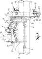
- Fig. 1 there is the illustrated embodiment essentially on one built on tubular elements Chassis 1, which is provided with rollers 2, which Undercarriage on the top of a winding area Support pipe string 3.
- rollers 2 which Undercarriage on the top of a winding area Support pipe string 3.
- casters 4 arranged on the chassis 1 so that they are on the side of the pipe string 3 concerns. The arrangement is such that this Rollers 4 with respect to those arranged in the apex area Casters 2 slightly below the median plane of the Pipe string 3 are arranged.
- rollers 2 arranged in the apex area are each via control arms 5 on the chassis 1 with a central axis 6 articulated so that the appropriate altitude 7 of the chassis 1 opposite the rolling plane for the rollers 2 is adjustable.
- a tube to be wound provided from above U-shaped holding frame 11, the is connected to a plurality of support rollers 12, the plane of rotation in a cross-sectional plane of the pipe string 3 to be wound is aligned.
- a slewing ring 13 On these support rollers 12 is a slewing ring 13, here for example one with external teeth 14
- the slewing ring is axially fixed.
- the toothing 14 the turntable 13 is operatively connected to a drive pinion 15, which in turn with the drive motor 10 via a actuatable disconnect clutch is connected.
- Slewing ring 13 is designed to be divisible and expediently into unequal sections.
- the smaller section 13.1 can be removed after loosening the corresponding closures 16 be so that the device as a whole from above on the can be put on winding pipe string. Subsequently section 13.1 is reinserted and over the Closures 16 firmly with the larger section of the slewing ring 13 connected.
- Fig. 2 are the unwinding devices only schematic and compared to the illustration acc. Fig. 1 shown offset by 90 °. The basic structure of such a unwinding device 18 is explained in more detail with reference to FIG. 3.
- the two unwinding device 18 are now on the slewing ring 13 attached that the on the pipe surface of the pipe string 3rd applied, schematically indicated corrosion protection tapes 19 when the slewing ring 13 is actuated in two positions with a given overlap on the pipe surface be applied.
- the elastic-plastic Deformability of the anti-corrosion tapes to be applied it is sufficient to have one smooth and per corrosion protection tape distortion-free overlap of the wrapping between 25 and 75 mm to effect.
- the width of the overlap is corresponding Setting the relationship between driving speed of the chassis in the longitudinal direction of the pipe and the rotational speed of the slewing ring with the unwinding devices determined around the pipe.
- the unwinding device 18 consists essentially of a Carrier 20, with a winding core 21 with attached Tape reel 22 is provided.
- the winding core 21 is a winding roll 23 assigned, when pulling off the anti-corrosion tape between the individual layers of the wrap of the reel with the release film when pulling off the Corrosion protection tape wound up from this separately and in an orderly manner becomes.
- the winding roller 23 is driven via a belt drive not shown here intermediate slip clutch.
- adjustable friction brake 26 becomes the initial value of the Tension set for the tape to be wound.
- the friction force is then provided with a contact roller 27 Arm 28 proportional to the reduction in the winding diameter reduced so that there is essentially a constant Winding pull results.
- FIG. 2 there is one on the chassis 1 laterally protruding, provided with a handle 29 Guide drawbar 30 arranged.
- On the handle 29 are (here schematically shown) each have a clutch lever 31 for the travel drive and a clutch lever 32 for driving the slewing ring 13 and a throttle lever 33 for adjusting the driving speed intended.
Landscapes
- Engineering & Computer Science (AREA)
- General Engineering & Computer Science (AREA)
- Mechanical Engineering (AREA)
- Storing, Repeated Paying-Out, And Re-Storing Of Elongated Articles (AREA)
- Protection Of Pipes Against Damage, Friction, And Corrosion (AREA)
Abstract
Description
- Fig. 1
- eine Vorrichtung in Seitenansicht,
- Fig. 2
- eine Stirnansicht,
- Fig. 3
- eine Aufsicht auf eine Abspulvorrichtung.
Claims (11)
- Vorrichtung zum Umwickeln eines Rohres (3), insbesondere eines Rohrstranges, mit Korrosionsschutzband (19), die ein Fahrwerk (1) aufweist, das mit antreibbaren Laufrollen (2, 4) versehen und auf dem Rohr (3) in Längsrichtung verfahrbar ist, und an dem ein das zu bewickelnde Rohr (3) umfassender Drehkranz (13) antreibbar gelagert ist, der mit wenigstens einer, mit einer Bandspule versehenen Abspulvorrichtung (18) verbunden ist.
- Vorrichtung nach Anspruch 1, dadurch gekennnzeichnet, daß Laufrollen (2) zur Abstützung des Fahrwerks (1) auf dem Scheitelbereich des Rohres (3) angeordnet sind.
- Vorrichtung nach Anspruch 1 oder 2, dadurch gekennzeichnet, daß Laufrollen (4) seitlich am Rohr (3) anliegend am Fahrwerk (1) angeordnet sind.
- Vorrichtung nach einem der Ansprüche 1 bis 3, dadurch gekennzeichnet, daß das Fahrwerk (1) mit einem Antriebsmotor (10) versehen ist, über den Laufrollen (2) des Fahrwerks (1) und der Drehkranz (13) in einem vorgebbaren Verhältnis von Fahrgeschwindigkeit des Fahrwerks (1) zur Drehzahl des Drehkranzes (13) antreibbar sind.
- Vorrichtung nach einem der Ansprüche 1 bis 4, dadurch gekennzeichnet, daß die dem Scheitelbereich des zu bewickelnden Rohres (3) zugeordneten Laufrollen (2) mit dem Antriebsmotor (10) in Wirkverbindung stehen.
- Vorrichtung nach einem der Ansprüche 1 bis 5, dadurch gekennzeichnet, daß die dem Scheitelbereich des zu bewickelnden Rohres (3) zugeordneten Laufrollen (2) im Abstand zum Fahrwerk (1) höhenverstellbar mit dem Fahrwerk (1) verbunden sind.
- Vorrichtung nach einem der Ansprüche 1 bis 6, dadurch gekennzeichnet, daß der Drehkranz (13) teilbar ausgebildet ist.
- Vorrichtung nach einem der Ansprüche 1 bis 7, dadurch gekennzeichnet, daß der Drehkranz (13) über Stützrollen (12) am Fahrwerk (1) drehbar gelagert ist.
- Vorrichtung nach einem der Ansprüche 1 bis 8, dadurch gekennzeichnet, daß der Drehkranz (13) als Zahnkranz ausgebildet ist und daß die Verzahnung (14) des Drehkranze4s (13) über ein Antriebsritzel (15) mit dem Antriebsmotor (10) in Verbindung steht.
- Vorrichtung nach einem der Ansprüche 1 bis 9, dadurch gekennzeichnet, daß das Fahrwerk (1) mit einer seitlich abstehenden Führdeichsel (30) versehen ist, an der die Betätigungseinrichtungen (31, 32, 33) zur Steuerung der Fahrfunktionen angeordnet sind.
- Vorrichtung nach einem der Ansprüche 1 bis 10, dadurch gekennzeichnet, daß am Fahrwerk (1) an dem dem Drehkranz (13) abgekehrten Ende ein Gegengewicht (34) angeordnet ist.
Applications Claiming Priority (2)
| Application Number | Priority Date | Filing Date | Title |
|---|---|---|---|
| DE19842531 | 1998-09-17 | ||
| DE1998142531 DE19842531A1 (de) | 1998-09-17 | 1998-09-17 | Vorrichtung zum Bewickeln eines Rohrstranges mit Korrosionsschutzband |
Publications (2)
| Publication Number | Publication Date |
|---|---|
| EP0987485A2 true EP0987485A2 (de) | 2000-03-22 |
| EP0987485A3 EP0987485A3 (de) | 2001-05-30 |
Family
ID=7881234
Family Applications (1)
| Application Number | Title | Priority Date | Filing Date |
|---|---|---|---|
| EP99113817A Withdrawn EP0987485A3 (de) | 1998-09-17 | 1999-07-15 | Vorrichtung zum Bewickeln eines Rohrstranges mit Korrosionsschutzband |
Country Status (2)
| Country | Link |
|---|---|
| EP (1) | EP0987485A3 (de) |
| DE (1) | DE19842531A1 (de) |
Cited By (3)
| Publication number | Priority date | Publication date | Assignee | Title |
|---|---|---|---|---|
| TR200000885A3 (tr) * | 2000-03-31 | 2001-10-22 | Socotherm S.R.L. | Metal borularin kaynakli baglantilarinin bulunduklari yerde asinmaya karsi korunmasi için yöntem ve tertibat. |
| CN111236602A (zh) * | 2020-02-28 | 2020-06-05 | 浙江省交通规划设计研究院有限公司 | 一种防腐施工平台 |
| CN114060645A (zh) * | 2022-01-14 | 2022-02-18 | 胜利新大新材料股份有限公司 | 一种管道修复缠绕装置 |
Family Cites Families (3)
| Publication number | Priority date | Publication date | Assignee | Title |
|---|---|---|---|---|
| US2302196A (en) * | 1941-02-24 | 1942-11-17 | Jesse S Downs | Pipe cleaning machine |
| US4069088A (en) * | 1976-11-22 | 1978-01-17 | Midcon Pipeline Equipment Co. | Pipe wrapping apparatus |
| US5417786A (en) * | 1993-04-12 | 1995-05-23 | Denman; George W. | Apparatus and method for coating and wrapping pipe |
-
1998
- 1998-09-17 DE DE1998142531 patent/DE19842531A1/de not_active Withdrawn
-
1999
- 1999-07-15 EP EP99113817A patent/EP0987485A3/de not_active Withdrawn
Cited By (3)
| Publication number | Priority date | Publication date | Assignee | Title |
|---|---|---|---|---|
| TR200000885A3 (tr) * | 2000-03-31 | 2001-10-22 | Socotherm S.R.L. | Metal borularin kaynakli baglantilarinin bulunduklari yerde asinmaya karsi korunmasi için yöntem ve tertibat. |
| CN111236602A (zh) * | 2020-02-28 | 2020-06-05 | 浙江省交通规划设计研究院有限公司 | 一种防腐施工平台 |
| CN114060645A (zh) * | 2022-01-14 | 2022-02-18 | 胜利新大新材料股份有限公司 | 一种管道修复缠绕装置 |
Also Published As
| Publication number | Publication date |
|---|---|
| EP0987485A3 (de) | 2001-05-30 |
| DE19842531A1 (de) | 2000-03-23 |
Similar Documents
| Publication | Publication Date | Title |
|---|---|---|
| DE2346139C2 (de) | Vorrichtung zum Abdecken eines Beckens, insbesondere eines Schwimmbeckens, mit einer auf einem Wagen gelagerten Wickel-Trommel | |
| DE1531167C3 (de) | Manipulator | |
| DE60008576T2 (de) | Kraftausgleichsvorrichtung für eine zweiseilenwinde und winde mit solcher vorrichtung | |
| DE2902116A1 (de) | Vorrichtung zum austausch des regelstab-antriebs in einem kernreaktor | |
| DE202013101350U1 (de) | Vorrichtung zum Auf- oder Abwickeln von flächigem Bahnenmaterial | |
| EP0790210B1 (de) | Vorrichtung zum Aufnehmen und Abziehen eines biegeelastischen, strangförmigen Materials | |
| EP0255573A1 (de) | Trag- oder Spannseil mit einer Ummantelung sowie Verfahren und Vorrichtung zum Herstellen eines solchen Seiles | |
| EP0987485A2 (de) | Vorrichtung zum Bewickeln eines Rohrstranges mit Korrosionsschutzband | |
| DE2325295A1 (de) | Verfahren und vorrichtung zur herstellung von betonrohren | |
| CH668761A5 (de) | Einrichtung zum aufwickeln eines kontinuierlich anfallenden schuppenstromes von biegsamen flaechengebilden zu einem wickel. | |
| EP0522127B1 (de) | Vorrichtung zur behandlung von rohroberflächen | |
| DE2645838B2 (de) | Vorrichtung zum Aufwickeln von mehreren Verstärkungsbändern auf einen zylindrischen Körper großer Länge | |
| CH657084A5 (de) | Rollabdeckung einer fuehrungsbahn fuer einen schlitten an einer werkzeugmaschine. | |
| DE2550373C2 (de) | Ziehscheibentrommel für Mehrfachdrahtziehmaschinen | |
| DE2951030A1 (de) | Vorrichtung zum bearbeiten, insbesondere zum bewickeln der oberflaechen von langgestreckten, zylindrischen koerpern | |
| DE2349439A1 (de) | Vorrichtung an schlingflorbobinenwicklern | |
| DE19902977C2 (de) | Beschichtungsanlage für die Innenbeschichtung von Rohren und ähnlichen langgestreckten Hohlkörpern | |
| EP0471931B1 (de) | Wickelvorrichtung | |
| DE3441434A1 (de) | Ziehdrahthaspelanordnung mit, einen doppeltrommelblock bildender obertrommel und untertrommel | |
| DE1779437B2 (de) | Vorrichtung zum Zuliefern von fortlaufenden Reifengewebebahnen zu einer Schrägschneidemaschine. Ausscheidung aus: 1729725 | |
| DE884710C (de) | Angelwinde, insbesondere zur Spinnfischerei | |
| DE4314096A1 (de) | Vorrichtung zum Auf- und Ausrollen eines Bodenbelages | |
| WO2006032370A2 (de) | Entmistungseinrichtung mit einer motorisch angetrieben seiltrommel sowie seiltrommelanordnung und antriebsvorrichtung hierfür | |
| EP0945346A1 (de) | Vorrichtung zum Sammeln von langgestrecktem Material | |
| DE1484553C (de) | Gerat zum Antrieb von Verdichtungswal zen od dgl zum Verdichten von Abhangen od dgl |
Legal Events
| Date | Code | Title | Description |
|---|---|---|---|
| PUAI | Public reference made under article 153(3) epc to a published international application that has entered the european phase |
Free format text: ORIGINAL CODE: 0009012 |
|
| AK | Designated contracting states |
Kind code of ref document: A2 Designated state(s): DE FR IT NL |
|
| AX | Request for extension of the european patent |
Free format text: AL;LT;LV;MK;RO;SI |
|
| PUAL | Search report despatched |
Free format text: ORIGINAL CODE: 0009013 |
|
| AK | Designated contracting states |
Kind code of ref document: A3 Designated state(s): AT BE CH CY DE DK ES FI FR GB GR IE IT LI LU MC NL PT SE |
|
| AX | Request for extension of the european patent |
Free format text: AL;LT;LV;MK;RO;SI |
|
| RIC1 | Information provided on ipc code assigned before grant |
Free format text: 7F 16L 55/18 A, 7B 65H 81/08 B, 7F 16L 58/16 B |
|
| 17P | Request for examination filed |
Effective date: 20010818 |
|
| 17Q | First examination report despatched |
Effective date: 20011107 |
|
| AKX | Designation fees paid |
Free format text: DE FR IT NL |
|
| GRAH | Despatch of communication of intention to grant a patent |
Free format text: ORIGINAL CODE: EPIDOS IGRA |
|
| STAA | Information on the status of an ep patent application or granted ep patent |
Free format text: STATUS: THE APPLICATION HAS BEEN WITHDRAWN |
|
| 18W | Application withdrawn |
Effective date: 20021128 |