EP0986677B1 - Verbesserter geotextilbehälter und sein produktionsverfahren - Google Patents
Verbesserter geotextilbehälter und sein produktionsverfahren Download PDFInfo
- Publication number
- EP0986677B1 EP0986677B1 EP98926131A EP98926131A EP0986677B1 EP 0986677 B1 EP0986677 B1 EP 0986677B1 EP 98926131 A EP98926131 A EP 98926131A EP 98926131 A EP98926131 A EP 98926131A EP 0986677 B1 EP0986677 B1 EP 0986677B1
- Authority
- EP
- European Patent Office
- Prior art keywords
- container
- sheet
- elongated
- sack
- stitching
- Prior art date
- Legal status (The legal status is an assumption and is not a legal conclusion. Google has not performed a legal analysis and makes no representation as to the accuracy of the status listed.)
- Expired - Lifetime
Links
Images




Classifications
-
- E—FIXED CONSTRUCTIONS
- E02—HYDRAULIC ENGINEERING; FOUNDATIONS; SOIL SHIFTING
- E02B—HYDRAULIC ENGINEERING
- E02B3/00—Engineering works in connection with control or use of streams, rivers, coasts, or other marine sites; Sealings or joints for engineering works in general
- E02B3/04—Structures or apparatus for, or methods of, protecting banks, coasts, or harbours
-
- E—FIXED CONSTRUCTIONS
- E02—HYDRAULIC ENGINEERING; FOUNDATIONS; SOIL SHIFTING
- E02B—HYDRAULIC ENGINEERING
- E02B3/00—Engineering works in connection with control or use of streams, rivers, coasts, or other marine sites; Sealings or joints for engineering works in general
- E02B3/04—Structures or apparatus for, or methods of, protecting banks, coasts, or harbours
- E02B3/12—Revetment of banks, dams, watercourses, or the like, e.g. the sea-floor
- E02B3/122—Flexible prefabricated covering elements, e.g. mats, strips
- E02B3/127—Flexible prefabricated covering elements, e.g. mats, strips bags filled at the side
Definitions
- the present invention relates to the art of geotextile containers of the type for maintaining fill material.
- Geotextile containers adapted to serve as receptacles for soil, aggregate or other fill material are utilized in a variety of applications.
- elongated geotextile containers such as the bags that are disclosed in U.S. Patent No. 3,957,098 are often utilized in a body of water, such as a bay or a river, to facilitate control of erosion.
- This document discloses the features of the preamble of claims 1 and 12.
- Such bags are formed of two layers of rectangular fabric overlying each other. Each long edge of each layer is double-stitched with lock stitches to the opposed long edge of the other layer.
- an elongated container of this type may be situated to extend generally in parallel, perpendicular or at various angles with respect to the shoreline.
- Such a container may be filled with material dredged from the bottom of the body of water to provide weight to maintain the container in position.
- the area between the container and the shoreline may be backfilled with soil to effectively extend the shoreline farther out into the body of water.
- Containers of this type may also be used as a receptacle for contaminated material.
- An elongated geotextile container may have a length of up to about 615 m (2,000 feet) or more.
- the circumference will generally depend on the desired barrier height, but a circumference of about 14 m (45 feet) or more is also not unusual.
- the hydrostatic pressure on the outside of a submerged container must be overcome by the dredging pumps that are used to fill the container in order to displace the water atop and inside the container.
- the pressure applied by these pumps, as well as the weight of the fill inserted into the container will result in outwardly directed forces that stress the geotextile fabric and the seams that join the sheets of the fabric composing the container.
- the rupture strength of the geotextile material composing each sheet in the container structure can be on the order of 450 kg (1000 pounds) of force, depending on a number of factors. These factors include the polymer composition of the fabric, the weave, and the denier of the fibers in the fabric.
- the rupture strength of each of the seams that connects adjacent sheets of geotextile material composing the container is believed to be on the order of 50% of the strength of the geotextile fabric composing the sheet and depends upon the type of seam, the polymer composing the fabric, the polymer composing the sewing thread, the denier of the sewing thread, and the type of stitch made with the sewing thread. Accordingly, the seams are the weakest link in the construction of the container. The strength of the seams determines the maximum force to which the container can be subjected, before the container will burst and thus fail.
- a bag defining an inner cavity permits the fill material to be contained therein.
- the bag is constructed of at least two elongated rectangular sheets of a flexible material opposed to one another and sewn along the opposed long edges to form at least two axial seams and sewn along the opposed short edges to form at least one. end seam at a closed end. The closed end is back-folded into the inner cavity to form a pouch.
- An outer surface of the bag thus defines an inner surface of the pouch.
- an inner surface of the bag defines an outer surface of the pouch.
- At least one anchor object is positioned in the pouch and tied off by a clamping mechanism situated about a neck portion of the pouch. As a result, the pouch is closed and the anchor object is maintained on the inside thereof. Due to this construction, an axially outward force imparted by the fill material will be directed against the inner surface of the bag instead of directly against the end seam in the closed end. However, this solution does not address the adverse effect of the radially directed forces upon the longitudinal seams of the container.
- EP-A-0364059 discloses the features of the preamble of claims 4 and 15. In particular this document discloses an outwardly facing helical seam of two parallel rows of stitches through overlying lengthwise edges of a single sheet of geotextile material. This is similarly deficient.
- Still another alternative relies on a circular loom to produce a fabric in a continuous tubular shape without any longitudinal seam.
- This alternative also has its limitations.
- the tubular fabric woven by such circular looms does not have the large circumference that is desired.
- Such circular looms are themselves more expensive than a conventional loom.
- Such circular looms cannot weave some types of synthetic yarns that are desirable for forming the heavier and stronger fabrics, which are desirable for their strength and for the larger circumference applications. This is due to the inability of a circular loom to weave a fabric composed of yarns that are relatively thick and/or stiff.
- US-A-490103 discloses a grain sack of natural burlap material.
- the present invention recognizes and addresses the foregoing disadvantages, and others, of prior art constructions and methods. Accordingly, it is an object of the present invention to provide an improved geotextile container and method of making same.
- an improved geotextile container of the type for maintaining fill material includes a geotextile fabric configured into a tubular shape and having stitched seams.
- the geotextile fabric can be either permeable or non-permeable to water, as the application for the container demands.
- Each seam, both longitudinal and end, that joins adjacent sheets of geotextile material is formed in part by the flaps disposed along the border region near the respective edges of the adjacent sheets.
- a line of stitching is sewn through the opposed flaps to form a stitched flange that forms part of that seam of the container.
- the flange can be desirably formed as in a butt seam (also known as a "prayer” seam), or a "J" seam, or a butterfly seam.
- the stitching can take any of a number of forms, including for example a single needle stitch, or an over edge (serge) stitch, or a double lock stitch.
- Each such stitched flange is disposed with the stitching disposed inside the container.
- a container is formed from a single sheet of geotextile material that is furled into a tubular shape with a helical seam along the length thereof instead of one or more longitudinal straight seams.
- This helical seam desirably takes the form described above with the flange and stitching disposed inside the inner cavity of the container.
- This helical seam further strengthens the container by acting as might a reinforcing rope wound around the container along the length thereof.
- more than one sheet can be furled side-by-side into a single tubular shape and have each of their adjacent side edges joined by an helical seam so that the container has more than one parallel helical seam.
- An alternative container embodiment with a helical seam along the length thereof has an inner liner or an outer shell having one or more longitudinal straight seams formed of the inwardly disposed sewn fabric flanges.
- the helical seams resist one set of stresses and the longitudinal seams resist another set of stresses so that the combination of the longitudinal seams and the helical seams provides a stronger overall container.
- Yet another embodiment of the container of the present invention includes a geotextile container with at least two layers of geotextile material.
- An inner layer of geotextile material has a first helical seam that corkscrews in one direction.
- An outer layer of geotextile material surrounds the inner layer and has a second helical seam that corkscrews in a second direction that is out of phase with the direction of the first helical seam of the inner layer.
- the one helical seam is normal to the other helical seam and thus intersects the other helical seam as each winds around its respective layer of geotextile material.
- the pitch of the first helical seam is generally out of phase with the pitch of the second helical seam.
- the two helical seams further strengthen the container by acting as might two oppositely wound reinforcing ropes wrapped around the container along the length thereof in opposite directions.
- Each helical seam resists stresses in a different region of the container so that the combination provides a stronger overall container.
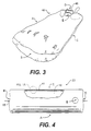
- FIG. 4 A preferred embodiment of a geotextile container in accordance with the present invention is shown in Fig. 4 in the form of an elongated tubular geotextile bag that is represented generally by the numeral 20.
- Bag 20 has a pair of opposed sides labeled A and C and a pair of opposed ends labeled B and D. Bag 20 is made in accordance with the steps illustrated schematically in Figs. 1-3 for example.
- a single sheet embodiment could be made or a plurality of elongated sheets of geotextile material could be joined together and used as a single sheet.
- two sheets 21 and 31 are shown for the sake of making the explanation of the construction easier to understand.
- the geotextile material that forms each of a first sheet 21, a second sheet 31, and any additional sheets in the construction is woven from synthetic fibers such as nylon, polypropylene, polyester, polyethylene or any combination of the foregoing fibers.
- Each resulting sheet desirably is formed such that it can withstand forces appropriate to the application for which the resulting container is intended to be used. Thus, a rupture strength of 90 kg (200 pounds) will suffice for some applications, while other applications will require the sheet to withstand on the order of 450 kg (1000 pounds) without rupturing.
- Each sheet of geotextile material has an elongated first side edge and an elongated first end edge that is contiguous with the elongated first side edge.
- each sheet further has an elongated second side edge that is contiguous with the elongated first end edge.
- the elongated second side edge is disposed generally opposite the elongated first side edge.
- Each sheet also has a second end edge that is contiguous with each of the first side edge and the second side edge.
- the second end edge is also disposed generally opposite the first side edge.
- a first sheet 21 of geotextile material is disposed with respect to a second sheet 31 of geotextile material so that a first side edge 23 of first sheet 21 is generally aligned with a first side edge 33 of second sheet 31.
- a first border region near first side edge 23 is disposed to oppose and touch a second border region near first side edge 33 of second sheet 31 so that both sheets 21, 31 are touching one another along at least their respective first and second border regions near their respective first side edges 23, 33.
- first border region near first side edge 23 of first sheet 21 is folded back upon itself to form a first flap 24 of a doubled thickness of geotextile fabric.
- second border region near first side edge 33 of second sheet 31 is folded back upon itself to form a second flap 34 of a doubled thickness of geotextile fabric.
- Each respective flap 24, 34 of first sheet 21 and second sheet 31 consists of a pair of legs, namely, an opposed leg and a free leg.
- a first opposed leg 25 of first sheet 21 is disposed in contact with a second opposed leg 35 of second sheet 31 along their lengths.
- First flap 24 then has its free leg 26 disposed to face what is presently the outside surface of first sheet 21. Accordingly, free leg 26 is disposed to face away from the opposed second sheet 31 of geotextile material. Similarly, second flap 34 then has its free leg 36 disposed to face what is presently the outside of second sheet 31, i.e., away from the opposed first sheet 21 of geotextile material.
- a means is provided for joining the sheets along their opposed border regions to form at least part of a seam.
- this joining means includes a first line of stitching, which is generally designated by the numeral 40 in Fig. 1A and schematically by the dashed line designated 40 in Fig. 13A.
- First line of stitching 40 is applied through both opposed touching flaps 24, 34 to join first sheet 21 and second sheet 31 and to form a first sewn stitched flange, which is generally designated by the numeral 41 in Figs. 1A and 13A.
- first flange 41 is composed of four thicknesses of geotextile material and forms part of what is sometimes known as a butterfly seam. As shown in Fig.
- first line of stitching 40 is disposed in the border near respective first side edges 23, 33 of first sheet 21 and second sheet 31. As shown in Fig. 1A, first line of stitching 40 desirably is formed as a plurality of double lock stitches that are sewn through flange 41.
- seam described above is a butterfly seam
- other types of seams can be used in accordance with the present invention, both for the seam described above and the other seams to be described below.
- the other types of seams suitable for the present invention desirably are multi-layer seams that include a flange 41.
- Two examples are a butt seam (also known as a "prayer” seam) and a "J" seam.
- a butt seam that joins a first sheet 21 to a second sheet 31 includes a first opposed leg 25 in contact with a second opposed leg 35, and stitching, which is schematically represented by the dashed lines designated by the number 40.
- stitching which is schematically represented by the dashed lines designated by the number 40.
- a "J" seam that joins a first sheet 21 to a second sheet 31 includes a first opposed leg 25 in contact with a second opposed leg 35, and stitching, which is schematically represented by the dashed lines designated by the number 40.
- the "J" seam also includes a first free leg 26 and a second free leg 36.
- the seams shown in the views of Figs. 13B and 13C are in an orientation comparable to the view shown in Fig. 13 in that the seam is flattened against the joined sheets of material as would occur when the geotextile container is filled with the fill material.
- the stitching 40 can take any of a number of forms, including for example a single needle stitch, or an over edge (serge) stitch, or a double lock stitch such as shown in Fig. 1A.
- the above sewing procedure is repeated with a second side edge 22 of first sheet 21, a second side edge 32 of second sheet 31, and at least a second line of stitching forming a second flange 42.
- the application of the second line of stitching results in a flange configured the same as first flange 41 shown in Fig. 1A for example.
- the resulting structure (not shown in the Figs.) is a sewn tubular structure open at each opposite end with a pair of sewn flanges 41, 42 along the respective opposite sides C, A of the length of the tubular sleeve (not shown in the Figs.).
- the sewn flanges 41, 42 extend with the respective free edges 43, 44 of the flanges 41, 42 pointing away from the outside surface of the tubular structure.
- first sheet 21 and second sheet 31 are then repeated with the respective first end edges of first sheet 21 and second sheet 31 and at least a third line of stitching.
- the result is a sewn flange 45 at a first closed end designated by the letter "B."
- the application of the third line of stitching results in a flange 45 configured the same as first flange 41 shown in Fig. 1A for example.
- Flange 45 extends between and is contiguous with the sewn flanges 41, 42 along the opposite sides of the resulting structure, which becomes open at one end and closed at one opposite end to form a sack structure 48.
- the sewn flange 45 of the closed end also extends with the free edge 49 thereof pointing away from the outside of sack 48.
- one of the sides of sack 48 is schematically indicated by the letter “A”
- the opposite side of sack 48 is schematically indicated by the letter “C”
- the open end of sack 48 is schematically indicated by the letter "D.”
- a port hole is defined through first sheet 21 by an opening indicated generally by the letter "E."
- Port hole E is desirably formed near the open end D of sack 48.
- sack 48 is everted.
- the closed end B of sack 48 is pulled from inside the sack toward the open end D of sack 48.
- closed end B of sack 48 is pulled completely out and through open end D of sack 48 until sack 48 is turned completely inside out so that all of the flanges 41, 42, 45 and their respective lines of stitching become disposed inside sack 48, as shown in Figs. 4 and 13 (flange 41 only) for example.
- This also disposes sewn flanges 41, 42, 45 so that their respective free edges 43, 44, 49 point toward the central longitudinal axis 15 (Fig. 2) of sack 48.
- the open second end D of sack 48 is now closed in a manner that disposes the closure seam inside the resulting closed sack structure.
- the second end edges at second end D of sack 48 are pulled through port hole E to the outside of sack 48.
- the end border region near the second end edge of each sheet is folded back upon itself to form a flap of a doubled thickness of fabric (as shown in Figs. 1A and 13 for example). These flaps are opposed to face against each other along the lengths of their opposed legs.
- a flap of a doubled thickness of fabric as shown in Figs. 1A and 13 for example.
- a fourth line of stitching is applied through both opposed touching flaps to join first and second sheets 21, 31 and form a fourth sewn stitched flange 46 of four thicknesses of geotextile material.
- This fourth line of stitching is disposed in the border near the respective second end edges of first sheet 21 and second sheet 31.
- the application of the fourth line of stitching results in a flange 46 configured as first flange 41 shown in Fig. 1A for example.
- the fourth line of stitching desirably is formed as a plurality of double lock stitches through the quadruple thickness flange in the border region near the respective second end edges of each first and second sheet.
- this fourth line of stitching is applied to join the second end edges near the border portion thereof while these second end edges are exposed outside of sack 48 via port hole E. In this way, the fourth line of stitching closes second end D of sack 48. Once the closure is accomplished, the second end edges and fourth line of stitching composing fourth sewn flange 46 are pushed back through port hole E into the inner cavity of the resulting closed sack structure.
- bag 20 has an inner cavity 16, and the flanges 41, 42, 45, 46 form the portion of the seams of bag 20 that face inside inner cavity 16.
- the solid fill material will apply an outwardly directed force on the inside surface of bag 20. It is believed that this outwardly directed force will be directed against each sewn flange and the line of stitching therein along a line that is perpendicular to one of the two free legs of one of the flaps forming the flange.
- the fill material 18 will apply an outwardly directed force along a line that is perpendicular to free leg 36 of the flap forming flange 41.
- the sewn fabric flanges 41, 42, 45, 46 so oriented, it is believed that the solid fill material 18 flattens each flange against the inside surface of the container and thereby directs the outwardly directed stress forces from the weight of the fill material, against the free leg that forms the side of the fabric flange facing the fill material.
- the force of the solid fill material is believed to press the opposed legs 25, 35 of the fabric flange 41 together rather than wedging them apart. It is believed that this pressure acts to reinforce the seams of bag 20 by keeping the four thicknesses of material in the seam, pressed together. Instead of the internal pressure acting to pry the seam apart, the pressure appears to act to keep the seam from separating.
- Additional port holes can be provided to bag 20, as needed and shown for example in the embodiment depicted in Fig. 10.
- the number of port holes is dependent upon the application for which the container is to be used. For example, some port holes can be used to bring fill material 18 into inner cavity 16, and some port holes can be used to permit expulsion of water displaced from cavity 16 as bag 20 is filled with solid fill material 18.
- An alternative preferred embodiment addresses the need to be able to generate geotextile containers of relatively large circumference with a relatively small width loom and in particular to generate geotextile containers made from fabric sheets of geotextile material that has a width smaller than the desired circumference of the geotextile container.
- the construction of this embodiment is illustrated schematically in Figs. 5-13 and 3 for example.
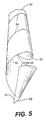
- an elongated rectangular sheet 50 of geotextile material is provided from a loom having a width corresponding to the width of a first end edge 51 and a second end edge (not shown in the Figs.) of sheet 50.
- elongated first side edge 53 is contiguous with first end edge 51.
- Elongated second side edge 52 is also contiguous with first end edge 51.
- a second end edge of sheet 50 is not visible in the view shown in Fig. 5, but is contiguous with first and second side edges 53, 52, respectively.
- the circumference "C" of the spiral tube to be formed by sheet 50 is the hypotenuse of the right triangle that includes the spiral length "L” as one leg and the width W of sheet 50 as the other leg of the triangle, wherein the angle ⁇ is the forming angle.
- the circumference of the spiral tube F (Fig. 6) is thus equal to pi (n) times the mean diameter "d" of the tube F.
- the length of sheet 50 will depend upon the desired size of the geotextile container in question and will require an elongated first side edge 53 of said length as well as an elongated second side edge 52 of said length.
- sheet 50 is furled in an helical shape such that first side edge 53 is overlapped on second side edge 52.
- a first line of stitching is applied to join first and second side edges 53, 52, respectively, in the manner described above in relation to the embodiment illustrated in Figs. 1-4.
- First line of stitching is disposed where respective first side edge 53 overlaps second side edge 52 to form a continuous seam having a flange 54 on one side and a finished line of joinder 57 between adjacent sides of sheet 50.
- a detail of a section of seam 57 would appear as flange 41 is depicted in Fig. 1A for example.
- the border portion of sheet 50 near first side edge 53 can be folded back onto itself to form a flap consisting of one or two thicknesses of the sheet of geotextile material.
- the border portion near second side edge 52 is similarly folded back onto itself to form a flap consisting of one or two thicknesses of the sheet of geotextile material.
- These two flaps are placed together to form a flange 54, which is shown in Fig. 6 for example.
- flange 54 consists of two or four thicknesses of the sheet 50 of geotextile material.
- flange 54 can be configured to form a butterfly seam as in Fig. 13A (four thicknesses), a butt seam as in Fig. 13B (two thicknesses) or a "J" seam as in Fig. 13C (four thicknesses).
- Flange 54 is sewn together by a first line of stitching, which desirably includes a plurality of double lock stitches.
- sheet 50 is spiraled to form a hollow tube F as shown in Fig. 6 for example.
- flange 54 extends in a helical line around the outside of hollow tube F.
- the open ends of tube F can be sewn closed in the same manner as described above for bag 20 shown in Fig. 4.
- this sack would be everted as shown for sack 48 in Fig. 2 for example. Then a port hole would be formed in the open end of the sack to permit closure of the open end by the formation of a multi-layer, flanged seam as described above in connection with the manufacturing steps schematically shown in Fig. 3.
- the resulting bag would have all of the flanges of the helical seam and the end seams disposed in the inner cavity of the bag so that upon being filled with the fill material, the flanges of the seams would be pressed against the side of the interior surface of the bag such as shown in Fig. 13 for example.
- this helical seam further strengthens the container by acting as might a reinforcing rope wound around the container along the length thereof. In the case of the present invention, such rope consists of either two or four thicknesses of geotextile material, depending on the type of seam.
- a geotextile container composed of at least one geotextile bag nested inside another geotextile bag such that the container includes a liner disposed therein.
- the container will have an outer layer of geotextile material and an inner layer of geotextile material conforming to the shape of the outer layer.
- liner inner layer
- furled and sewn tube F with the helical flange 54 and opposite helical joinder line 57 can be disposed upon a sheet 60 of geotextile fabric as shown in Fig. 7 for example.
- Sheet 60 has a width that is comparable to the circumference of tube F and a length that is comparable to the length of tube F.
- one or more sheets of geotextile material can be joined together with longitudinally extending seams in a manner described above and shown in Figs. 1 and 2 for example in order to build up to a sheet 60 of the desired width.
- a double-layer tube 66 is formed, as shown from an end plan view in Fig. 8.
- one open end of double-layer tube 66 is sewn closed.
- the end edges of the geotextile tube F which is the inner tube nesting in the geotextile tube 65 in the view shown in Fig. 8 are joined together by a multi-layer, flanged seam.
- a multi-layer, flanged seam such as shown in Figs. 13A, 13B, or 13C.
- the end edges of the geotextile fabric tube 65 which is the outer tube in the view shown in Fig. 8, are similarly joined together by a multi-layer, flanged seam as described above.
- geotextile tube 65 and geotextile tube F are desirably tacked together by stitching 63 located in several places down the lengths of and around the circumferences of the double-layer tube 66.
- the closed ends of the two tubes are desirably tacked to one another.
- Double-layer sack 67 has a first sack wall (or layer) 68 formed of geotextile material surrounding a second sack wall (or layer) 69 formed of geotextile material.
- double-layer sack 67 is everted so that the sack's second wall 69 becomes disposed outside of the sack's first wall 68 composed of geotextile material. This eversion is accomplished by grabbing the closed end of sack 67 from inside the sack 67 and pulling the closed end into the inner cavity 59 of sack 67 as shown schematically in Fig. 9 for example.
- Everted double-layer sack 70 has a closed end Y and an open end Z.
- the sewn flanges of each wall or layer 68, 69 are disposed to point toward the central longitudinal axis 58 of everted double-layer sack 70.
- the smooth or finished helical joinder line 57 of layer 69 is disposed outside sack 70.
- At least one port hole 72 is cut through both layers 68, 69 of everted double-layer sack 70 near the open end Z of everted sack 70. Additional port holes 72 can be provided in the double-layer everted sack 70. Desirably, the two layers 68, 69 of everted sack 70 are joined together around the edges of the aligned port holes 72 in the two layers.
- the unclosed ends of the two layers of everted double-layer sack 70 can be sewn closed in the same manner as shown in Fig. 3 for example.
- the free end edges of the inner layer 68 of geotextile material are pulled through a port hole 72 disposed closest to the open end Z of the everted double-layer sack 70. Once these free end edges of the geotextile layer 68 are outside sack 70, they are sewn closed by the formation of a sewn flange 64 that faces inside sack 70.
- the free end edges of the outer geotextile layer 69 are pulled through the same port hole 72 disposed closest to the open end Z of the everted double-layer sack 70, and similarly are sewn closed as a sewn flange 54 is formed to face inside sack 70.
- Geotextile container 80 is composed of an inner liner or layer 68 of geotextile material having elongated longitudinal seams with joinder lines 71 facing outside inner layer 68.
- Container 80 also includes and an outer bag or layer 69 formed of geotextile material and having a spiral, i.e., helically extending, seam with joinder line 57 facing outside container 80.
- a tubular chimney 73 formed of geotextile material for example, can be attached by stitching 74 to the container 80 around each port hole 72.
- Fig. 12 for example, can be attached by stitching 74 to the container 80 around each port hole 72.
- the longitudinal seams of the inner liner 68 are oriented substantially transverse to the helical seams of the outer layer 69. It is believed that this relative orientation of seams between the two layers of container 80, combines to provide yet additional strength is provided to the overall container 80. This additional strength is believed to enable container 80 to better withstand the outwardly directed forces resulting from the fill material 18 that eventually becomes disposed in the inner cavity of the container 18 when in use as shown in Figs. 11B and 11C.
- Fig. 15 illustrates a partial section of yet another embodiment of the container .
- a geotextile container 90 has at least two layers of geotextile material, a first layer being nested inside a second layer. However, each of the layers has a helical seam having a pitch that is out of phase with the other layer's helical seam.
- an inner layer 91 of geotextile material is shown in dashed line and has a first helical seam 92 that corkscrews in one direction with a first pitch.
- An outer layer 93 of geotextile material surrounds the inner layer 91 and has a second helical seam 94 that corkscrews in a second direction that is the opposite of the direction in which the first helical seam 92 of the inner layer 91 corkscrews.
- the one helical seam 92 is generally normal to the other helical seam 94 and thus intersects the other helical seam 94 as each seam 92, 94 winds around its respective layer 91, 93 of geotextile material.
- the pitch of the first helical seam 92 is generally out of phase with the pitch of the second helical seam 94.
- the two helical seams 92, 94 further strengthen the container 90 by acting as might two oppositely wound reinforcing ropes wrapped around the container along the length thereof in opposite directions.
- Each helical seam 92, 94 resists stresses in a different region of the container 90 so that the combination of the two seams provides a stronger overall container.
- inner cavity 81 of geotextile container 80 can be inflated by pumping water into same via one or more chimneys 73 and port holes 72 associated therewith and located at the top of the container 80.
- fill material is introduced into the inner cavity 81 of container 80 via one or more chimneys 73 and port holes 72 associated therewith and located at the top of the geotextile container 80.
- the inner liner 68 can be formed of material that is non-permeable to water.
- each of the port holes 72 is closed off in any conventional manner.
- tie-offs 79 are used to collapse the chimneys 73, but other more permanent closure mechanisms such as bolted plates can be used to bolt each port hole 72 closed.
- inner layer 68 can be formed of water permeable geotextile fabric.
- water becomes expelled through the pores in the inner layer 68 and outer layer 69 rather than through holes 72 and associated chimneys 73 that are not being used for pumping the fill material into the inner cavity 81 of the geotextile container.
- Fig. 13 schematically illustrates what happens to each multi-layer seam when the container becomes filled with the fill material.
- the butterfly seam S depicted in Fig. 13 can be considered a seam in the sheet of geotextile material that forms the outer layer 69 of a double-layer container 80 such as shown in Fig. 12 for example.
- Fig. 13 for example, when the inner cavity 81 of container 80 is filled with the fill material 18, an outwardly directed force will be imparted on the inside surface 82 of the inner layer 68 of the container 80.
- the weight of the fill material will apply pressure against each sewn flange 41 and its associated line of stitching disposed inside the inner cavity 81 of the container 80.
- the fill material flattens the flange against the inside surface 82 of the layer of geotextile material in which the flange is formed and thereby directs the outwardly directed stress forces from the weight of the fill material, in a perpendicular direction against the side of the fabric flange.
- flange 41 is flattened against the inside surface 85 of sheet 50 (which may be composed of a first sheet 21 and a second sheet 31 in some embodiments) and forms the outer layer 69 of container 80.
- the force of the fill material is believed to press together the opposed faces of fabric in the flange portion of the seam S rather than wedging or prying the flaps of fabric apart. It is believed that this pressure acts to reinforce the seam S by keeping the multiple thicknesses of material in the seam S pressed together. Instead of the internal pressure acting to pry the seam apart, the pressure appears to act to keep the seam from separating.
Landscapes
- General Engineering & Computer Science (AREA)
- Engineering & Computer Science (AREA)
- Structural Engineering (AREA)
- Ocean & Marine Engineering (AREA)
- Mechanical Engineering (AREA)
- Civil Engineering (AREA)
- Environmental & Geological Engineering (AREA)
- Bag Frames (AREA)
- Revetment (AREA)
- Cultivation Receptacles Or Flower-Pots, Or Pots For Seedlings (AREA)
- Lining Or Joining Of Plastics Or The Like (AREA)
- Manufacturing Of Tubular Articles Or Embedded Moulded Articles (AREA)
- Laminated Bodies (AREA)
- Emergency Lowering Means (AREA)
Claims (19)
- Ein verlängerter geotextile Behälter (20) vom Typ für Beibehaltenfüllenmaterial (18) und in einem Körper des Wassers benutzt zu werden, wie zum Beispiel eine Bucht oder ein Fluß, Steuerung der Erosion zu erleichtern. Und hat gesagt, daß Behälter Seiten entgegengesetzt war, und entgegengesetzte Enden, der Behälter (20) definierend eine innere Höhlung (16) zuzulassen, daß das Füllenmaterial darin enthalten wird, hat gesagt, daß Behälter (20) einschließend:Ein verlängertes zuerst Blatt (21) von künstlichem geotextile Material, hat das eine verlängerte zuerst Seitenkante (23) und ein verlängertes zuerst beendet Kante gesagt zuerst beendet Kante ist aneinandergrenzend mit zuerst Seitenkante (23) gesagt hat, hat zuerst gesagt, daß Blatt (21) weiter einen ersten Rand definierend, den nahes Gebiet zuerst Seitenkante (23) gesagt hat;Ein verlängertes zweites Blatt (31) von künstlichem geotextile Material, hat das eine verlängerte zuerst Seitenkante (33) und ein verlängertes zuerst Kante beendet, hat zuerst beendet Kante gesagt, hat gesagt, daß zuerst Endkante von hat gesagt, daß zweites Blatt (31) ist aneinandergrenzend mit hat gesagt zuerst Seitenkante (33) von zweites Blatt (31) gesagt hat, daß zweites Blatt (31) weiter einen zweiten Rand definierend, den nahes Gebiet zuerst Seitenkante (33) von gesagt hat, hat zweites Blatt (31); charakterisiert in gesagt hat gesagtDasHat gesagt, daß zweites Blatt (31) verfügt zu werden in bezug auf hat gesagt zuerst Blatt (21) in einer Position solch daß zuerst Seitenkanten (23,33) gewöhnlich sind ausgerichtet gesagt hat, und ist zuerst, daß Randgebiet entgegensetzt, zweites Randgebiet gesagt hat gesagt:Ein Mittel des Anschließens hat gesagt, daß erste und zweite Blätter entlang, daß entgegengesetzte zuerst und zweitens Rändergebiete gesagt hat, wenigstens Teil von einem Saum zu bilden;Worin hat gesagt, daß Teil von gesagt hat, daß Saum, der von zusammengesetzt worden ist, gesagt hat, daß erste und zweite Rändergebiete innerhalb der inneren Höhlung (16) vom Behälter (20) wobei eine äußerlich strahlenförmig geleitete Kraft verfügt werden, die auf dem Behälter (20) durch das Füllenmaterial erteilt worden ist, wird gegen hat gesagt geleitet werden, daß Teil von gesagt hat, daß Saum, der von zusammengesetzt worden ist, erste und zweite Rändergebiete gesagt hat.
- Ein Behälter (20), als in Anspruch 1 darlegt, worin:Hat gesagt, daß das Anschließen von Mittel eine erste Linie des Nähens (40) miteinschließt, schließend hat gesagt erste und zweite Blätter (21,31) in hat gesagt an, daß jeweiligen zuerst und zweitens Rand nahe Gebiete haben gesagt jeweiligen zuerst Seitenkanten (23,33) von erste und zweite Blätter (21,31), gesagt hat
- Ein Behälter (20), als in Anspruch 1 darlegt, oder beansprucht 2, hat worin gesagt, daß angeschlossene Rändergebiete Klaps von einem Kolbensaum bilden.
- Ein verlängerter geotextile Behälter (20,80,90) vom Typ für Beibehaltenfüllenmaterial (18) und in einem Körper des Wassers benutzt zu werden, wie zum Beispiel eine Bucht oder Fluß, Steuerung der Erosion zu erleichtern, haben gesagt, daß Behälter war entgegengesetzt Seiten und entgegengesetzte Enden, der Behälter (20,80,90) eine innere Höhlung (16) definierend, zuzulassen, daß das Füllenmaterial Behälter darin, ist, der charakterisiert wird, indem der Behälter einschließt:Ein verlängertes Blatt (50) von künstlichem geotextile Material, den ein erstes wird verlängert das Kante (51) beendet, hat zuerst gesagt, daß verlängert beendet Kante (51) ist aneinandergrenzend mit zuerst verlängerte Seitenkante (53) gesagt hat;Hat gesagt, daß Blatt (50) ist furled um sich in einer spiralenförmigen Gestalt solch daß hat gesagt zuerst, daß Seitenkante (53) ist überlappt auf zweite Seitenkante (52) gesagt hat, und siad zuerst Blatt (50) bildet ein hohles Rohr (F);Ein Mittel des Anschließens hat gesagt, daß erste und zweite Seitenkanten (53,52), einen ersten spiralenförmigen Saum (57.94) zu bilden, die um siad hohles Rohr (F) ausdehnen, und worin siad schließend Mittel inlcudes eine erste Linie von Nähen an und hat worin gesagt, daß hohles Rohr (F) everted ist, damit zuerst gesagt hat, daß Linie des Nähens hinein verfügt ist, hohles Rohr (F) hat gesagt.
- Ein Behälter (20,80,90), als in Anspruch 4 darlegt, hat worin zuerst Linie des Nähens vollständig ist verfügt innerhalb hat gesagt hohles Rohr (F) gesagt.
- Ein Behälter (20,80,90), als in Anspruch 4 darlegt, oder beansprucht 5, hat worin gesagt, daß Blatt (50) ein Hafenloch (E) verfügt nahe ein Ende vom Behälter (20,80,90) definiert.
- Ein Behälter (20,80,90), als in irgendein von Ansprüche 4-6 darlegt, hat worin gesagt, daß hohles Rohr (F) Enden (V), die genäht sind, haben geschlossen entgegengesetzt hat, die entgegengesetzten Enden (B,D) vom Behälter (20,80,90) zu bilden.
- Ein Behälter (20,80,90), als in irgendein von Ansprüche 4-7 darlegt, schließend weiter eine Buchse (68.91) hat verfügt innerhalb der inneren Höhlung (16) vom Behälter (20,80,90 ein) und Haben einer Außenoberfläche, die nach gegenübersteht, hat gesagt, daß zuerst spiralenförmiger Saum (57,94), daß Buchse gesagt hat, gestaltet zu werden, der Gestalt von der inneren Höhlung (16) vom Behälter (20,80,90) zu entsprechen.
- Ein Behälter (20,80,90), als in Anspruch 8 darlegt, hat worin gesagt, daß Buchse (68) wenigstens auf zweitem Saum (71) das miteinschließt, dehnt entlang hat gesagt Buchse (68) in gewöhnlich gerade axialer Richtung in einer Weise die gewöhnlich ist horizontal zu hat gesagt zuerst spiralenförmigem Saum (57) aus.
- Ein Behälter (90), als in Anspruch 8 darlegt, hat worin gesagt, daß Buchse (91) einen zweiten spiralenförmigen Saum (92) das miteinschließt, dehnt um hat gesagt Buchse (91) aus und hat worin gesagt, daß zuerst spiralenförmiger Saum (94) einen ersten Wurf hat, und hat gesagt, daß zweiter spiralenförmigen Saum (92) hat einen zweiten Wurf aus Phase mit zuerst Wurf gesagt hat.
- Ein Behälter (20,80,90), als in irgendein von Ansprüche 4-10 darlegt, hat hierin gesagt, daß erste und zweite Seitenkanten zu bilden einen Schmetterlingsaum gefaltet sind, und hat worin gesagt, daß das Anschließen von Mittel eine erste Linie des Nähens in der Form von einer Mehrheit die Stiche von doppeltem Schloß miteinschließt.
- Eine Methode, einen verlängerten geotextile Behälter (20,80,90) zu machen, in einem Körper des Wassers benutzt zu werden, wie zum Beispiel eine Bucht oder ein Fluß, Steuerung der Erosion zu erleichtern, der Behälter war Seiten entgegengesetzt und hat Enden entgegengesetzt und ist vom Typ, den einen verlängerten zuerst Saum hat, der in wenigstens einer Seite verfügt wird, gewöhnlich axial entlang der Länge vom Behälter (20) auszudehnen, weiter wenigstens einen zweiten Saum gewesen hatVerfügt in wenigstens auf Ende auf dem Behälter (20) den den dem Typ hat eine innere Höhlung (16) für Enthaltenfüllenmaterial sagte, daß Methode die Schritte von einschließend:Versorgen wenigstens zwei verlängerte Blätter (21.31) von künstlichem geotextile Material, worin hat jedes gesagt, daß Blatt eine erste verlängerte Seitenkante (23.33) und ein erstes hat, das verlängert wird, beendet Kante, die aneinandergrenzend mit ist, hat gesagt zuerst verlängerte Seitenkante, und worin jedes weitere Blatt läßt eine Sekunde verlängern Seite schieben sich aneinandergrenzend mit hat gesagt zuerst, daß verlängert Kante beendet, und hat gewöhnlich gegenüber zuerst verlängerte Seitenkante verfügt hat gesagt, und worin jedes weitere Blatt hat einZweit beendet schieben sich aneinandergrenzend mit hat gesagt, daß erste und zweite verlängerte Seitenkanten und hat verfügt gewöhnlich gegenüber hat gesagt zuerst, daß verlängert Kanten beendet; hat gesagt, daß Methode, durch charakterisiert zu werdenVerfügen ein erstes, das Ein von gesagt hat, daß künstlichen Blättern in bezug auf eine Sekunde Ein von hat gesagt, daß künstliche Blätter solch daß zuerst Seitenkanten (23.33) gewöhnlich sind ausgerichtet gesagt hat, und ist Blätter (21,31) berühren Ein gesagt, den ein anderer entlang wenigstens eines Rands nahes Gebiet zuerst Seite Kanten (23,33 gesagt hat);Verwenden eine erste Linie des Nähens (40) die das anschließt erste und zweite Blätter (21,31) gesagt haben, zuerst daß Linie des Nähens (40), in verfügt zu werden, gesagt haben gesagt, daß Rand nahes Gebiet jeweiligen zuerst Seitenkanten gesagt hat, (hat 23.33) von erste und zweite Blätter (21,31) gesagt;Verwenden eine zweite Linie anschließt von das nähend, hat gesagt, daß erste und zweite nahe Blätter gesagt haben, daß jeweilige zuerst Endkanten von erste und zweite Blätter gesagt hat;Anschließen zusammen genügende Blätter, einen verlängerten röhrenförmigen Sack (48) zu bilden, der wird geschlossen an einem ersten Ende (B) von hat gesagt Sack (48) gebildet durch hat gesagt angeschlossen zuerst Kanten beendet, haben Linien gesagt, daß des Nähens, der außerhalb verfügt worden ist, Sack (48), und hat gesagt gesagt hat, daß zweite Endkanten, die eine Öffnung an einem zweiten definieren, beenden (D) von hat gesagt Sack (48), und dann drehend Sack (48) hinein aus gesagt hat, damit Linien von gesagt hatNähen wird Verfügt innerhalb hat gesagt, daß Sack (48) wobei eine äußerlich direkte Kraft, die auf erteilt worden ist, hat gesagt Sack (48) durch das Füllenmaterial wird geleitet werden gegen Linien des Nähens gesagt hat.
- Eine Methode als Satz fort in Anspruch 12, worin bevor Verwenden zuerst Linie des Nähens (40) gesagt hat, hat zuerst Seitenkanten (23.33) von hat gesagt gesagt, daß erste und zweite Blätter (21.31) sind gefaltet hinter gegen jeweilig zuerst und zweite Blätter gesagt hat, eine Mehrfachschicht, geflanschten Saum, zu bilden, und hat zuerst gesagt, daß Linie des Nähens (40) eine Mehrheit die Stiche von doppeltem Schloß miteinschließt.
- Eine Methode, während Satz fort in Anspruch 12 oder 13 beansprucht, die weiter die Schritte von einschließen:Bildung hat ein Topfloch (E) nahe gesagt, daß Öffnung in gesagt hat, daß zweit beendet (D) von Sack (48) gesagt hat;Ziehen hat gesagt, daß zweit Kanten an hat gesagt beendet, daß zweit beendet (D) von hat gesagt Sack (48) durch hat gesagt dem Hafenloch (E) außerhalb Sack (48) gesagt hat;Verwenden eine dritte Linie nähend von das, hat gesagt, daß zweit Kanten beendet, zu schließen daß zweit beendet (D) von Sack (48) gesagt hat; und anschließt hat gesagtStoßen hat gesagt, daß zweit beendet Kanten mit hat gesagt dritte Linie des Nähens der hinter ist durch hat gesagt Hafenloch (E) ins innerhalb, daß Sack (48) gesagt hat, die innere Höhlung (16) vom Sack wobei eine äußerliche Kraft zu bilden, ist erteilt worden die auf den Behälter (20) durch das Füllenmaterial (18) wird gegen hat gesagt dntte Linie des Nähens geleitet werden.
- Eine Methode, einen verlängerten geotextile Behälter (20) zu machen, in einem Körper des Wassers benutzt zu werden, wie zum Beispiel eine Ducht oder ein Fluß, Steuerung von Erosion zu erleichtern, und, der vom Typ ist, den eine innere Höhlung (16) für Enthaltenfüllenmatetial (18) hat, hat gesagt, daß Methode, durch Einschließen der Schritte von charakterisiert zu werden:Versorgen ein verlängertes Blatt (50) von künstlichem geotextile Material, hat gesagt, daß Blatt (50) eine verlängerte zuerst Seitenkante (53) hat, und eine ersten Endkanten (51) das ist aneinandergrenzend mit hat gesagt zuerst Seitenkante (53), hat gesagt, daß Blatt (50) weiter hat eine verlängerte Sekunde Seite Kante (52) aneinandergrenzend mit hat gesagt zuerst Kante (51) beendet, und hat gewöhnlich gegenüber zuerst Seitenkante (53) verfügt hat gesagt, hat Blatt (50) noch weiter ein zweites Kante gesagt lassend been den Aneinandergrenzend mit hat gesagt, daß erste und zweite verlängerte Seitenkanten (53.52) und hat verfügt gewöhnlich gegenüber hat gesagt zuerst Kante (51) beendet;Furling hat Blatt (50) in einer spiralenförmigen Gestalt solch, daß hat gesagt zuerst, daß Seitenkante (53) ist überlappt auf, daß zweite Seitenkante (52) gesagt hat, gesagt und hat Blätternformen ein hohles Rohr (56); und gesagtAnschließen hat gesagt, daß erste und zweite Seitenkanten (53.52), wo haben gesagt jeweilige zuerst Seitenkante (53) überlappt, hat gesagt, daß zweite Seitenkante (52), einem ersten spiralenförmigen Saum (57) das zu bilden, schließt einen Flansch (54) das ausdehnt in einer spiralenförmigen Linie um hat gesagt hohlem Rohr (F), mitein und hat worin gesagt, daß hohles Rohr (F) everted ist, damit gesagt hat, daß Flansch (54) wird verfügt innerhalb hohles Rohr (F) gesagt hat.
- Eine Methode als Satz fort in Anspruch 5, worin bevor Anschließen erster und zweiter Seite Kanten (53,52) gesagt hat, hat gesagt, daß erste und zweite Seitenkanten (53.52) werden gefaltet von einer ersten Linie hinter gegen, daß Blatt (50) gesagt hat, eine Mehrfachschicht, geflanschten Saum, und zu bilden, hat worin gesagt, daß erste und zweite Seitenkanten (53.52) angeschlossen werden nähend von das eine Mehrheit die Stiche von doppeltem Schloß miteinschließt.
- Eine Methode als Satz fort in Anspruch 16, schließend weiter die Schritte von ein:Abdichten ein erstes Ende von hat gesagt, daß hohles Rohr (F) nah hat gesagt zuerst beendet Kante (51) von, daß Blatt gesagt hat, einen Sack (48) zu bilden, definierend ein abgedichtetes zuerst beendet (B), eine innere Höhlung (16), und eine unclosed Sekunde beendet (D) verfügten gewöhnlich gegenüber hat gesagt abgedichtet zuerst beendet (B) und nah hat gesagt, daß zweite Endkante von Blatt gesagt hat; undEverting hat gesagt, daß Sack (48), damit zuerst gesagt hat, daß Linie des Nähens wird verfügt innerhalb innere Höhlung (16) gesagt hat.
- Eine Methode als Satz fort in irgendeinem von Ansprüche 15-17, schließend weiter die Schritte von ein:Bildung ein Hafenloch (72) in hat gesagt, daß Blatt (50) nah gesagt hat, daß unclosed beendet (D) von Sack (48) gesagt hat;Ziehen hat gesagt, daß zweite Endkante von hat gesagt Blatt (50) durch hat gesagt dem Hafenloch (72) außerhalb Sack (48) gesagt hat; undStoßen hat gesagt, daß zweit beendet Kante mit dritte Linie des Nähens gesagt hat, der hinter ist durch hat Hafenloch (72) in hat gesagt innere Höhlung (16) vom Behälter (20) wobei eine äußerliche Kraft ist erteilt worden die auf dem Behälter (2) durch das Füllenmaterial (18) wird geleitet werden gegen hat gesagt dritte Linie des Nähens gesagt.
- Eine Methode als Satz fort in irgendeinem von Ansprüche 15-18, schließend weiter die Schritte von ein:Bildung eine äußere Schicht von geotextile Material Umgeben gesagt, daß hohles Rohr (F) und wenigstens eine zweite Linie des Nähens hat, der in verfügt worden ist, hat äußere Schicht gesagt;Abdichten ein erstes Ende von hat gesagt, daß hohles Rohr (F) nah hat gesagt zuerst beendet Kante (51) von, daß Blatt (50) gesagt hat, einen ersten Sack (48) zu bilden, definierend ein abgedichtetes zuerst beendet (B) und eine unclosed Sekunde beendet (D) verfügt gewöhnlich gegenüber hat gesagt abgedichtet zuerst beendet und nah hat gesagt, daß zweite Endkante von Blatt gesagt hat;Abdichten das ein Ende von hat gesagt, daß äußere nahe Schicht hat gesagt, daß abgedichteten zuerst Ende von zuerst, daß Sack (48) gesagt hat, einen zweiten Sack zu bilden, den ein definiert, hat ein Ende und eine unclosed Sekunde beenden verfügt gewöhnlich gegenüber hat gesagt hat abgedichtet ein Ende abgedichtet; undEverting hat zuerst gesagt, daß Sack (48) und hat gesagt, daß zweiter Sack damit hat gesagt, daß zuerst spiralenförmiger Saum (57) wird verfügt zwischen zuerst, daß Sack (48) gesagt hat, und hat gesagt, daß zweiter Sack und hat gesagt, daß zweite Linie des Nähens wird verfügt innerhalb einer inneren Höhlung (16) von zweiten Sack gesagt hat.
Applications Claiming Priority (3)
| Application Number | Priority Date | Filing Date | Title |
|---|---|---|---|
| US08/870,525 US5902070A (en) | 1997-06-06 | 1997-06-06 | Geotextile container and method of producing same |
| US870525 | 1997-06-06 | ||
| PCT/US1998/011002 WO1998055703A1 (en) | 1997-06-06 | 1998-05-29 | Improved geotextile container and method of producing same |
Publications (3)
| Publication Number | Publication Date |
|---|---|
| EP0986677A1 EP0986677A1 (de) | 2000-03-22 |
| EP0986677A4 EP0986677A4 (de) | 2002-04-10 |
| EP0986677B1 true EP0986677B1 (de) | 2004-08-04 |
Family
ID=25355563
Family Applications (1)
| Application Number | Title | Priority Date | Filing Date |
|---|---|---|---|
| EP98926131A Expired - Lifetime EP0986677B1 (de) | 1997-06-06 | 1998-05-29 | Verbesserter geotextilbehälter und sein produktionsverfahren |
Country Status (7)
| Country | Link |
|---|---|
| US (2) | US5902070A (de) |
| EP (1) | EP0986677B1 (de) |
| AT (1) | ATE272751T1 (de) |
| AU (1) | AU742307B2 (de) |
| CA (1) | CA2293505C (de) |
| DE (1) | DE69825442T2 (de) |
| WO (1) | WO1998055703A1 (de) |
Families Citing this family (56)
| Publication number | Priority date | Publication date | Assignee | Title |
|---|---|---|---|---|
| NL1002277C2 (nl) * | 1996-02-08 | 1997-08-11 | Nicolon Nv | Langwerpige flexibele houder. |
| US6343696B1 (en) * | 1999-04-06 | 2002-02-05 | Mccormick Richard Lee | Protective container |
| US7357598B1 (en) | 1999-08-05 | 2008-04-15 | Bradley Industrial Textiles, Inc. | Apparatus and method for deploying geotextile tubes |
| US6296420B1 (en) * | 1999-08-09 | 2001-10-02 | Michael J. Garbiso | Fluid control bag assemblies and method of using the same |
| US6648507B2 (en) * | 2000-04-19 | 2003-11-18 | Gta Containers, Inc. | Collapsible storage tank for liquids |
| ES2271067T3 (es) * | 2000-08-29 | 2007-04-16 | Artificial Surf Reefs Limited | Procedimientyo de proteccion del litoral. |
| US6739274B2 (en) | 2001-04-11 | 2004-05-25 | Albany International Corp. | End portions for a flexible fluid containment vessel and a method of making the same |
| US6860218B2 (en) * | 2001-04-11 | 2005-03-01 | Albany International Corp. | Flexible fluid containment vessel |
| US6718896B2 (en) | 2001-10-30 | 2004-04-13 | Albany International Corp. | Fabric structure for a flexible fluid containment vessel |
| US7107921B2 (en) * | 2001-10-30 | 2006-09-19 | Albany International Corp. | End portion for a flexible fluid containment vessel and a method of making the same |
| US6832571B2 (en) | 2001-10-30 | 2004-12-21 | Albany International Corp. | Segment formed flexible fluid containment vessel |
| DE10311296A1 (de) * | 2002-03-28 | 2003-10-16 | Huesker Synthetic Gmbh | Spülbehälter aus Gewebe |
| US6623214B1 (en) * | 2002-05-02 | 2003-09-23 | Shiner Moseley & Associates, Inc. | Modification of geotextile tubes |
| DE10245350B4 (de) * | 2002-09-27 | 2006-06-29 | Marks, Thomas, Dipl.-Ing. | Zylindrische Hülle |
| AU2003300179A1 (en) * | 2003-01-02 | 2004-07-29 | Nicolon Corporation | Inlet port for a container made of geotextiles |
| US7775171B2 (en) * | 2003-01-21 | 2010-08-17 | Albany International Corp. | Flexible fluid containment vessel featuring a keel-like seam |
| US20070009327A1 (en) * | 2003-05-27 | 2007-01-11 | Sanguinetti Peter S | Sediment control device and system |
| US6905289B1 (en) * | 2003-05-27 | 2005-06-14 | Peter S. Sanguinetti | Sediment control device and system |
| US20060127182A1 (en) * | 2003-05-27 | 2006-06-15 | Sanguinetti Peter S | Sediment control device and system |
| CA2443480A1 (en) * | 2003-09-30 | 2005-03-30 | Syn-Tex Convertors Ltd. | A form for containing settable filler material during setting |
| US7303084B2 (en) * | 2004-01-27 | 2007-12-04 | Mcphillips Kevin | Compositions, devices, and methods for use in environmental remediation |
| FR2874246B1 (fr) * | 2004-08-12 | 2007-04-27 | Jean Charles Dalaine | Procede pour proteger un cable ou une conduite |
| WO2006028435A1 (en) * | 2004-09-03 | 2006-03-16 | Bradley Industrial Textiles, Inc. | Geotextile multi-tube assemblage |
| WO2006027559A1 (en) * | 2004-09-10 | 2006-03-16 | Qinetiq Limited | Fascines |
| US20060102565A1 (en) * | 2004-11-12 | 2006-05-18 | Alford Paul W | System and method for dewatering sludge, slurry or sediment |
| US7832959B1 (en) | 2005-04-18 | 2010-11-16 | Bean Stuyvesant, L.L.C. | Method of restoration of a highly saline lake |
| US7097390B1 (en) * | 2005-06-16 | 2006-08-29 | Mega, Inc. | Fine-grained fill reinforcing apparatus and method |
| US8088117B2 (en) * | 2005-10-25 | 2012-01-03 | Nicolon Corporation | Fill port for a flexible container for relieving or distributing stresses at the fill port |
| US7449105B2 (en) * | 2006-07-19 | 2008-11-11 | Denny Hastings Flp 14 | Water filtration and erosion control system |
| US7891914B2 (en) * | 2007-11-15 | 2011-02-22 | Flint Industries, Inc. | Geotextile tube |
| US7820054B2 (en) * | 2008-01-14 | 2010-10-26 | Denny Hastings Flp 14 | Method for dewatering slurry from construction sites |
| US8777523B2 (en) * | 2008-02-15 | 2014-07-15 | Nicolon Corporation | Geotextile tube with flat ends |
| KR101028742B1 (ko) * | 2008-04-16 | 2011-04-14 | 전양진 | 지오튜브 제조방법 및 지오튜브 |
| GB0811853D0 (en) * | 2008-06-27 | 2008-07-30 | Aldridge Natalie | Equipment |
| RU2381137C1 (ru) * | 2008-08-04 | 2010-02-10 | Юрий Алексеевич Берков | Средство для транспортировки жидких грузов |
| KR101136473B1 (ko) * | 2009-08-05 | 2012-04-19 | 주식회사 새날테크-텍스 | 봉제선이 없는 지오텍스타일 튜브 및 그 제조방법 |
| KR101070355B1 (ko) | 2009-09-10 | 2011-10-05 | 오성훈 | 지오텍스타일튜브의 봉합연결구조 |
| JP2013506098A (ja) * | 2009-09-23 | 2013-02-21 | レイモンド フレイジャー,スコット | 水中に圧縮流体エネルギを貯蔵するシステムおよび同システムを配置する方法 |
| JP5089711B2 (ja) * | 2010-01-12 | 2012-12-05 | 株式会社モンベル | 衣類及び衣類の製造方法 |
| TW201209247A (en) * | 2010-08-24 | 2012-03-01 | Gold Joint Ind Co Ltd | Geotextile tube with radial reinforcement |
| US9745713B2 (en) * | 2011-03-15 | 2017-08-29 | Board Of Supervisors Of Louisiana State University And Agricultural And Mechanical College | Device for coastal restoration |
| US9163373B2 (en) | 2011-08-25 | 2015-10-20 | Bradley Industrial Textiles, Inc. | Multi-ribbed geotextile tubes and segments thereof |
| WO2013033435A1 (en) * | 2011-08-30 | 2013-03-07 | Nike International Ltd. | Woven textile organizer for bags |
| NL2007821C2 (nl) * | 2011-11-21 | 2013-05-23 | Besekk B V | Werkwijze voor het ontwateren van grond met behulp van een filtratiemiddel. |
| US9663290B2 (en) * | 2011-12-01 | 2017-05-30 | Gta Containers, Inc. | Method of fabrication of collapsible storage tank |
| TWM443023U (en) * | 2012-05-29 | 2012-12-11 | Gold Joint Ind Co Ltd | Sea bottom deposit sand bag |
| US9982406B2 (en) | 2012-07-06 | 2018-05-29 | Bradley Industrial Textiles, Inc. | Geotextile tubes with porous internal shelves for inhibiting shear of solid fill material |
| FR2996406A1 (fr) * | 2012-10-08 | 2014-04-11 | Arielle Bony | Sac drainant amovible et reutilisable |
| USD722408S1 (en) * | 2012-12-05 | 2015-02-10 | Yoshinobu Nakai | Tool for picking up animal waste |
| US9845583B1 (en) * | 2016-08-18 | 2017-12-19 | Gold-Joint Industry Co., Ltd. | Geotextile tube |
| WO2018053088A1 (en) * | 2016-09-14 | 2018-03-22 | Tensar International Corporation | Marine and river protection system and method of supporting coastal structures |
| IT201600126498A1 (it) * | 2016-12-14 | 2018-06-14 | Maccaferri Off Spa | Sacco per la realizzazione di opere dell’ingegneria civile, procedimento per la sua fabbricazione, e per la realizzazione di un’opera mediante più sacchi di tale tipo |
| CN110106831A (zh) * | 2019-06-11 | 2019-08-09 | 汪磊 | 一种新型螺旋式土工管袋及其制备方法 |
| CA3116876C (en) * | 2020-04-29 | 2023-01-03 | Canadian National Railway Company | Device for dewatering and method of making same |
| WO2022155711A1 (en) * | 2021-01-25 | 2022-07-28 | Icon Advertising Pty Ltd | Building modules and techniques to make them |
| CN113047315A (zh) * | 2021-03-31 | 2021-06-29 | 上海交通大学 | 适用于膨胀土边坡的防滑防水土工编织袋及施工方法 |
Family Cites Families (23)
| Publication number | Priority date | Publication date | Assignee | Title |
|---|---|---|---|---|
| US490103A (en) * | 1893-01-17 | James ross collins | ||
| US781494A (en) * | 1904-02-27 | 1905-01-31 | Albert Strong Coltharp | Embankment protection. |
| US815255A (en) * | 1905-11-15 | 1906-03-13 | William G Bell | Bag or package. |
| US909423A (en) * | 1908-07-15 | 1909-01-12 | John C Keller | Shore-protector. |
| US1211853A (en) * | 1913-08-01 | 1917-01-09 | Gurry E Huggins | Bag. |
| US1206417A (en) * | 1915-09-10 | 1916-11-28 | Harry K Cunkle | Reversible mailing-bag. |
| US1642204A (en) * | 1926-09-11 | 1927-09-13 | Union Asbestos & Rubber Co | Heat-insulating tape |
| US2588695A (en) * | 1948-12-04 | 1952-03-11 | Bemis Bro Bag Co | Labeled open-mesh bag |
| US3373568A (en) * | 1965-09-13 | 1968-03-19 | Lloyd Hornbostel Jr. | System for reclamation of land |
| US3340919A (en) * | 1965-12-15 | 1967-09-12 | Johnson & Johnson | Bag |
| GB1208205A (en) * | 1967-10-13 | 1970-10-07 | Toray Industries | Textile lining structure for use as revetment |
| DE1784360A1 (de) * | 1968-07-30 | 1971-10-07 | Hoechst Ag | Gewebematte |
| US3957098A (en) * | 1972-06-26 | 1976-05-18 | George Hepworth | Erosion control bag |
| US3886751A (en) * | 1973-11-12 | 1975-06-03 | Jimenez Labora Mauricio Porraz | Aquatic construction module and method of forming thereof |
| US4275493A (en) * | 1975-08-20 | 1981-06-30 | Edwin Matovich | Method for making a fabric reactor tube |
| US4690585A (en) * | 1985-01-17 | 1987-09-01 | Holmberg Dick L | Erosion control foundation mat and method |
| NL8602859A (nl) * | 1986-11-11 | 1988-06-01 | Nicolon Nv | Werkwijze voor het vormen en op een gekozen plaats deponeren van een lichaam. |
| NL8602875A (nl) * | 1986-11-12 | 1988-06-01 | Nicolon Nv | Werkwijze voor het vormen van een lichaam, bijvoorbeeld een dijklichaam, een daarvoor bestemd buislichaam, alsmede een werkwijze voor het vervaardigen van een dergelijk buislichaam. |
| US4696244A (en) * | 1986-12-22 | 1987-09-29 | Doboy Packaging Machinery, Inc. | Thread chaining detector |
| US5098754A (en) * | 1990-05-29 | 1992-03-24 | Marilyn Horstmyer | Hay bag |
| US5492073A (en) * | 1994-06-14 | 1996-02-20 | Trw Vehicle Safety Systems Inc. | Inflatable vehicle occupant restraint including sewn panels |
| US5595458A (en) * | 1994-06-29 | 1997-01-21 | Grabhorn, Inc. | Biofilter bags for erosion control |
| US5505557A (en) * | 1994-11-22 | 1996-04-09 | Bradley Industrial Textiles, Inc. | Geotextile container |
-
1997
- 1997-06-06 US US08/870,525 patent/US5902070A/en not_active Expired - Lifetime
-
1998
- 1998-05-29 CA CA002293505A patent/CA2293505C/en not_active Expired - Fee Related
- 1998-05-29 DE DE69825442T patent/DE69825442T2/de not_active Expired - Fee Related
- 1998-05-29 WO PCT/US1998/011002 patent/WO1998055703A1/en not_active Ceased
- 1998-05-29 AT AT98926131T patent/ATE272751T1/de not_active IP Right Cessation
- 1998-05-29 AU AU78039/98A patent/AU742307B2/en not_active Ceased
- 1998-05-29 EP EP98926131A patent/EP0986677B1/de not_active Expired - Lifetime
- 1998-09-29 US US09/163,122 patent/US6056438A/en not_active Expired - Fee Related
Also Published As
| Publication number | Publication date |
|---|---|
| US6056438A (en) | 2000-05-02 |
| CA2293505C (en) | 2005-10-04 |
| AU7803998A (en) | 1998-12-21 |
| HK1026464A1 (en) | 2000-12-15 |
| US5902070A (en) | 1999-05-11 |
| CA2293505A1 (en) | 1998-12-10 |
| AU742307B2 (en) | 2001-12-20 |
| EP0986677A4 (de) | 2002-04-10 |
| ATE272751T1 (de) | 2004-08-15 |
| DE69825442T2 (de) | 2005-09-15 |
| EP0986677A1 (de) | 2000-03-22 |
| WO1998055703A1 (en) | 1998-12-10 |
| DE69825442D1 (de) | 2004-09-09 |
Similar Documents
| Publication | Publication Date | Title |
|---|---|---|
| EP0986677B1 (de) | Verbesserter geotextilbehälter und sein produktionsverfahren | |
| US4807299A (en) | Bulk containers | |
| US7891914B2 (en) | Geotextile tube | |
| KR100603506B1 (ko) | 유체 보관용 연질 용기 및 이의 제조 방법 | |
| AU771416B2 (en) | Apparatus and method for deploying geotextile tubes | |
| US6739274B2 (en) | End portions for a flexible fluid containment vessel and a method of making the same | |
| KR0163582B1 (ko) | 가요성 중급 벌크용기 | |
| US5865541A (en) | Bulk container liner and method | |
| EP0475703A1 (de) | Schüttgutbehälter | |
| US5505557A (en) | Geotextile container | |
| JP2005507814A (ja) | 可撓性流体格納容器のファブリック構造 | |
| CA2481709C (en) | Improved geotextile container and method of producing same | |
| EP0364059B1 (de) | Rohrkörper zum Herstellen von beispielsweise eines Deichkörpers und Verfahren zum Herstellen eines solchen Rohrkörpers | |
| HK1026464B (en) | Improved geotextile container and method of producing same | |
| TW202408809A (zh) | 用於運輸散裝液體的柔性貯罐及其製造方法 | |
| MXPA99011114A (en) | Improved geotextile container and method of producing same | |
| EP0311662A1 (de) | Flexibler behälter mit mehreren hebemitteln. | |
| EP1383677B1 (de) | Endabschnitte für einen flexiblen flüssigkeitsbehälter und verfahren zu dessen herstellung | |
| CN100554081C (zh) | 挠性流体密封外壳 | |
| AU2002307110A1 (en) | End portions for a flexible fluid containment vessel and a method of making the same | |
| JPH08239833A (ja) | 袋体付杭 | |
| JP3220309U (ja) | 耐圧土のう袋 | |
| EP0664259A1 (de) | Sackbehälter | |
| GB2133353A (en) | Flotation bags | |
| MXPA03009394A (es) | Prociones de extremo para una embarcacion flexible de contencion de fluido y metodo para hacer el mismo. |
Legal Events
| Date | Code | Title | Description |
|---|---|---|---|
| PUAI | Public reference made under article 153(3) epc to a published international application that has entered the european phase |
Free format text: ORIGINAL CODE: 0009012 |
|
| 17P | Request for examination filed |
Effective date: 19991217 |
|
| AK | Designated contracting states |
Kind code of ref document: A1 Designated state(s): AT BE CH DE DK ES FI FR GB GR IE IT LI LU MC NL PT SE |
|
| A4 | Supplementary search report drawn up and despatched |
Effective date: 20020227 |
|
| AK | Designated contracting states |
Kind code of ref document: A4 Designated state(s): AT BE CH DE DK ES FI FR GB GR IE IT LI LU MC NL PT SE |
|
| 17Q | First examination report despatched |
Effective date: 20020809 |
|
| GRAP | Despatch of communication of intention to grant a patent |
Free format text: ORIGINAL CODE: EPIDOSNIGR1 |
|
| RIC1 | Information provided on ipc code assigned before grant |
Ipc: 7E 02B 3/04 B Ipc: 7E 02B 3/12 A |
|
| GRAS | Grant fee paid |
Free format text: ORIGINAL CODE: EPIDOSNIGR3 |
|
| GRAA | (expected) grant |
Free format text: ORIGINAL CODE: 0009210 |
|
| AK | Designated contracting states |
Kind code of ref document: B1 Designated state(s): AT BE CH DE DK ES FI FR GB GR IE IT LI LU MC NL PT SE |
|
| PG25 | Lapsed in a contracting state [announced via postgrant information from national office to epo] |
Ref country code: NL Free format text: LAPSE BECAUSE OF FAILURE TO SUBMIT A TRANSLATION OF THE DESCRIPTION OR TO PAY THE FEE WITHIN THE PRESCRIBED TIME-LIMIT Effective date: 20040804 Ref country code: LI Free format text: LAPSE BECAUSE OF FAILURE TO SUBMIT A TRANSLATION OF THE DESCRIPTION OR TO PAY THE FEE WITHIN THE PRESCRIBED TIME-LIMIT Effective date: 20040804 Ref country code: IT Free format text: LAPSE BECAUSE OF FAILURE TO SUBMIT A TRANSLATION OF THE DESCRIPTION OR TO PAY THE FEE WITHIN THE PRE;WARNING: LAPSES OF ITALIAN PATENTS WITH EFFECTIVE DATE BEFORE 2007 MAY HAVE OCCURRED AT ANY TIME BEFORE 2007. THE CORRECT EFFECTIVE DATE MAY BE DIFFERENT FROM THE ONE RECORDED.SCRIBED TIME-LIMIT Effective date: 20040804 Ref country code: FI Free format text: LAPSE BECAUSE OF FAILURE TO SUBMIT A TRANSLATION OF THE DESCRIPTION OR TO PAY THE FEE WITHIN THE PRESCRIBED TIME-LIMIT Effective date: 20040804 Ref country code: CH Free format text: LAPSE BECAUSE OF FAILURE TO SUBMIT A TRANSLATION OF THE DESCRIPTION OR TO PAY THE FEE WITHIN THE PRESCRIBED TIME-LIMIT Effective date: 20040804 Ref country code: BE Free format text: LAPSE BECAUSE OF FAILURE TO SUBMIT A TRANSLATION OF THE DESCRIPTION OR TO PAY THE FEE WITHIN THE PRESCRIBED TIME-LIMIT Effective date: 20040804 Ref country code: AT Free format text: LAPSE BECAUSE OF FAILURE TO SUBMIT A TRANSLATION OF THE DESCRIPTION OR TO PAY THE FEE WITHIN THE PRESCRIBED TIME-LIMIT Effective date: 20040804 |
|
| REG | Reference to a national code |
Ref country code: GB Ref legal event code: FG4D |
|
| REG | Reference to a national code |
Ref country code: CH Ref legal event code: EP |
|
| REG | Reference to a national code |
Ref country code: IE Ref legal event code: FG4D |
|
| REF | Corresponds to: |
Ref document number: 69825442 Country of ref document: DE Date of ref document: 20040909 Kind code of ref document: P |
|
| PG25 | Lapsed in a contracting state [announced via postgrant information from national office to epo] |
Ref country code: SE Free format text: LAPSE BECAUSE OF FAILURE TO SUBMIT A TRANSLATION OF THE DESCRIPTION OR TO PAY THE FEE WITHIN THE PRESCRIBED TIME-LIMIT Effective date: 20041104 Ref country code: GR Free format text: LAPSE BECAUSE OF FAILURE TO SUBMIT A TRANSLATION OF THE DESCRIPTION OR TO PAY THE FEE WITHIN THE PRESCRIBED TIME-LIMIT Effective date: 20041104 Ref country code: DK Free format text: LAPSE BECAUSE OF FAILURE TO SUBMIT A TRANSLATION OF THE DESCRIPTION OR TO PAY THE FEE WITHIN THE PRESCRIBED TIME-LIMIT Effective date: 20041104 |
|
| PG25 | Lapsed in a contracting state [announced via postgrant information from national office to epo] |
Ref country code: ES Free format text: LAPSE BECAUSE OF FAILURE TO SUBMIT A TRANSLATION OF THE DESCRIPTION OR TO PAY THE FEE WITHIN THE PRESCRIBED TIME-LIMIT Effective date: 20041115 |
|
| REG | Reference to a national code |
Ref country code: HK Ref legal event code: GR Ref document number: 1026464 Country of ref document: HK |
|
| NLV1 | Nl: lapsed or annulled due to failure to fulfill the requirements of art. 29p and 29m of the patents act | ||
| REG | Reference to a national code |
Ref country code: CH Ref legal event code: PL |
|
| PG25 | Lapsed in a contracting state [announced via postgrant information from national office to epo] |
Ref country code: LU Free format text: LAPSE BECAUSE OF NON-PAYMENT OF DUE FEES Effective date: 20050529 Ref country code: GB Free format text: LAPSE BECAUSE OF NON-PAYMENT OF DUE FEES Effective date: 20050529 |
|
| PG25 | Lapsed in a contracting state [announced via postgrant information from national office to epo] |
Ref country code: IE Free format text: LAPSE BECAUSE OF NON-PAYMENT OF DUE FEES Effective date: 20050530 |
|
| PG25 | Lapsed in a contracting state [announced via postgrant information from national office to epo] |
Ref country code: MC Free format text: LAPSE BECAUSE OF NON-PAYMENT OF DUE FEES Effective date: 20050531 |
|
| PLBE | No opposition filed within time limit |
Free format text: ORIGINAL CODE: 0009261 |
|
| STAA | Information on the status of an ep patent application or granted ep patent |
Free format text: STATUS: NO OPPOSITION FILED WITHIN TIME LIMIT |
|
| ET | Fr: translation filed | ||
| 26N | No opposition filed |
Effective date: 20050506 |
|
| GBPC | Gb: european patent ceased through non-payment of renewal fee |
Effective date: 20050529 |
|
| REG | Reference to a national code |
Ref country code: IE Ref legal event code: MM4A |
|
| PG25 | Lapsed in a contracting state [announced via postgrant information from national office to epo] |
Ref country code: PT Free format text: LAPSE BECAUSE OF NON-PAYMENT OF DUE FEES Effective date: 20050104 |
|
| PGFP | Annual fee paid to national office [announced via postgrant information from national office to epo] |
Ref country code: DE Payment date: 20080530 Year of fee payment: 11 |
|
| REG | Reference to a national code |
Ref country code: FR Ref legal event code: ST Effective date: 20100129 |
|
| PG25 | Lapsed in a contracting state [announced via postgrant information from national office to epo] |
Ref country code: FR Free format text: LAPSE BECAUSE OF NON-PAYMENT OF DUE FEES Effective date: 20090602 |
|
| PGFP | Annual fee paid to national office [announced via postgrant information from national office to epo] |
Ref country code: FR Payment date: 20080424 Year of fee payment: 11 |
|
| PG25 | Lapsed in a contracting state [announced via postgrant information from national office to epo] |
Ref country code: DE Free format text: LAPSE BECAUSE OF NON-PAYMENT OF DUE FEES Effective date: 20091201 |