EP0985859A2 - Vorrichtung und Verfahren an mehrgängigen Schaltgetrieben - Google Patents
Vorrichtung und Verfahren an mehrgängigen Schaltgetrieben Download PDFInfo
- Publication number
- EP0985859A2 EP0985859A2 EP99117071A EP99117071A EP0985859A2 EP 0985859 A2 EP0985859 A2 EP 0985859A2 EP 99117071 A EP99117071 A EP 99117071A EP 99117071 A EP99117071 A EP 99117071A EP 0985859 A2 EP0985859 A2 EP 0985859A2
- Authority
- EP
- European Patent Office
- Prior art keywords
- switching
- control device
- spring
- control
- switching pin
- Prior art date
- Legal status (The legal status is an assumption and is not a legal conclusion. Google has not performed a legal analysis and makes no representation as to the accuracy of the status listed.)
- Granted
Links
- 238000000034 method Methods 0.000 title claims abstract description 12
- 230000005540 biological transmission Effects 0.000 claims abstract description 23
- 230000002706 hydrostatic effect Effects 0.000 claims description 9
- 230000000903 blocking effect Effects 0.000 claims description 7
- 230000007935 neutral effect Effects 0.000 claims description 5
- 230000009471 action Effects 0.000 claims description 3
- 230000008859 change Effects 0.000 description 13
- 241001124569 Lycaenidae Species 0.000 description 3
- 230000008901 benefit Effects 0.000 description 3
- 230000008878 coupling Effects 0.000 description 3
- 238000010168 coupling process Methods 0.000 description 3
- 238000005859 coupling reaction Methods 0.000 description 3
- 238000006073 displacement reaction Methods 0.000 description 3
- 230000000694 effects Effects 0.000 description 2
- 238000003306 harvesting Methods 0.000 description 2
- 238000009434 installation Methods 0.000 description 2
- 230000003213 activating effect Effects 0.000 description 1
- 230000004913 activation Effects 0.000 description 1
- 230000002411 adverse Effects 0.000 description 1
- 239000003795 chemical substances by application Substances 0.000 description 1
- 230000007547 defect Effects 0.000 description 1
- 239000004459 forage Substances 0.000 description 1
- 230000005021 gait Effects 0.000 description 1
- 238000004519 manufacturing process Methods 0.000 description 1
- 230000002093 peripheral effect Effects 0.000 description 1
- 238000003825 pressing Methods 0.000 description 1
- 230000002265 prevention Effects 0.000 description 1
- 230000008569 process Effects 0.000 description 1
- 230000003014 reinforcing effect Effects 0.000 description 1
- 230000000717 retained effect Effects 0.000 description 1
- 230000001360 synchronised effect Effects 0.000 description 1
Images


Classifications
-
- F—MECHANICAL ENGINEERING; LIGHTING; HEATING; WEAPONS; BLASTING
- F16—ENGINEERING ELEMENTS AND UNITS; GENERAL MEASURES FOR PRODUCING AND MAINTAINING EFFECTIVE FUNCTIONING OF MACHINES OR INSTALLATIONS; THERMAL INSULATION IN GENERAL
- F16H—GEARING
- F16H63/00—Control outputs from the control unit to change-speed- or reversing-gearings for conveying rotary motion or to other devices than the final output mechanism
- F16H63/02—Final output mechanisms therefor; Actuating means for the final output mechanisms
- F16H63/30—Constructional features of the final output mechanisms
- F16H63/34—Locking or disabling mechanisms
-
- F—MECHANICAL ENGINEERING; LIGHTING; HEATING; WEAPONS; BLASTING
- F16—ENGINEERING ELEMENTS AND UNITS; GENERAL MEASURES FOR PRODUCING AND MAINTAINING EFFECTIVE FUNCTIONING OF MACHINES OR INSTALLATIONS; THERMAL INSULATION IN GENERAL
- F16H—GEARING
- F16H61/00—Control functions within control units of change-speed- or reversing-gearings for conveying rotary motion ; Control of exclusively fluid gearing, friction gearing, gearings with endless flexible members or other particular types of gearing
- F16H61/16—Inhibiting or initiating shift during unfavourable conditions , e.g. preventing forward-reverse shift at high vehicle speed, preventing engine overspeed
-
- Y—GENERAL TAGGING OF NEW TECHNOLOGICAL DEVELOPMENTS; GENERAL TAGGING OF CROSS-SECTIONAL TECHNOLOGIES SPANNING OVER SEVERAL SECTIONS OF THE IPC; TECHNICAL SUBJECTS COVERED BY FORMER USPC CROSS-REFERENCE ART COLLECTIONS [XRACs] AND DIGESTS
- Y10—TECHNICAL SUBJECTS COVERED BY FORMER USPC
- Y10T—TECHNICAL SUBJECTS COVERED BY FORMER US CLASSIFICATION
- Y10T70/00—Locks
- Y10T70/50—Special application
- Y10T70/5889—For automotive vehicles
- Y10T70/5925—Transmission
-
- Y—GENERAL TAGGING OF NEW TECHNOLOGICAL DEVELOPMENTS; GENERAL TAGGING OF CROSS-SECTIONAL TECHNOLOGIES SPANNING OVER SEVERAL SECTIONS OF THE IPC; TECHNICAL SUBJECTS COVERED BY FORMER USPC CROSS-REFERENCE ART COLLECTIONS [XRACs] AND DIGESTS
- Y10—TECHNICAL SUBJECTS COVERED BY FORMER USPC
- Y10T—TECHNICAL SUBJECTS COVERED BY FORMER US CLASSIFICATION
- Y10T74/00—Machine element or mechanism
- Y10T74/19—Gearing
- Y10T74/19219—Interchangeably locked
- Y10T74/19251—Control mechanism
-
- Y—GENERAL TAGGING OF NEW TECHNOLOGICAL DEVELOPMENTS; GENERAL TAGGING OF CROSS-SECTIONAL TECHNOLOGIES SPANNING OVER SEVERAL SECTIONS OF THE IPC; TECHNICAL SUBJECTS COVERED BY FORMER USPC CROSS-REFERENCE ART COLLECTIONS [XRACs] AND DIGESTS
- Y10—TECHNICAL SUBJECTS COVERED BY FORMER USPC
- Y10T—TECHNICAL SUBJECTS COVERED BY FORMER US CLASSIFICATION
- Y10T74/00—Machine element or mechanism
- Y10T74/19—Gearing
- Y10T74/19219—Interchangeably locked
- Y10T74/19251—Control mechanism
- Y10T74/19256—Automatic
- Y10T74/1926—Speed responsive
Definitions
- the invention relates to a device and a method on a multi-speed manual transmission with at least one shift rod, each with a predetermined position at least one fixing element for fixing the shift rod can be acted upon.
- DE 22 23 553 A1 describes a generic device on a multi-course Gear known, in which a locking element is provided in addition to the fixing element is that the shift rod is locked in a predetermined position.
- the fact that the locking element acts on the shift rod at a right angle to the fixing element is a increased installation space required.
- the shift rod must be designed in this way be that the locking force applied by the locking element is exerted safely can be. In particular, if there are more than two shift rods known device relatively expensive.
- a gear lock for transmissions in which a shift rod of a locking sleeve with recesses arranged offset on the peripheral edge is surrounded. These depressions serve on the one hand to accommodate her a fixing element and on the other hand as a holder for a locking element.
- a disadvantage of the known gear lock is that by providing the locking element on the one hand and by an angle from 180 ° along the circumferential surface of the locking element offset locking element requires relatively large installation space.
- the invention is characterized in that a fixing element is operatively connected to an actuator such that the actuator by means of a control device is adjustable in at least two different positions relative to the fixing element.
- the advantage of the invention can be seen in particular in the fact that the control element with the Fixing element is coupled, the actuating element on the fixing element in the sense of a reinforcing force exerted to generate a holding force by the Fixing element is transferred to the shift rod.
- the basic idea of the invention is here that only the fixing element acts directly on the sound rod while the actuating element acts on the shift rod by coupling the fixing element. This allows space-saving a plurality of forces acting on the shift rod produce.
- the control element is in two Positions can be brought, wherein the fixing element, the shift rod in a first switching position with a fixing force and in a second holding position with a larger fixing force.
- This advantageously makes a two-stage application of force to the shift rod enables an unwanted switching operation in a holding position of the control element of the gearbox, due to possible load changes in the gearbox or due to moments that Movements of the vehicle act on the shift linkage, is effectively prevented.
- the switching position of the control element enables a gear change, the switching force is set such that the operator clicks the fixing element into place perceived gear.
- the gear change is preferably carried out in one torque-free state of the transmission, being in the shadow of the fixing element a constant shifting force is automatically exerted on the shift rod.
- the fixing element is operatively connected by a Spring, in the switching position of the control element, with a fixing force and in the holding position with a spring-loaded actuator with a larger fixing force. Regardless of the position of the control element, a predetermined force exerted on the shift rod.
- the actuating element is designed as a switching pin which by means of a control device by axial displacement from the first switching position in a two predetermined stop position can be brought.
- the switching pin is operated by means of a hydraulic Control device actuated.
- the control element is designed as a type of piston. That piston can be easily guided in a hole and also by inexpensive and known Seal the agent against the neighboring housing parts.
- the switching pin is a first spring and assigned a second spring, the springs in opposite directions to the Switch pin are arranged.
- This has the advantage of being in the holding position of the control element no application of hydraulic means is necessary. This represents a kind of intrinsic safety the device, so that in the event of a failure of the pressure medium supply a safe Holding the shift rod is ensured.
- the first spring has a first end on the fixing element abuts and with the other opposite end against a first stop of the Switch pin supports.
- the second spring is supported with a first end on a housing part and with an opposite end on a second stop of the switching pin.
- a connection between the springs by means of which a pressure medium can be fed into this area is so that the holding force applied by the second spring can be compensated.
- the switching pin When the switching pin is acted upon, it is in its switching position in the only the first spring acts on the fixing element. Is only advantageous during the brief switching, in the torque-free state of the transmission, the second spring force compensated. Exercises in the event of a defect or failure of the control device the second spring always a fixing force, so that an unwanted gait or unwanted gear changes are effectively prevented.
- a second spring can be dispensed with and the switching pin is designed as a simple piston become.
- the intrinsic safety of the device is adversely affected, since that Fixing or the control element in the event of failure of the control device only in the Switching position.
- the switching valve can be designed so that it is both connections of the in the non-switched state Device supplied with pressure medium at the same time and only one when switched Connects to the tank. There may also be several switching valves so that when there are several connections on the device, the connections can be applied independently. An equipment with different Pressure medium sources for the generation and supply of the connections with different Pressing is also conceivable.
- the short-circuit valve is therefore provided to connect to the control device and a control of the short-circuit valve to be carried out in connection with the control of the device according to the invention.
- the control of the switching pin can take place in such a way that the control device Switch pin on both connections simultaneously with the same or different pressure provided. Furthermore, it is possible by the control device, only one connection at a time to supply with pressure medium. The application of pressure medium can Increase or decrease the fixing force on the fixing element. In a Special embodiment of the invention, it is therefore provided that the control the control device with the switching pin from its holding position to its switching position lower fixation force is brought.
- control is particularly advantageous to let the control device be such that the switching pin is out of its holding position is moved into its switching position against the spring action of the second spring.
- the Switch pin detaches from the fixing element and only the first spring acts on it Fixing element or on the shift rod. Then there is an easy shift possible.
- the application of the switching pin is advantageous only during the switching process necessary.
- the control device is controlled in such a way that the switching pin is subjected to a further locking force in its holding position. This can be done by pressurizing both connections or only by The front area of the switching pin is acted upon. The latter type of exposure generates the higher locking force.
- This configuration makes it possible for the first time the shift rod in a multi-speed manual gearbox to its different task to be able to adapt. For a switching operation, the shift rod is locked in with a fixing force the shift position of the shift pin to find a gear. In normal Driving operation or when the drive is at a standstill due to the higher in the stop position Fixing force of the switching pin prevents gang jumpers from occurring, one Emergency switching property is retained.
- the device acts like a shift lock, so that even when the drive unit is braking, an unintentional removal of an inserted one Ganges is impossible. As a result, the brake system can be made smaller overall the braking power of the brake system will be increased.
- the control of the control device is carried out taking into account further devices which influence the driving speed of the vehicle, such as the vehicle brake device or the hydrostatic drive device or its actuating devices.
- the vehicle brake device or the hydrostatic drive device or its actuating devices As a result, various driving situations of the vehicle can advantageously be recognized and disadvantageous controls of the device can be prevented.
- one embodiment of the invention provides for the position of the driving lever to be taken into account when the control device is actuated. In this way, it can be derived, for example, from a recognized neutral position of the driving lift, that the driver of the vehicle has preselected that the vehicle should be stopped.
- the actuation of the actuating element can be locked in such a way that the actuating element can only move from the holding position into the switching position when the driving lever is in the neutral position. Furthermore, the inclusion of the drive lever position can prevent the shift rod from being subjected to a blocking force when the vehicle is at a standstill.
- the control device can be activated in such a way that this is only possible when a certain travel lever deflection is exceeded.
- the position of the shift lever at the Control of the control device considered. In principle, this can be used to identify whether there is a gear at all.
- a control of the control device can For example, when the shift lever is in the neutral position, always take place such that the device the shift rod with the lowest fixing force.
- the control device can also be controlled so that an exposure of the shift rod with the Locking force is only possible in the gear suitable for road travel.
- the invention can also be designed so that the control of the Control device takes place as a function of a button actuation, the button being advantageous is integrated in the gear lever head.
- the control device communicated the driver's intention to shift. Taking any further into account Means the control device is then controlled so that the shift rod with a low fixing force is applied by the switching pin from its holding position is shifted into its switching position.
- control device is activated the position of a brake actuator for the vehicle brake is taken into account. It can thereby be advantageously prevented that when the vehicle brakes Gear can be designed by controlling the control device to change a corridor is prevented. Furthermore, by querying the position of the brake actuation device and possibly depending on the position of other institutions that A shifting force is applied to the shift rod.
- An embodiment of the invention is particularly advantageous if, when the Control device for adjusting the switching pin from the holding position to the switching position a short-circuit valve in the hydrostatic drive is also activated at the same time.
- the combined control results in a particularly effective switch relief for the actuator of the shift rod.
- the short-circuit valve enables the Manual transmission of tension, so that the gears easily through the shift rod let it move.
- the device according to the invention is part of a transmission, in particular a sliding wheel transmission and is used in self-propelled harvesters, especially in Combine harvesters, forage harvesters, etc.
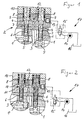
- a shift rod 1 of a transmission 2 is assigned a spring-loaded ball 3 as a fixing element and a spring-loaded shift pin 4 as an adjusting element.
- the ball 3 is positively enclosed in a concave annular groove 5 of the shift rod 1, wherein it is supported with a first spring 6 against a stop 7 of the shift pin 4.
- the first spring 6 has such a spring force that the shift rod 1 can be shifted in the axial direction.
- the ball 3 is acted on by a second spring 8 which is arranged on the side of the switching pin facing away from the ball 3 and which is designed to be stronger than the spring 6.
- the second spring 8 has a larger diameter than the first spring 6. With one end it is supported against a stop 9 of the switching pin 4 and with an opposite end against a housing part 10, which is preferably designed as a cover part 10.
- the cavity which receives the switching pin 4 is connected via a transverse bore 12 to a cavity of the same design and having the same components.
- the edge-side cavity has a pressure medium connection 13, by means of which a pressure medium conveyed by a pump 14 can be fed into the central region.
- the pump 14 forms, together with a switching valve 15 and a tank 16, a hydraulic control device 17 which keeps the cavity in the holding position of the switching pin 4 according to FIG. 1 depressurized and pressurized in a switching position of the switching pin 4 according to FIG.
- the switching valve 15 switching means designed as a 3/2-way valve in the open position according to FIG.
- the switching pin 4 is displaced in the radial direction away from the switching rod 1 against the spring action of the second spring 8, so that now only the first spring 6, supported on the stop 7, the ball 3 in the annular groove 5.
- the front end of the switching pin 4 facing the switching rod 1 is spaced apart from the ball 3, while the end of the switching pin 4 facing away from the switching rod 1 bears against the inside of the cover part 10.
- the ball 3 is acted upon by the spring 6 with a fixing force which allows a gear change.
- a shift rod 1 ' according to FIG. 2, is moved in the axial direction while moving the ball 3 out of the trough-shaped annular groove 5.
- the oppositely acting spring 6 causes the ball 3 to engage in the next switching groove 5 in the next switching position.
- the switching valve 15 In the holding position of the switching pin 4 according to FIG. 1, the switching valve 15 is switched into the blocking position, so that the second spring 8 presses the fixing spring 6 and the end of the switching pin 4 facing the switching rod 1 against the ball 3 with a larger fixing force the ball 3 holds in the annular groove 5 of the shift rod 1. If the electrical power supply or the hydraulic control device 17 fails, the exemplary embodiment described is intrinsically safe, ie the switching pin 4 is in the holding position, so that a gear change is only possible when a greater switching force is applied.
- Relief of the ball 3 occurs only when pressure is applied to the central region 11, in which there is a central piece 18 of the switching pin 4 that widens conically against the switching rod 1, so that it is only held with a reduced fixing force.
- the switching pin 4 extends from the central region 11 or from the transverse bore 12 in the direction of the shift rod 1, forming a sliding fit in the direction of the ball 3.
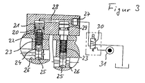
- a switching pin 20 in a Recording a piston 21 be.
- the piston 21 has an annular Stop 22 on which a fixing spring 23 can be supported to an opposite one front end a ball 24 in an annular groove 25 of a shift rod 26 to fix.
- the piston 21 is on the shift pin 20 opposite side with a pressure medium connection 27 via transverse bores 28 with a Pressure medium source 31 connected.
- a switching valve 30 is switched to the through position, so that the Piston 21 is acted upon by the pressure medium and the ball 24 with a fixing spring 23 compressive locking force in the annular groove 25 holds.
- the blocking position of the switching valve 30 there is no connection between a pressure medium source 31 and the pressure medium connection 27, so that only the fixing spring 23 with a lower fixing force the ball 24 acts.
- Figure 4 shows a partial section of a further embodiment of the invention Device with a further connection 51. Via this connection 51, the axial Direction of the switching pin 4 of the end region 50 opposite the ball 3 with a Pressure medium are applied.
- the connection 51 is in this embodiment with a Switch valve 15 connected in the control device 17 and can therefore be independent of the Pressure medium supply of the connection 13 can be supplied with pressure medium.
- This Embodiment represents the highest flexibility for the control of the device a failure of the pressure medium supply, for example when the drive motor is at a standstill of the vehicle, the shift pin 4 is in the holding position and the shift rod securely held by an increased holding force of the spring 8.
- Figure 5 differs from Figure 4 by a simplified, more cost-effective Control of the two connections 13, 51 with pressure medium.
- the pressure medium source 14 of the Control device 17 is constantly connected to connection 13.
- the connection 51 is connected to the switching valve 15 and, depending on the switching position, can be connected 51 connect to the pressure medium source 14 or the tank 16. If the connection 51 acted on by pressure medium, a locking force acts on the shift rod 1.
- the switching pin 4 is in the switching position shifted and the transmission can be shifted easily.
- This configuration of the Device has the advantage over the device shown in Figure 3 that at a failure of the pressure medium source 14, the shift rod 1 due to the increased holding force of the Switch pin 4 is held securely.
- FIG. 6 shows a schematic application of the device according to the invention, in accordance with the embodiment in FIG. 4, in connection with further devices of a vehicle.
- the driving lever 34 is usually used to actuate a hydrostatic drive unit 35.
- the drive unit 35 has an adjusting pump 36 and a constant motor 37. Via the movement of the drive lever 34, the variable pump 36 can supply the constant motor 35 with different delivery quantities and with two opposite delivery directions.
- the constant motor 37 is connected to a number of wheels 38 via the transmission 2.
- the constant motor 37 rotates in a first direction, the transmission 2 providing the torque to the wheels 38 in a forward direction.
- the constant motor 37 When the drive is moved in the opposite direction according to arrow 40, the constant motor 37 is actuated in the opposite direction of rotation, so that the wheels 38 rotate in the opposite direction.
- the position of the drive lever 34 is recognized by a switch or a measuring device 33 and is available to the control device 55 for further use.
- the quantity delivered by the variable displacement pump 36 can be short-circuited by a short-circuit valve 57, so that the constant motor 37 then does not deliver a dimming torque to the transmission 2.
- the short-circuit valve 57 can be controlled electromagnetically or, as shown, by means of a hydraulic pilot control. The control shown is particularly advantageous since it can be carried out in connection with the control of the device 60 according to the invention without additional components.
- control device 55 is connected to a device 65, by means of which the position of the shift lever 53 or the selected gear ratio of the transmission 2 can be recognized.
- a button 56 is also attached to the shift lever 53, with which the operator of the vehicle can inform the control device of his intention to shift.
- the switching pin in the device 60 is shifted from its holding position into its switching position by means of the control device 17 and the operator can then carry out a gear change with a low switching force when the vehicle is at a standstill.
- the short-circuit valve 57 By simultaneously activating the short-circuit valve 57, the gear change can also be carried out when the driving lever 34 is in a deflected position.
- the gears used in self-propelled agricultural machinery are usually not synchronized.
- a gear change should therefore advantageously only be carried out or permitted when the machine is at a standstill or only at a low driving speed.
- a speed sensor 67 is attached to the drive shaft of the wheels 38, which determines the driving speed and makes it available to the control device 55.
- the operator of the harvesting machine when the button 56 is actuated and the driving speed is too high, can be prevented from changing gears by applying the blocking force to the shift rod or can be warned of an unauthorized intention to change gears by a simple corresponding message on an existing display.
- the spring 8 can be designed in such a way that it reduces the driving speed of the vehicle, which is caused by a movement of the driving lever, cannot come to an unwanted gang jumper.
- By querying the driving lever position it is also possible to reduce the deflection to reduce the Driving speed, including the shift rod due to the application of a locking force, to protect against gang jumpers.
- the shift rod with a locking force to be applied when the vehicle is braked by a brake 61.
- the position of a brake actuator such For example, query a brake pedal 41 by a switch 68 or rotary encoder.
- the hydrostatic drive unit 35 can for the first time as Brake are used and thereby reduces the braking power previously required and the brake 61 can be carried out at a reduced cost.
- the actuation of the shift rod 1 with a locking force has the control of Control device 17 has top priority only at higher driving speeds. Will one below the specified driving speed, the braking effect of the hydrostatic Drive unit 35 only very small. In addition, when the vehicle is almost at a standstill and actuated brake, for example to hold the vehicle on a slope, a gear change be made possible. By including the driving speed in the control the control device, it is possible to apply the fully automated Realize shift rod with different fixing forces.
- the hydraulic control device 17 can be designed as a pneumatic or electromagnetic control device.
- the hydraulic control device 17 can also be deduced that other combinations in Connection to other vehicle devices for prevention and control to provide certain fixing forces on the shift rod. Including electrical data transmission means or mechanical couplings and thus connected further control options of the device in connection with the described device and the method are no further inventive solutions.
Landscapes
- Engineering & Computer Science (AREA)
- General Engineering & Computer Science (AREA)
- Mechanical Engineering (AREA)
- Gear-Shifting Mechanisms (AREA)
- Control Of Transmission Device (AREA)
- Structure Of Transmissions (AREA)
Abstract
Description
Eine vorteilhafte Anordnung der beiden Federn ergibt sich, wenn sie koaxial zueinander angeordnet sind und eine entgegengesetzte Verstellwirkung auf den Schaltstift haben. Die beiden Federn sind hierbei vorteilhaft axial voneinander beabstandet angeordnet.
Desweiteren kann durch die Einbeziehung der Fahrhebelstellung verhindert werden, daß die Schaltstange bei Stillstand des Fahrzeuges mit einer Sperrkraft beaufschlagt wird. Die Ansteuerung der Steuereinrichtung kann so erfolgen, daß dies erst bei der Überschreitung einer bestimmten Fahrhebelauslenkung möglich ist.
- Figur 1
- einen Teilschnitt der erfindungsgemäßen Vorrichtung in doppelter Ausführung, wobei sich die Schaltstifte in der Halteposition befindet,
- Figur 2
- einen Teilschnitt der Vorrichtung nach Figur 1, wobei sich die Schaltstifte in der Schaltposition befinden,
- Figur 3
- einen Teilschnitt eines weiteren Ausführungsbeispiels der erfindungsgemäßen Vorrichtung,
- Figur 4
- einen Teilschnitt eines Ausführungsbeispiels der erfindungsgemäßen Vorrichtung mit weiterem Anschluß,
- Figur 5
- einen Teilschnitt der Vorrichtung nach Figur 4 mit vereinfachte Ansteuerung und
- Figur 6
- eine schematische Darstellung der Anwendung der erfindungsgemäßen Vorrichtung in Verbindung mit weiteren Einrichtungen des Fahrzeuges.
In der dargestellten Halteposition des Schaltstiftes 4, wirkt auf die Kugel 3 eine auf der Kugel 3 abgewandten Seite des Schaltstiftes angeordnete zweite Feder 8 ein, die stärker als die Feder 6 ausgebildet ist. Diese weist eine solche Federkraft auf, daß der Schaltstift 4 bzw. die Kugel 3 mit einer größeren Kraft beaufscblagt, d.h. die Schaltstange 1 kann in axialer Richtung nur unter einer größeren Betätigungskraft verschoben werden. Die zweite Feder 8 weist einen größeren Durchmesser aufals die erste Feder 6. Mit einem stirnseitigen Ende stützt sie sich gegen einen Anschlag 9 des Schaltstiftes 4 und mit einem gegenüberliegenden Ende gegen ein Gehäuseteil 10 ab, das vorzugsweise als Deckelteil 10 ausgebildet ist.
In der Halteposition des Schaltstiftes 4 gemäß Figur 1 ist das Schaltventil 15 in Sperrstellung geschaltet, so daß die zweite Feder 8 unter Zusammendrücken der Fixierfeder 6 und unter Anlage des der Schaltstange 1 zugewandten Endes des Schaltstiftes 4 an der Kugel 3 mit einer größeren Fixierkraft die Kugel 3 in der Ringnut 5 der Schaltstange 1 hält. Bei Ausfall der elektrischen Stromversorgung bzw. der hydraulischen Steuereinrichtung 17 ist das beschriebene Ausführungsbeispiel eigensicher, d.h. der Schaltstift 4 befindet sich in der Halteposition, so daß ein Gangwechsel nur unter Aufbringung einer größeren Schaltkraft möglich ist. Erst durch Druckbeaufschlagung des mittleren Bereiches 11, in dem ein sich entgegen der Schaltstange 1 konusförmig verbreiterndes Mittelstück 18 des Schaltstiftes 4 befindet, tritt eine Entlastung der Kugel 3 ein, so daß sie lediglich mit einer verminderten Fixierkraft gehalten ist. Vom mittleren Bereich 11 bzw. von der Querbohrung 12 in Richtung der Schaltstange 1 erstreckt sich der Schaltstift 4 unter Bildung einer Gleitpassung in Richtung der Kugel 3.
Zur Ansteuerung der Steuereinrichtung 17 ist die Ansteuereinrichtung 55 mit einer Einrichtung 65 verbunden, mittels welcher die Stellung des Schalthebels 53 beziehungsweise die gewählte Übersetzung des Getriebes 2 erkannt werden kann. An dem Schalthebel 53 ist ferner ein Taster 56 abgebracht, mit welchem der Bediener des Fahrzeuges der Ansteuereinrichtung seine Schaltabsicht mitteilen kann. In der einfachsten Ausführungsform der Ansteuereinrichtung 55, wird durch die Betätigung des Tasters 56 der Schaltstift in der Vorrichtung 60 mittels der Steuereinrichtung 17 aus seiner Halteposition in seine Schaltposition verschoben und der Bediener kann dann mit geringer Schaltkraft einen Gangwechsel bei Stillstand des Fahrzeuges durchführen. Durch eine gleichzeitige Ansteuerung des Kurzschlußventils 57 kann der Gangwechsel auch bei einer ausgelenkten Stellung des Fahrhebels 34 durchgeführt werden. Die in selbstfahrenden Landmaschinen verwendeten Getriebe sind in der Regel nicht synchronisiert. Vorteilhaft sollte daher einen Gangwechsel nur bei Stillstand der Maschine oder nur bei einer geringer Fahrgeschwindigkeit vorgenommen beziehungsweise zuzulassen werden. Dafür ist an der Antriebswelle der Räder 38 ein Drehzahlgeber 67 angebracht, der die Fahrgeschwindigkeit ermittelt und der Ansteuereinrichtung 55 zu Verfügung stellt. So kann beispielsweise dem Bediener der Erntemaschine, bei der Betätigung des Tasters 56 und einer vorhanden zu hohen Fahrgeschwindigkeit, ein Gangwechsel durch eine Beaufschlagung der Schaltstange mit der Sperrkraft verwehrt werden oder auch durch eine einfache entsprechende Mitteilung in einem vorhandenem Display aufeine unerlaubte Gangwechselabsicht hingewiesen werden.
Claims (28)
- Vorrichtung an mehrgängigen Schaltgetrieben mit mindestens einer Schaltstange, die in jeweils einer vorgegebenen Stellung mit mindestens einem Fixierelement zum Fixieren der Schaltstange beaufschlagbar ist,
dadurch gekennzeichnet, daßdas Fixierelement (3, 24) mit einem Stellelement (4, 20) derart wirkverbunden ist,daß das Stellelement (4, 20) mittels einer Steuereinrichtung (17) in mindestens zwei unterschiedliche Positionen zum Fixierelement (3, 24) einstellbar ist. - Vorrichtung nach Anspruch 1,
dadurch gekennzeichnet, daßdas Stellelement (4, 20) in zwei Positionen bringbar ist, wobei das Fixierelement (3, 24) die Schaltstange (1) in einer ersten Schaltposition mit einer Fixierkraft und in einer zweiten Halteposition mit einer größeren Fixierkraft beaufschlagt. - Vorrichtung nach Anspruch 1 oder 2,
dadurch gekennzeichnet, daßdas Fixierelement (3, 24) wirkverbunden durch eine Feder (6) in der Schaltposition des Stellelementes mit einer Fixierkraft und in der Halteposition durch ein federgespanntes Stellelement (4) direkt mit einer größeren Fixierkraft beaufschlagt wird. - Vorrichtung nach einem der Ansprüche 1 bis 3,
dadurch gekennzeichnet, daßdas Stellelement (4, 20) als Schaltstift (4, 20) ausgebildet ist, der mittels einer Steuereinrichtung (17) durch axiale Verschiebung von der Schaltposition in die Halteposition und vice versa bringbar ist. - Vorrichtung nach einem der Ansprüche 1 bis 4,
dadurch gekennzeichnet, daßder Schaltstift (4, 20) mittels einer hydraulischen Steuereinrichtung (17) betätigbar ist. - Vorrichtung nach einem der Ansprüche 1 bis 5,
dadurch gekennzeichnet, daßdem Schaltstift (4) eine erste Feder (6) und eine zweite Feder (8) zugeordnet ist, wobei die Federn (6, 8) in gegenläufiger Verstellung zu dem Schaltstift (4) angeordnet sind. - Vorrichtung nach einem der Ansprüche 1 bis 6,
dadurch gekennzeichnet, daßdie erste Feder (6) mit einem ersten Ende an dem Fixierelement (3) anliegt und sich mit dem anderen gegenüberliegenden Ende gegen einen ersten Anschlag (7) des Schaltstiftes (4) abstützt. - Vorrichtung nach einem der Ansprüche 1 bis 7,
dadurch gekennzeichnet, daßdie zweite Feder (8) mit einem ersten Ende gegen ein Gehäuseteil (10) und mit einem gegenüberliegenden Ende gegen einen zweiten Anschlag (9) des Schaltstiftes (4) abstützt. - Vorrichtung nach einem der Ansprüche 1 bis 8,
dadurch gekennzeichnet, daßdie erste und zweite Feder (6, 8) zum Schaltstift (4) koaxial und axial versetzt zueinander angeordnet sind. - Vorrichtung nach einem der Ansprüche 1 bis 9,
dadurch gekennzeichnet, daßder Schaltstift (4) in einem in axialer Richtung zwischen der ersten Feder (6) und der zweiten Feder (8) liegenden Bereich (11) über einen Anschluß (13) mit der Steuereinrichtung (17) verbunden ist. - Vorrichtung nach einem der Ansprüche 1 bis 10,
dadurch gekennzeichnet, daßder Schaltstift (4) an dem dem Fixierelement (3) gegenüberliegenden Stirnbereich (50) über einen Anschluß (51) mit der Steuereinrichtung (17) verbunden ist. - Vorrichtung nach einem der Ansprüche 1 bis 11,
dadurch gekennzeichnet, daßdie Steuereinrichtung (17) mindestens ein Schaltventil (15) und mindestens eine Druckmittelquelle (14) aufweist, mittels welcher der Schaltstift (4) entsprechend der Ansteuerung der Steuereinrichtung (17) beaufschlagt werden kann. - Vorrichtung nach Anspruch 12,
dadurch gekennzeichnet, daßmittels der Steuereinrichtung (17) weitere Einrichtungen in Verbindung mit der Ansteuerung des Schaltstiftes (4) angesteuert werden können. - Vorrichtung nach einem der Ansprüche 12 oder 13,
dadurch gekennzeichnet, daßdie weitere Einrichtungen ein Kurzschlußventil im hydrostatischen Antriebsstang ist. - Vorrichtung nach einem der Ansprüche 1 bis 14,
dadurch gekennzeichnet, daßbei einer Ansteuerung der Steuervorrichtung (17) der Schaltstift (4) aus seiner Halteposition in seine Schaltposition mit niedrigerer Fixierkraft gebracht wird. - Vorrichtung nach einem der Ansprüche 1 bis 15,
dadurch gekennzeichnet, daßdie Ansteuerung der Steuervorrichtung (17) derart erfolgt, daß der Schaltstift (4) entgegen der Federwirkung der zweiten Feder (8) verschoben wird. - Vorrichtung nach einem der Ansprüche 1 bis 16,
dadurch gkennzeichnet, daßdie Ansteuerung der Steuereinrichtung (17) derart erfolgt, daß das Fixierelement (3) in der Halteposition des Stellelementes (4) zusätzlich mit einer Sperrkraft beaufschlagt wird. - Vorrichtung nach einem der Ansprüche 1 bis 17,
dadurch gekennzeichnet, daßdie Ansteuerung der Steuereinrichtung (17) unter Berücksichtigung weiterer auf die Fahrgeschwindigkeit des Fahrzeuges einflußnehmenden Einrichtungen, wie beispielsweise die Fahrzeugbremseinrichtung oder der hydrostatischen Antriebseinheit oder dessen Stelleinrichtungen durchgeführt wird. - Vorrichtung nach Anspruch 16,
dadurch gekennzeichnet, daßdas bei der Ansteuerung der Steuereinrichtung (17) die Stellung des Fahrhebel (34) berücksichtig wird. - Vorrichtung nach Anspruch 18 oder 19,
dadurch gekennzeichnet, daßbei der Ansteuerung der Steuereinrichtung (17) die Stellung des Schalthebeis (53) beziehungsweise die Stellung eines an diesem angebrachten Tasters (56) berücksichtig wird. - Vorrichtung nach einem der Ansprüche 18 bis 20,
dadurch gekennzeichnet, daßbei der Ansteuerung der Steuereinrichtung (17) die Stellung einer Bremsbetätigungseinrichtung (54) berücksichtig wird. - Verfahren zur Steuerung einer Vorrichtung nach mindestens einem der Ansprüche 1 bis 21,
dadurch gekennzeichnet, daßdurch die Betätigung des Tasters (56) das Stellelement (4,20) aus der Halteposition in die Schaltposition verstellt wird. - Verfahren nach der Anspruch 22,
dadurch gekennzeichnet, daßgleichzeitig mit der Verstellung des Stellelementes (4, 20) in die Schaltposition auch das Kurzschlußventil (57) betätigt wird. - Verfahren nach einem der Ansprüche 22 bis 23,
dadurch gekennzeichnet, daßdie Bewegung des Stellelementes (4, 20) nur dann erfolgt, wenn eine bestimmte Fahrgeschwindigkeit des Fahrzeuges unterschritten ist. - Verfahren nach einem der Ansprüche 22 bis 24,
dadurch gekennzeichnet, daßdie Bewegung des Stellelementes (4, 20) nur dann erfolgt, wenn der Fahrhebel sich in seiner Neutralstellung befindet. - Verfahren nach einem der Ansprüche 22 bis 25,
dadurch gekennzeichnet, daßdas Stellelemente (4,) mit einer Sperrkraft beaufschlagt wird, wenn die Bremseinrichtung betätigt wird. - Verfahren nach Anspruch 26,
dadurch gekennzeichnet, daßdas Stellelemente (4,) nur dann mit einer Sperrkraft beaufschlagt wird, wenn ein oder ein bestimmter Gang im Schaltgetriebe (2) eingelegt ist. - Verfahren nach einem der Ansprüche 25 oder 26,
dadurch gekennzeichnet, daßdas Stellelement (4,) nur dann mit einer Sperrkraft beaufschlagt wird, wenn der Fahrhebel sich außerhalb seiner Neutralstellung befindet.
Applications Claiming Priority (2)
| Application Number | Priority Date | Filing Date | Title |
|---|---|---|---|
| DE19840849A DE19840849C2 (de) | 1998-09-07 | 1998-09-07 | Vorrichtung zum Arretieren einer Schaltstange |
| DE19840849 | 1998-09-07 |
Publications (3)
| Publication Number | Publication Date |
|---|---|
| EP0985859A2 true EP0985859A2 (de) | 2000-03-15 |
| EP0985859A3 EP0985859A3 (de) | 2001-04-11 |
| EP0985859B1 EP0985859B1 (de) | 2005-10-26 |
Family
ID=7880131
Family Applications (1)
| Application Number | Title | Priority Date | Filing Date |
|---|---|---|---|
| EP99117071A Expired - Lifetime EP0985859B1 (de) | 1998-09-07 | 1999-08-31 | Vorrichtung an mehrgängigen Schaltgetrieben |
Country Status (7)
| Country | Link |
|---|---|
| US (1) | US6269708B1 (de) |
| EP (1) | EP0985859B1 (de) |
| AT (1) | ATE307994T1 (de) |
| BR (1) | BR9904121A (de) |
| DE (2) | DE19840849C2 (de) |
| RU (1) | RU2241165C2 (de) |
| UA (1) | UA50812C2 (de) |
Cited By (2)
| Publication number | Priority date | Publication date | Assignee | Title |
|---|---|---|---|---|
| CN102537339A (zh) * | 2012-01-15 | 2012-07-04 | 福田雷沃国际重工股份有限公司 | 变速箱拨叉轴自锁与互锁机构 |
| WO2018217886A1 (en) * | 2017-05-24 | 2018-11-29 | Ghsp, Inc. | Transmission shifter with improved feel positioner |
Families Citing this family (8)
| Publication number | Priority date | Publication date | Assignee | Title |
|---|---|---|---|---|
| DE10104420A1 (de) * | 2001-02-01 | 2002-08-08 | Zahnradfabrik Friedrichshafen | Synchrongetriebe |
| US6694590B1 (en) * | 2002-03-29 | 2004-02-24 | Honda Giken Kogyo Kabushiki Kaisha | Method of setting automotive transmission gear selector position |
| US6935204B2 (en) | 2003-10-31 | 2005-08-30 | Caterpillar Inc | Automated manual transmission and shift method |
| EP1632696B1 (de) * | 2004-09-03 | 2011-12-07 | Schaeffler Technologies AG & Co. KG | Verfahren und Vorrichtung zum Verhindern des Einlegens eines unzulässigen Gangs bei einem automatisierten Schaltgetriebe |
| DE102006048198A1 (de) * | 2005-12-16 | 2007-07-12 | Bosch Rexroth Ag | Hydrostatischer Antrieb und Verfahren zum Abbremsen eines hydrostatischen Antriebs |
| RU2483949C2 (ru) * | 2011-06-09 | 2013-06-10 | Федеральное государственное образовательное учреждение высшего профессионального образования "Санкт-Петербургский государственный аграрный университет" | Предохранительное устройство для транспортного средства |
| JP5708808B2 (ja) * | 2011-08-03 | 2015-04-30 | トヨタ自動車株式会社 | 切替バルブ |
| DE102014215914B4 (de) * | 2014-08-12 | 2017-03-02 | Schaeffler Technologies AG & Co. KG | Schaltdom und Schaltarretierung zur Erzeugung von variablen Schaltkräften |
Family Cites Families (14)
| Publication number | Priority date | Publication date | Assignee | Title |
|---|---|---|---|---|
| GB1385909A (en) * | 1971-05-14 | 1975-03-05 | Cav Ltd | Gear change mechanism |
| SU695861A1 (ru) * | 1977-10-05 | 1979-11-05 | Волгоградский Политехнический Институт | Механизм блокировки коробки передач транспортного средства |
| DE3046885C2 (de) * | 1980-12-12 | 1984-12-13 | Zahnradfabrik Friedrichshafen Ag, 7990 Friedrichshafen | Vorrichtung für ein Schaltgetriebe |
| DE73280T1 (de) * | 1981-08-26 | 1983-08-04 | Deere & Co., 61265 Moline, Ill. | Anordnung fuer die gangschaltung fuer ein fahrzeug. |
| DE3141271C2 (de) * | 1981-10-17 | 1984-04-26 | Zahnradfabrik Friedrichshafen Ag, 7990 Friedrichshafen | Fahrgeschwindigkeitsabhängige Schaltvorrichtung |
| DE3315221A1 (de) * | 1983-04-27 | 1984-10-31 | Wabco Westinghouse Fahrzeugbremsen GmbH, 3000 Hannover | Betaetigungseinrichtung zum schalten von gaengen und gassen eines fahrzeug-getriebes |
| US4856628A (en) * | 1987-11-17 | 1989-08-15 | Hino Jidosha Kogyo Kabushiki Kaisha | Automated mechanical transmission system for use in commercial vehicles |
| FR2645233A1 (fr) * | 1989-03-20 | 1990-10-05 | Redele Jean | Dispositif pour rendre plus souple le changement de rapport dans les boites de vitesses de vehicules |
| US5161422A (en) * | 1991-07-12 | 1992-11-10 | Prince Corporation | Universal control for electrically controlled vehicle transmission |
| DE4312997A1 (de) * | 1993-04-21 | 1994-10-27 | Schaeffler Waelzlager Kg | Schaltarretierung |
| US5845224A (en) * | 1995-10-19 | 1998-12-01 | Case Corporation | Method and apparatus for preselecting gear ratios in a power transmission |
| DE19610491A1 (de) * | 1996-03-18 | 1997-09-25 | Hydraulik Ring Gmbh | Stelleinrichtung zur Automatisierung von Handschaltgetrieben von Kraftfahrzeugen |
| DE19647788B4 (de) * | 1996-10-14 | 2011-06-09 | Volkswagen Ag | Gangsperre für ein Schaltgetriebe |
| DE19735844A1 (de) * | 1997-08-19 | 1999-02-25 | Zahnradfabrik Friedrichshafen | Kupplungsabhängige Getrieberastierung |
-
1998
- 1998-09-07 DE DE19840849A patent/DE19840849C2/de not_active Expired - Fee Related
-
1999
- 1999-08-30 RU RU99118758/11A patent/RU2241165C2/ru not_active IP Right Cessation
- 1999-08-31 EP EP99117071A patent/EP0985859B1/de not_active Expired - Lifetime
- 1999-08-31 DE DE59912703T patent/DE59912703D1/de not_active Expired - Lifetime
- 1999-08-31 AT AT99117071T patent/ATE307994T1/de not_active IP Right Cessation
- 1999-09-03 US US09/389,568 patent/US6269708B1/en not_active Expired - Fee Related
- 1999-09-06 UA UA99094952A patent/UA50812C2/uk unknown
- 1999-09-08 BR BR9904121-9A patent/BR9904121A/pt not_active IP Right Cessation
Cited By (3)
| Publication number | Priority date | Publication date | Assignee | Title |
|---|---|---|---|---|
| CN102537339A (zh) * | 2012-01-15 | 2012-07-04 | 福田雷沃国际重工股份有限公司 | 变速箱拨叉轴自锁与互锁机构 |
| WO2018217886A1 (en) * | 2017-05-24 | 2018-11-29 | Ghsp, Inc. | Transmission shifter with improved feel positioner |
| US11280400B2 (en) | 2017-05-24 | 2022-03-22 | Ghsp, Inc. | Transmission shifter with improved feel positioner |
Also Published As
| Publication number | Publication date |
|---|---|
| RU2241165C2 (ru) | 2004-11-27 |
| EP0985859B1 (de) | 2005-10-26 |
| EP0985859A3 (de) | 2001-04-11 |
| US6269708B1 (en) | 2001-08-07 |
| DE59912703D1 (de) | 2005-12-01 |
| DE19840849C2 (de) | 2001-09-27 |
| DE19840849A1 (de) | 2000-03-16 |
| ATE307994T1 (de) | 2005-11-15 |
| UA50812C2 (uk) | 2002-11-15 |
| BR9904121A (pt) | 2000-09-26 |
Similar Documents
| Publication | Publication Date | Title |
|---|---|---|
| DE3815225C2 (de) | ||
| DE69707058T2 (de) | Getriebeschaltvorrichtung mit Kugel-Rampen-Betätigungseinrichtung | |
| EP3691943A1 (de) | Mechanische bremsvorrichtung | |
| DE3918565C2 (de) | ||
| EP1934082B1 (de) | Überlagerungslenkung mit mechanischer rückfallebene | |
| DE69405336T2 (de) | Mechanisches Getriebe für Antriebsräder, insbesondere für fahrbare Arbeitmaschine | |
| DE102017205103A1 (de) | Arbeitsfahrzeug-antriebseinheit | |
| DE102012208630A1 (de) | Handschaltgetriebe-Kupplungsschutzvorrichtung | |
| DE10131735A1 (de) | Parksperre für Fahrzeuggetriebe | |
| DE60123010T2 (de) | Radnabe mit integriertem Planetengetriebe und Lamellenbremse | |
| EP0985859B1 (de) | Vorrichtung an mehrgängigen Schaltgetrieben | |
| WO2023241970A1 (de) | Antriebsstrang für ein elektrofahrzeug und elektrofahrzeug | |
| EP0368140A2 (de) | Verfahren zum Verstellen von Reibungskupplungen oder -bremsen | |
| DE19741865C1 (de) | Bremsaktuator | |
| EP0807561A2 (de) | Rücklaufsperre für Kraftfahrzeuge | |
| EP1794045A1 (de) | Bremszylinder für fahrzeugbremsen | |
| EP2130742B1 (de) | Überlagerungslenkung mit Bremseinrichtung | |
| DE4206102C2 (de) | Hydromechanisches Getriebe | |
| AT4939U1 (de) | Differentialgetriebe mit sperrkupplung und mit einer solchen ausgestattetes verteilergetriebe für kraftfahrzeuge | |
| EP1825739A1 (de) | Verstellgetriebeanordnung insbesondere für Düngersteuer | |
| DE102021109712A1 (de) | Schalteinheit und Antriebseinheit für einen elektrifizierten Antriebsstrang eines Kraftfahrzeugs sowie Achsmodul | |
| DE69121779T2 (de) | Hydrostatisch angetriebene Achse und Bremsenanordnung für diese Achse | |
| EP1181178B1 (de) | Radantrieb für ein mobilfahrzeug | |
| EP0763443B1 (de) | Antriebseinrichtung für ein Kraftfahrzeug | |
| DE102023200554A1 (de) | Parksperrenvorrichtung, insbesondere Parksperrenvorrichtung eines Automatgetriebes |
Legal Events
| Date | Code | Title | Description |
|---|---|---|---|
| PUAI | Public reference made under article 153(3) epc to a published international application that has entered the european phase |
Free format text: ORIGINAL CODE: 0009012 |
|
| AK | Designated contracting states |
Kind code of ref document: A2 Designated state(s): AT BE CH CY DE DK ES FI FR GB GR IE IT LI LU MC NL PT SE |
|
| AX | Request for extension of the european patent |
Free format text: AL;LT;LV;MK;RO;SI |
|
| PUAL | Search report despatched |
Free format text: ORIGINAL CODE: 0009013 |
|
| AK | Designated contracting states |
Kind code of ref document: A3 Designated state(s): AT BE CH CY DE DK ES FI FR GB GR IE IT LI LU MC NL PT SE |
|
| AX | Request for extension of the european patent |
Free format text: AL;LT;LV;MK;RO;SI |
|
| 17P | Request for examination filed |
Effective date: 20011011 |
|
| AKX | Designation fees paid |
Free format text: AT BE CH CY DE DK ES FI FR GB GR IE IT LI LU MC NL PT SE |
|
| 17Q | First examination report despatched |
Effective date: 20030306 |
|
| GRAP | Despatch of communication of intention to grant a patent |
Free format text: ORIGINAL CODE: EPIDOSNIGR1 |
|
| RTI1 | Title (correction) |
Free format text: DEVICE FOR MULTISPEED SHIFT GEARBOXES |
|
| GRAS | Grant fee paid |
Free format text: ORIGINAL CODE: EPIDOSNIGR3 |
|
| GRAP | Despatch of communication of intention to grant a patent |
Free format text: ORIGINAL CODE: EPIDOSNIGR1 |
|
| GRAA | (expected) grant |
Free format text: ORIGINAL CODE: 0009210 |
|
| AK | Designated contracting states |
Kind code of ref document: B1 Designated state(s): AT BE CH CY DE DK ES FI FR GB GR IE IT LI LU MC NL PT SE |
|
| PG25 | Lapsed in a contracting state [announced via postgrant information from national office to epo] |
Ref country code: NL Free format text: LAPSE BECAUSE OF FAILURE TO SUBMIT A TRANSLATION OF THE DESCRIPTION OR TO PAY THE FEE WITHIN THE PRESCRIBED TIME-LIMIT Effective date: 20051026 Ref country code: IT Free format text: LAPSE BECAUSE OF FAILURE TO SUBMIT A TRANSLATION OF THE DESCRIPTION OR TO PAY THE FEE WITHIN THE PRESCRIBED TIME-LIMIT;WARNING: LAPSES OF ITALIAN PATENTS WITH EFFECTIVE DATE BEFORE 2007 MAY HAVE OCCURRED AT ANY TIME BEFORE 2007. THE CORRECT EFFECTIVE DATE MAY BE DIFFERENT FROM THE ONE RECORDED. Effective date: 20051026 Ref country code: IE Free format text: LAPSE BECAUSE OF FAILURE TO SUBMIT A TRANSLATION OF THE DESCRIPTION OR TO PAY THE FEE WITHIN THE PRESCRIBED TIME-LIMIT Effective date: 20051026 Ref country code: FI Free format text: LAPSE BECAUSE OF FAILURE TO SUBMIT A TRANSLATION OF THE DESCRIPTION OR TO PAY THE FEE WITHIN THE PRESCRIBED TIME-LIMIT Effective date: 20051026 |
|
| REG | Reference to a national code |
Ref country code: GB Ref legal event code: FG4D Free format text: NOT ENGLISH |
|
| REG | Reference to a national code |
Ref country code: CH Ref legal event code: EP |
|
| GBT | Gb: translation of ep patent filed (gb section 77(6)(a)/1977) |
Effective date: 20051026 |
|
| REG | Reference to a national code |
Ref country code: IE Ref legal event code: FG4D Free format text: LANGUAGE OF EP DOCUMENT: GERMAN |
|
| REF | Corresponds to: |
Ref document number: 59912703 Country of ref document: DE Date of ref document: 20051201 Kind code of ref document: P |
|
| PG25 | Lapsed in a contracting state [announced via postgrant information from national office to epo] |
Ref country code: SE Free format text: LAPSE BECAUSE OF FAILURE TO SUBMIT A TRANSLATION OF THE DESCRIPTION OR TO PAY THE FEE WITHIN THE PRESCRIBED TIME-LIMIT Effective date: 20060126 Ref country code: GR Free format text: LAPSE BECAUSE OF FAILURE TO SUBMIT A TRANSLATION OF THE DESCRIPTION OR TO PAY THE FEE WITHIN THE PRESCRIBED TIME-LIMIT Effective date: 20060126 Ref country code: DK Free format text: LAPSE BECAUSE OF FAILURE TO SUBMIT A TRANSLATION OF THE DESCRIPTION OR TO PAY THE FEE WITHIN THE PRESCRIBED TIME-LIMIT Effective date: 20060126 |
|
| PG25 | Lapsed in a contracting state [announced via postgrant information from national office to epo] |
Ref country code: ES Free format text: LAPSE BECAUSE OF FAILURE TO SUBMIT A TRANSLATION OF THE DESCRIPTION OR TO PAY THE FEE WITHIN THE PRESCRIBED TIME-LIMIT Effective date: 20060206 |
|
| PG25 | Lapsed in a contracting state [announced via postgrant information from national office to epo] |
Ref country code: PT Free format text: LAPSE BECAUSE OF FAILURE TO SUBMIT A TRANSLATION OF THE DESCRIPTION OR TO PAY THE FEE WITHIN THE PRESCRIBED TIME-LIMIT Effective date: 20060327 |
|
| NLV1 | Nl: lapsed or annulled due to failure to fulfill the requirements of art. 29p and 29m of the patents act | ||
| ET | Fr: translation filed | ||
| PG25 | Lapsed in a contracting state [announced via postgrant information from national office to epo] |
Ref country code: MC Free format text: LAPSE BECAUSE OF NON-PAYMENT OF DUE FEES Effective date: 20060831 Ref country code: LI Free format text: LAPSE BECAUSE OF NON-PAYMENT OF DUE FEES Effective date: 20060831 Ref country code: CH Free format text: LAPSE BECAUSE OF NON-PAYMENT OF DUE FEES Effective date: 20060831 |
|
| PLBE | No opposition filed within time limit |
Free format text: ORIGINAL CODE: 0009261 |
|
| STAA | Information on the status of an ep patent application or granted ep patent |
Free format text: STATUS: NO OPPOSITION FILED WITHIN TIME LIMIT |
|
| 26N | No opposition filed |
Effective date: 20060727 |
|
| REG | Reference to a national code |
Ref country code: CH Ref legal event code: PL |
|
| PG25 | Lapsed in a contracting state [announced via postgrant information from national office to epo] |
Ref country code: AT Free format text: LAPSE BECAUSE OF NON-PAYMENT OF DUE FEES Effective date: 20060831 |
|
| PG25 | Lapsed in a contracting state [announced via postgrant information from national office to epo] |
Ref country code: LU Free format text: LAPSE BECAUSE OF NON-PAYMENT OF DUE FEES Effective date: 20060831 |
|
| PG25 | Lapsed in a contracting state [announced via postgrant information from national office to epo] |
Ref country code: CY Free format text: LAPSE BECAUSE OF FAILURE TO SUBMIT A TRANSLATION OF THE DESCRIPTION OR TO PAY THE FEE WITHIN THE PRESCRIBED TIME-LIMIT Effective date: 20051026 |
|
| PGFP | Annual fee paid to national office [announced via postgrant information from national office to epo] |
Ref country code: GB Payment date: 20100819 Year of fee payment: 12 |
|
| GBPC | Gb: european patent ceased through non-payment of renewal fee |
Effective date: 20110831 |
|
| PG25 | Lapsed in a contracting state [announced via postgrant information from national office to epo] |
Ref country code: GB Free format text: LAPSE BECAUSE OF NON-PAYMENT OF DUE FEES Effective date: 20110831 |
|
| PGFP | Annual fee paid to national office [announced via postgrant information from national office to epo] |
Ref country code: FR Payment date: 20130823 Year of fee payment: 15 |
|
| REG | Reference to a national code |
Ref country code: DE Ref legal event code: R084 Ref document number: 59912703 Country of ref document: DE Effective date: 20140621 |
|
| REG | Reference to a national code |
Ref country code: FR Ref legal event code: ST Effective date: 20150430 |
|
| PG25 | Lapsed in a contracting state [announced via postgrant information from national office to epo] |
Ref country code: FR Free format text: LAPSE BECAUSE OF NON-PAYMENT OF DUE FEES Effective date: 20140901 |
|
| PGFP | Annual fee paid to national office [announced via postgrant information from national office to epo] |
Ref country code: BE Payment date: 20150819 Year of fee payment: 17 |
|
| PGFP | Annual fee paid to national office [announced via postgrant information from national office to epo] |
Ref country code: DE Payment date: 20160629 Year of fee payment: 18 |
|
| PG25 | Lapsed in a contracting state [announced via postgrant information from national office to epo] |
Ref country code: BE Free format text: LAPSE BECAUSE OF NON-PAYMENT OF DUE FEES Effective date: 20160831 |
|
| REG | Reference to a national code |
Ref country code: DE Ref legal event code: R119 Ref document number: 59912703 Country of ref document: DE |
|
| PG25 | Lapsed in a contracting state [announced via postgrant information from national office to epo] |
Ref country code: DE Free format text: LAPSE BECAUSE OF NON-PAYMENT OF DUE FEES Effective date: 20180301 |