EP0984345A1 - Sicherheitssperrvorrichtung für einen Hebelschater - Google Patents
Sicherheitssperrvorrichtung für einen Hebelschater Download PDFInfo
- Publication number
- EP0984345A1 EP0984345A1 EP99306538A EP99306538A EP0984345A1 EP 0984345 A1 EP0984345 A1 EP 0984345A1 EP 99306538 A EP99306538 A EP 99306538A EP 99306538 A EP99306538 A EP 99306538A EP 0984345 A1 EP0984345 A1 EP 0984345A1
- Authority
- EP
- European Patent Office
- Prior art keywords
- lever
- actuator
- driving actuator
- actuating mechanism
- mechanical link
- Prior art date
- Legal status (The legal status is an assumption and is not a legal conclusion. Google has not performed a legal analysis and makes no representation as to the accuracy of the status listed.)
- Granted
Links
Images


Classifications
-
- A—HUMAN NECESSITIES
- A01—AGRICULTURE; FORESTRY; ANIMAL HUSBANDRY; HUNTING; TRAPPING; FISHING
- A01D—HARVESTING; MOWING
- A01D34/00—Mowers; Mowing apparatus of harvesters
- A01D34/01—Mowers; Mowing apparatus of harvesters characterised by features relating to the type of cutting apparatus
- A01D34/412—Mowers; Mowing apparatus of harvesters characterised by features relating to the type of cutting apparatus having rotating cutters
- A01D34/63—Mowers; Mowing apparatus of harvesters characterised by features relating to the type of cutting apparatus having rotating cutters having cutters rotating about a vertical axis
- A01D34/82—Other details
- A01D34/828—Safety devices
-
- A—HUMAN NECESSITIES
- A01—AGRICULTURE; FORESTRY; ANIMAL HUSBANDRY; HUNTING; TRAPPING; FISHING
- A01D—HARVESTING; MOWING
- A01D34/00—Mowers; Mowing apparatus of harvesters
- A01D34/01—Mowers; Mowing apparatus of harvesters characterised by features relating to the type of cutting apparatus
- A01D34/412—Mowers; Mowing apparatus of harvesters characterised by features relating to the type of cutting apparatus having rotating cutters
- A01D34/63—Mowers; Mowing apparatus of harvesters characterised by features relating to the type of cutting apparatus having rotating cutters having cutters rotating about a vertical axis
- A01D34/67—Mowers; Mowing apparatus of harvesters characterised by features relating to the type of cutting apparatus having rotating cutters having cutters rotating about a vertical axis hand-guided by a walking operator
- A01D34/68—Mowers; Mowing apparatus of harvesters characterised by features relating to the type of cutting apparatus having rotating cutters having cutters rotating about a vertical axis hand-guided by a walking operator with motor driven cutters or wheels
- A01D34/6806—Driving mechanisms
- A01D34/6818—Motor starting mechanisms
-
- G—PHYSICS
- G05—CONTROLLING; REGULATING
- G05G—CONTROL DEVICES OR SYSTEMS INSOFAR AS CHARACTERISED BY MECHANICAL FEATURES ONLY
- G05G5/00—Means for preventing, limiting or returning the movements of parts of a control mechanism, e.g. locking controlling member
- G05G5/005—Means for preventing, limiting or returning the movements of parts of a control mechanism, e.g. locking controlling member for preventing unintentional use of a control mechanism
-
- A—HUMAN NECESSITIES
- A01—AGRICULTURE; FORESTRY; ANIMAL HUSBANDRY; HUNTING; TRAPPING; FISHING
- A01D—HARVESTING; MOWING
- A01D34/00—Mowers; Mowing apparatus of harvesters
- A01D34/01—Mowers; Mowing apparatus of harvesters characterised by features relating to the type of cutting apparatus
- A01D34/412—Mowers; Mowing apparatus of harvesters characterised by features relating to the type of cutting apparatus having rotating cutters
- A01D34/63—Mowers; Mowing apparatus of harvesters characterised by features relating to the type of cutting apparatus having rotating cutters having cutters rotating about a vertical axis
- A01D34/67—Mowers; Mowing apparatus of harvesters characterised by features relating to the type of cutting apparatus having rotating cutters having cutters rotating about a vertical axis hand-guided by a walking operator
- A01D34/68—Mowers; Mowing apparatus of harvesters characterised by features relating to the type of cutting apparatus having rotating cutters having cutters rotating about a vertical axis hand-guided by a walking operator with motor driven cutters or wheels
- A01D2034/6843—Control levers on the handle of the mower
Definitions
- the present invention relates to an actuating mechanism and in particular to actuating mechanisms for use with a bowden cable on a lawn mower.
- a motor is mounted on the deck of the mower which rotatingly drives a cutting blade mounted beneath the cutting deck about a substantially vertical axis.
- a handle is attached to the rear of the mower by which an operator is able to manoeuvre the mower.
- the motor can either be an electric motor powered by either a battery or a mains electricity power supply or be a combustion engine.
- a control mechanism is commonly provided on the handle which enables the operator to control the motor whilst holding the handle of the mower.
- Such control mechanisms include a lever box mounted on the handle in close proximity to the location where an operator would grasp the handle. A lever biased towards an "OFF" position, projects from the lever box in the general direction of the hands of an operator. The lever is connected to a device which is to be controlled by the lever via a mechanical link. The mechanical link transfers the driving force from the lever to the device.
- Such a device can be located in close proximity to the lever such as an electric switch located next to the lever or located a considerable distance away such as the throttle of an engine located on a different part of the equipment.
- the motor is electric, it can be connected to a switch via a cable mounted in the lever box which is linked to the lever via the mechanical link.
- the switch can be mounted on the deck of the mower and which can be connected to the lever via the mechanical link such as a bowden cable. In either case, depression of the lever by the operator operates the mechanical link to close the switch to complete an electric circuit, which is turn activates the electric motor.
- the motor is a combustion engine, usually a bowden cable provides the mechanical link between the lever and the throttle of the engine. Depression of the lever by the operator controls the throttle via the bowden cable.
- Lever boxes often include a safety lock off switch to prevent operation of the mower by accidental depression of the lever.
- the safety lock off switch has to be activated prior to the depression of the lever in order for the lever to operate the motor.
- Known safety lock off switches operate by two methods.
- the mechanical link is connected permanently to the lever.
- the safety lock off switch is biased towards an "OFF" position where it physically blocks the movement of the lever. Whilst the safety lock off switch is in the “OFF” position, all movement of the lever is prevented. When it is moved to an “ON” position, the lever is able to move freely, thus operating the mower.
- a design of safety lock off switch suffers from the problem that, if an operator accidentally tries to move the lever whilst the safety lock switch is on "OFF” position, a large force is exerted on the blocking mechanism of the safety lock off switch. This force can be considerable if the lever is pivotally mounted in the lever box due to the mechanical advantage of the lever particularly if the lever has a long length. This can result in wear and tear and possibly damage to either the lever or the blocking mechanism.
- the safety lock off switch forms part of the link mechanism either by attaching it to the lever or by completing the mechanical link.
- the safety lock off switch is moveable between a first position and a second position.
- the safety lock off switch When the safety lock off switch is in the first "OFF" position, the lever is either disconnected from the mechanical link or the mechanical link is broken.
- the safety lock off switch When the safety lock off switch is moved to the second "ON” position, the safety switch either forms a link between the lever and the mechanical link or completes the mechanical link. In either case the safety lock off switch remains part of the connection whilst the lever remains operable.
- the lever is able to move regardless of whether the safety lock off switch is in an "ON" position or an “OFF” thus overcoming the problems associated with the first method.
- WO 93/14621 discloses such a lawn mower activation switch comprising a lever pivotally mounted on and which projects from a lever box, a safety lock off button, and an electric switch which is connected to an electric cable.
- the lever is pivotal between an "ON” and “OFF” position.
- the safety lock off button is moveable between a “STOP” and “READY” position. Whilst the safety lock off button is in the “STOP” position, the electric switch remains mechanical detached from the lever, the lever being able to freely pivot.
- the safety lock off button is moved to the "READY” position, it completes the mechanical linkage between the lever and the electric switch. Thus as the lever pivots, the mechanical movement is transferred via the safety lock off switch to the electric switch.
- an acutating mechanism comprising a driving actuator moveable between a first and second position and an engagement actuator capable of drivingly engaging a mechanical link with the driving actuator so that movement of the driving actuator is transferred directly to the mechanical link.
- Such an actuating mechanism can be constructed so that the driving actuator is capable of moving between its first and second positions irrespective of whether the link mechanism is in driving engagement with the mechanical link or not. By constructing it in this manner the actuator is never blocked from movement. This can prevent excessive forces being applied to component parts of the actuating mechanism by the use of the driving actuator.
- the driving actuator When the engagement actuator has drivingly engaged the mechanical link with the driving actuator, the driving actuator is directly connected to the mechanical link, the engagement actuator forming no part of the link. This can reduce the number of stages in the link mechanism between the pivotal handle and the mechanical link. Thus the force applied to and the movement of the driving actuator can be transferred more efficiently and accurately by the mechanical link.
- the driving actuator and the engagement actuator can be configured so that the engagement is only capable of drivingly engaging the mechanical link with the driving actuator when the driving actuator is located at pre-determined positions, and possibly in only one pre-determined position.
- the mechanical link can be prevented from disengaging from the driving actuator when the driving actuator is located at pre-determined positions. Furthermore, the mechanical link can be prevented from disengaging from the driving actuator unless the driving actuator is located in one pre-determined position.
- the mechanical link could be in the form of many types, for example, a chain or pulley or a series of interlinking metal rods or bars, cogs or wheels.
- the cable of the bowden cable could comprises an anchor, such as a spherical ball which is capable of moving into driving engagement with the driving actuator by the engaging actuator.
- the cable of the bowden cable can terminate at the anchor.
- the driving actuator is a pivotally mounted lever.
- the driving actuator can comprise a recess which receives the anchor when the anchor drivingly engages with the driving actuator.
- Biasing means can be located within the recess to bias the anchor out of the recess when the anchor is located within it.
- the engagement actuator can comprise a slidable button capable of moving the anchor into the recess.
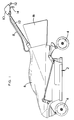
- the lawn mower comprises a cutting deck (2) mounted on four castor wheel assemblies (4).
- An electric motor (not shown) is mounted on the deck (2) and which rotatingly drives a cutting blade (not shown) mounted on the output spindle of the motor about a substantially vertical axis beneath the cutting deck (2).
- a battery (not shown) is mounted on the cutting deck which is in electrical connection with the motor via a switch mechanism (not shown) mounted on the motor. The battery powers the motor when the switch mechanism is activated.
- a hood (6) encloses the battery, motor and switch mechanism.
- a grass box (16) is attached to the rear of the mower for the collection of the grass cutting generated by the cutting action of the mower.
- a bowden cable (8) runs from the switch mechanism to a lever box (10) mounted on a handle (12) attached to the rear of the lawn mower.
- a pivotal lever (14) projects through a hole (30) in the lever box (10). Movement of the cable (18) located within the sleeve (20) of the bowden cable (8) operates the switch mechanism to complete or break the electrical circuit between the battery and motor to switch the mower on or off respectively.
- Figures 2 and 3 show the lever box (10) which comprises two plastic clamshells connected together.
- the rear handle (12) which comprises a hollow metal tube, passes through the lever box (10).
- a plurality of ribs (70) are integrally formed on the inside of both clamshells and which are shaped to receive and hold the metal tube of the handle when the clamshells are connected together.
- the two clamshells are attached to each other using three screws (72) (as shown in Figure 2), which screw into three bases (74) (shown in Figure 3).
- the ribs (70) locate the tube within the clamshells and grip the tube.
- a bend (76) within the tube is located within the lever box which co-operates with the ribs so as to prevent the lever box sliding along the tube.
- the lever (14) pivots about an axis (22).
- the sleeve (20) of the bowden cable (8) terminates in a circular flange (24) which has a diameter greater than the sleeve (20).
- the flange slots into a recess (26) formed in the clamshells and holds the flange (24) and sleeve (20) stationary relative to the lever box (10).
- the cable (18) within the bowden cable (8) is attached to the lever (14) at a point away from its axis (22) of pivot so that pivotal movement of the lever (14) results in a sliding movement of the cable (18) within the sleeve (20).
- a spring (not shown) is mounted on the switch mechanism attached to the other end of the bowden cable (8) which biases the cable (18) relative to the sleeve (20) so that, at the lever box (10) end of the bowden cable (8), the cable is biased towards being withdrawn into the sleeve (20).
- a button (28) is located on the side of the lever box (10) which can be depressed into the lever box (10). The button (28) interacts with the connection between the end of the cable (18) and the lever (14).
- FIG 4 shows a drawing of the lever (14) according to the first embodiment of the invention.
- the lever (14) comprises a grip section (32) which is located outside of the lever box (10) when assembled and which is gripped, moved and held against the biasing force of the spring by an operator when the lever is activated.
- a recess (34) having a circular cross-section and which receives a peg integrally formed with the clamshell of the lever box (10) when the lever (14) is mounted within the lever box (10) and about which the lever (14) pivots within the lever box (10).
- a second recess (36) is formed away from the first recess (34) along the lever which also has a circular cross-section.
- a slot (38) extends from the second recess (36) to the edge of the lever. The width of the slot (38) is less than the diameter of the cross-section of the second recess (36).
- the operation of the safety lock mechanism which comprises a lever according to the first embodiment of the invention will now be described with reference to Figures 5 and 8.
- the end of the cable (18) terminates in spherical metal ball (40).
- the diameter of the ball (40) is slightly less than that of the second recess (36) formed in the lever (14) but greater than the width of the slot (38) formed in the lever (14).
- the button (28) comprises an oval shaped finger engagement section (44) which is located within a corresponding oval recess (42) formed in the side of the lever box (10).
- the oval shaped finger engagement section (44) is integrally formed with a peg (46) of circular cross-section.
- the peg (46) is located in an aperture (48) having a slightly larger circular cross-section than the peg (46) but the same diameter as the second recess (36) formed in the lever (14) and which connects between the recess (42) for the finger engagement section and the inner space (50) formed by the lever box (10).
- a slot (52) of similar width to the slot (38) formed in the lever (14) extends from the side of the aperture (48). Means (not shown) prevent the button from falling out of the lever box (10).
- a spring biases the lever to a forward position as shown in Figures 5 and 6.
- Figure 5 shows the lever box when neither the lever or the button has been activated by the operator.
- the lever is in a forward position due to the biasing force of the spring.
- the second recess (36) is aligned and co-axial with the aperture (48) formed in the wall of the lever box (10).
- the slot (38) in the lever (14) is also aligned with the slot (52) in the wall of the lever box (10).
- the spherical ball (40) can be located in either the second recess (36) of the lever (14) or the aperture (48) in the wall of the lever box (10).
- the slots (38; 52) formed in the lever (14) and housing are sufficiently narrow to prevent the spherical ball from passing through the slots.
- the cable (18) attached to the spherical ball (40) is held under tension due to the biasing force of the spring on the switch mechanism mounted on the motor.
- a helical spring (54) is located within the second recess (36) of the lever (14) which engages with the bottom of the recess (36) and the spherical ball (40).
- the spring (54) biases the spherical ball into the aperture (48) which in turn presses against and biases outwardly the peg (46) of the button (28), pushing the button (28) to its outermost position.
- the cable (18) has to be pulled out of the sleeve (20) of the bowden cable (8) in the lever box (10). This is achieved by the pivotal movement of the lever (14). However, prior to pivotally moving the lever, the spherical ball (40) has to be moved so that it is engaged with the lever (14).
- the spherical ball is moved by depression of the button (28) by the operator (as shown in Figure 6). As the button (28) is depressed, the peg (46) pushes the spherical ball from the aperture (48) into the second recess (36) against the biasing force of the spring (54). When the button is fully depressed the end of the peg is aligned with the inner side of the wall of the lever box (10). The lever (14) is then pivoted about its axis of pivot (22).
- the spherical ball (40) As the lever (14) pivots, the spherical ball (40) is moved away from the sleeve (20) of the bowden cable (8), pulling the cable (18) out of the sleeve (20) against the biasing force of the spring mounted on the switch mechanism (as shown in Figure 7).
- the spherical ball (40) is prevented from being ejected from the second recess (36) due to the spring (54) by the inner side wall of the lever box (10) which is located in close proximity to the entrance to the recess (36).
- the button is able to move freely within its mount regardless of the position of the lever as it is no longer subject to the biasing force of the spring (54).
- the switch mechanism located on the motor As the cable (18) is withdrawn from the sleeve (20) the switch mechanism located on the motor is activated thus activating the mower.
- the lever is constructed in a similar manner as the first embodiment lever described previously (see Figure 4).
- the second aperture and slot in the design of the first embodiment of lever has been replaced by three apertures and corresponding slots.
- the dimensions of each of the apertures and slots are the same as the aperture and slot in the first embodiment of the lever.
- the apertures and slots are positioned radially around the axis of pivot of the lever.
- the lever is mounted in a lever box having a button and a bowden cable attached as described previously.
- the apertures are located so that, as the lever pivots, the apertures consecutively become aligned with the aperture in the lever box. This enables the lever to be pivoted to one of three angles where one of the apertures is able to receive the spherical ball, thereby setting the angular position of the lever in relation to the position of the cable of the bowden cable.
Landscapes
- Life Sciences & Earth Sciences (AREA)
- Environmental Sciences (AREA)
- Physics & Mathematics (AREA)
- General Physics & Mathematics (AREA)
- Engineering & Computer Science (AREA)
- Automation & Control Theory (AREA)
- Switches With Compound Operations (AREA)
- Harvester Elements (AREA)
- Lock And Its Accessories (AREA)
- Mechanical Control Devices (AREA)
- Push-Button Switches (AREA)
- Driving Mechanisms And Operating Circuits Of Arc-Extinguishing High-Tension Switches (AREA)
Applications Claiming Priority (2)
| Application Number | Priority Date | Filing Date | Title |
|---|---|---|---|
| GB9818787A GB2340721A (en) | 1998-08-28 | 1998-08-28 | Lever switch with safety interlock. |
| GB9818787 | 1998-08-28 |
Publications (2)
| Publication Number | Publication Date |
|---|---|
| EP0984345A1 true EP0984345A1 (de) | 2000-03-08 |
| EP0984345B1 EP0984345B1 (de) | 2001-11-21 |
Family
ID=10837981
Family Applications (2)
| Application Number | Title | Priority Date | Filing Date |
|---|---|---|---|
| EP99306538A Expired - Lifetime EP0984345B1 (de) | 1998-08-28 | 1999-08-19 | Sicherheitssperrvorrichtung für einen Hebelschalter |
| EP99306540A Expired - Lifetime EP0981945B1 (de) | 1998-08-28 | 1999-08-19 | Sicherheitssperrvorrichtung für einen Hebelschalter |
Family Applications After (1)
| Application Number | Title | Priority Date | Filing Date |
|---|---|---|---|
| EP99306540A Expired - Lifetime EP0981945B1 (de) | 1998-08-28 | 1999-08-19 | Sicherheitssperrvorrichtung für einen Hebelschalter |
Country Status (5)
| Country | Link |
|---|---|
| EP (2) | EP0984345B1 (de) |
| AT (2) | ATE220851T1 (de) |
| DE (2) | DE69900709T2 (de) |
| DK (1) | DK0984345T3 (de) |
| GB (1) | GB2340721A (de) |
Families Citing this family (6)
| Publication number | Priority date | Publication date | Assignee | Title |
|---|---|---|---|---|
| US7543430B2 (en) | 2007-09-10 | 2009-06-09 | Honda Motor Co., Ltd. | Button type blade brake clutch control |
| CN103624751B (zh) * | 2012-08-22 | 2015-12-16 | 宁波奇亚园林工具有限公司 | 一种安全手柄 |
| US9596806B2 (en) | 2013-10-10 | 2017-03-21 | Chervon (Hk) Limited | Control system for controlling the operation of a gardening tool |
| CN103959990B (zh) * | 2013-01-25 | 2016-04-13 | 天佑电器(苏州)有限公司 | 园林工具的开关控制机构 |
| US11638397B2 (en) | 2020-02-10 | 2023-05-02 | Techtronic Cordless Gp | Control assembly coupled to handle of an implement |
| CN115316107B (zh) * | 2022-07-26 | 2024-05-17 | 利欧集团浙江泵业有限公司 | 一种草坪机开关盒 |
Citations (3)
| Publication number | Priority date | Publication date | Assignee | Title |
|---|---|---|---|---|
| FR2659761A1 (fr) * | 1990-03-14 | 1991-09-20 | Nauder | Dispositif de commande d'un organe d'une machine. |
| WO1993014621A1 (en) | 1992-01-22 | 1993-08-05 | Ryobi Motor Products Corporation | Lawn mower activation switch |
| DE4228103C1 (de) * | 1992-08-28 | 1993-12-09 | Sabo Maschf | Betätigungsvorrichtung für eine Schalteinrichtung an einem Gerät zur Garten-, Rasen- oder Landschaftspflege |
Family Cites Families (9)
| Publication number | Priority date | Publication date | Assignee | Title |
|---|---|---|---|---|
| US3459374A (en) * | 1965-07-07 | 1969-08-05 | Ransburg Electro Coating Corp | Electrostatic coating apparatus |
| EP0047416B2 (de) * | 1980-09-04 | 1988-07-27 | Wolf-Geräte GmbH | Sicherheitsschaltvorrichtung für einen Elektrorasenmäher |
| US4413466A (en) * | 1982-01-01 | 1983-11-08 | Conchemco, Incorporated | Control assembly for blade clutch unit |
| DE3302544A1 (de) * | 1983-01-26 | 1984-07-26 | Wolf-Geräte GmbH, 5240 Betzdorf | Elektromaeher mit radantrieb |
| DE3827926A1 (de) * | 1988-08-17 | 1990-02-22 | Gardena Kress & Kastner Gmbh | Einschaltvorrichtung fuer elektrisch betriebene gartengeraete oder dgl. |
| GB2246021B (en) * | 1990-06-18 | 1994-05-04 | Qualcast Garden Prod | Actuating mechanisms |
| EP0704368B1 (de) * | 1994-09-29 | 2000-02-23 | Starting Industrial Co., Ltd. | Verdrehsicherung für Betätigungshebel und Entriegelungsmechanik für einen Hebel |
| DE19544279C1 (de) * | 1995-11-28 | 1997-01-16 | Schulte Elektrotech | Elektrischer Schalter |
| JP3329654B2 (ja) * | 1996-03-22 | 2002-09-30 | 株式会社マキタ | 電動芝刈機の操作スイッチ |
-
1998
- 1998-08-28 GB GB9818787A patent/GB2340721A/en not_active Withdrawn
-
1999
- 1999-08-19 AT AT99306540T patent/ATE220851T1/de not_active IP Right Cessation
- 1999-08-19 DK DK99306538T patent/DK0984345T3/da active
- 1999-08-19 DE DE69900709T patent/DE69900709T2/de not_active Expired - Lifetime
- 1999-08-19 EP EP99306538A patent/EP0984345B1/de not_active Expired - Lifetime
- 1999-08-19 EP EP99306540A patent/EP0981945B1/de not_active Expired - Lifetime
- 1999-08-19 AT AT99306538T patent/ATE209372T1/de not_active IP Right Cessation
- 1999-08-19 DE DE69902211T patent/DE69902211T2/de not_active Expired - Fee Related
Patent Citations (3)
| Publication number | Priority date | Publication date | Assignee | Title |
|---|---|---|---|---|
| FR2659761A1 (fr) * | 1990-03-14 | 1991-09-20 | Nauder | Dispositif de commande d'un organe d'une machine. |
| WO1993014621A1 (en) | 1992-01-22 | 1993-08-05 | Ryobi Motor Products Corporation | Lawn mower activation switch |
| DE4228103C1 (de) * | 1992-08-28 | 1993-12-09 | Sabo Maschf | Betätigungsvorrichtung für eine Schalteinrichtung an einem Gerät zur Garten-, Rasen- oder Landschaftspflege |
Also Published As
| Publication number | Publication date |
|---|---|
| ATE220851T1 (de) | 2002-08-15 |
| EP0984345B1 (de) | 2001-11-21 |
| GB2340721A (en) | 2000-03-01 |
| DE69900709T2 (de) | 2002-05-08 |
| EP0981945B1 (de) | 2002-07-24 |
| EP0981945A2 (de) | 2000-03-01 |
| ATE209372T1 (de) | 2001-12-15 |
| DE69902211T2 (de) | 2003-03-27 |
| DK0984345T3 (da) | 2002-05-21 |
| EP0981945A3 (de) | 2000-08-09 |
| GB9818787D0 (en) | 1998-10-21 |
| DE69902211D1 (de) | 2002-08-29 |
| DE69900709D1 (de) | 2002-02-21 |
Similar Documents
| Publication | Publication Date | Title |
|---|---|---|
| US9175756B2 (en) | Speed control assembly for a self-propelled walk behind lawn mower | |
| EP1864564B1 (de) | Vorrichtung und Verfahren zur Steuerung einer Übertragungsdrehung mit variabler Drehzahl für eine selbstangetriebene Mähmaschine | |
| EP3515169B1 (de) | Steueranordnung für einen handgeführten mäher | |
| US5685080A (en) | Battery powered chain saw | |
| EP2777377B1 (de) | Türheber und griff für handgeführten mäher | |
| US6550161B2 (en) | Walk behind self-propelled crawler snowplow | |
| US4531347A (en) | Lawn mower with wheel drive | |
| EP0984345B1 (de) | Sicherheitssperrvorrichtung für einen Hebelschalter | |
| US7240756B2 (en) | Method of operator presence control on walk behind powered equipment | |
| JPH05344816A (ja) | 芝刈り機ハンドル組立体 | |
| US11452258B2 (en) | Grass trimmer | |
| EP1457103B1 (de) | Drosselklappe | |
| AU2020100022A4 (en) | Grass trimmer | |
| EP4096386B1 (de) | Schneidwerkzeug | |
| JP5277678B2 (ja) | 芝刈機 | |
| JPH0840A (ja) | 歩行型芝刈機の操作レバー保持装置 | |
| JPH01144108A (ja) | 歩行型芝刈り機のクラッチ操作構造 | |
| CA2171510A1 (en) | Electric mower switch | |
| JPH09109718A (ja) | 移動農機の走行レバーガイド |
Legal Events
| Date | Code | Title | Description |
|---|---|---|---|
| PUAI | Public reference made under article 153(3) epc to a published international application that has entered the european phase |
Free format text: ORIGINAL CODE: 0009012 |
|
| AK | Designated contracting states |
Kind code of ref document: A1 Designated state(s): AT BE CH CY DE DK ES FI FR GB GR IE IT LI LU MC NL PT SE |
|
| AX | Request for extension of the european patent |
Free format text: AL;LT;LV;MK;RO;SI |
|
| 17P | Request for examination filed |
Effective date: 20000417 |
|
| 17Q | First examination report despatched |
Effective date: 20000925 |
|
| AKX | Designation fees paid |
Free format text: AT BE CH CY DE DK ES FI FR GB GR IE IT LI LU MC NL PT SE |
|
| RIC1 | Information provided on ipc code assigned before grant |
Free format text: 7G 05G 5/00 A, 7A 01D 34/68 B |
|
| RTI1 | Title (correction) |
Free format text: SAFETY LOCK MECHANISM FOR A LEVER SWITCH |
|
| GRAG | Despatch of communication of intention to grant |
Free format text: ORIGINAL CODE: EPIDOS AGRA |
|
| GRAG | Despatch of communication of intention to grant |
Free format text: ORIGINAL CODE: EPIDOS AGRA |
|
| GRAH | Despatch of communication of intention to grant a patent |
Free format text: ORIGINAL CODE: EPIDOS IGRA |
|
| GRAH | Despatch of communication of intention to grant a patent |
Free format text: ORIGINAL CODE: EPIDOS IGRA |
|
| GRAA | (expected) grant |
Free format text: ORIGINAL CODE: 0009210 |
|
| AK | Designated contracting states |
Kind code of ref document: B1 Designated state(s): AT BE CH CY DE DK ES FI FR GB GR IE IT LI LU MC NL PT SE |
|
| PG25 | Lapsed in a contracting state [announced via postgrant information from national office to epo] |
Ref country code: LI Free format text: LAPSE BECAUSE OF FAILURE TO SUBMIT A TRANSLATION OF THE DESCRIPTION OR TO PAY THE FEE WITHIN THE PRESCRIBED TIME-LIMIT Effective date: 20011121 Ref country code: GR Free format text: LAPSE BECAUSE OF FAILURE TO SUBMIT A TRANSLATION OF THE DESCRIPTION OR TO PAY THE FEE WITHIN THE PRESCRIBED TIME-LIMIT Effective date: 20011121 Ref country code: CH Free format text: LAPSE BECAUSE OF FAILURE TO SUBMIT A TRANSLATION OF THE DESCRIPTION OR TO PAY THE FEE WITHIN THE PRESCRIBED TIME-LIMIT Effective date: 20011121 Ref country code: AT Free format text: LAPSE BECAUSE OF FAILURE TO SUBMIT A TRANSLATION OF THE DESCRIPTION OR TO PAY THE FEE WITHIN THE PRESCRIBED TIME-LIMIT Effective date: 20011121 |
|
| REF | Corresponds to: |
Ref document number: 209372 Country of ref document: AT Date of ref document: 20011215 Kind code of ref document: T |
|
| REG | Reference to a national code |
Ref country code: CH Ref legal event code: EP |
|
| REG | Reference to a national code |
Ref country code: IE Ref legal event code: FG4D |
|
| REG | Reference to a national code |
Ref country code: GB Ref legal event code: IF02 |
|
| PG25 | Lapsed in a contracting state [announced via postgrant information from national office to epo] |
Ref country code: PT Free format text: LAPSE BECAUSE OF FAILURE TO SUBMIT A TRANSLATION OF THE DESCRIPTION OR TO PAY THE FEE WITHIN THE PRESCRIBED TIME-LIMIT Effective date: 20020221 |
|
| REF | Corresponds to: |
Ref document number: 69900709 Country of ref document: DE Date of ref document: 20020221 |
|
| REG | Reference to a national code |
Ref country code: DK Ref legal event code: T3 |
|
| PG25 | Lapsed in a contracting state [announced via postgrant information from national office to epo] |
Ref country code: ES Free format text: LAPSE BECAUSE OF FAILURE TO SUBMIT A TRANSLATION OF THE DESCRIPTION OR TO PAY THE FEE WITHIN THE PRESCRIBED TIME-LIMIT Effective date: 20020530 |
|
| REG | Reference to a national code |
Ref country code: CH Ref legal event code: PL |
|
| PG25 | Lapsed in a contracting state [announced via postgrant information from national office to epo] |
Ref country code: LU Free format text: LAPSE BECAUSE OF NON-PAYMENT OF DUE FEES Effective date: 20020819 Ref country code: IE Free format text: LAPSE BECAUSE OF NON-PAYMENT OF DUE FEES Effective date: 20020819 |
|
| PG25 | Lapsed in a contracting state [announced via postgrant information from national office to epo] |
Ref country code: CY Free format text: LAPSE BECAUSE OF FAILURE TO SUBMIT A TRANSLATION OF THE DESCRIPTION OR TO PAY THE FEE WITHIN THE PRESCRIBED TIME-LIMIT Effective date: 20020831 |
|
| PLBE | No opposition filed within time limit |
Free format text: ORIGINAL CODE: 0009261 |
|
| STAA | Information on the status of an ep patent application or granted ep patent |
Free format text: STATUS: NO OPPOSITION FILED WITHIN TIME LIMIT |
|
| 26N | No opposition filed | ||
| PG25 | Lapsed in a contracting state [announced via postgrant information from national office to epo] |
Ref country code: MC Free format text: LAPSE BECAUSE OF NON-PAYMENT OF DUE FEES Effective date: 20030301 |
|
| REG | Reference to a national code |
Ref country code: IE Ref legal event code: MM4A |
|
| PGFP | Annual fee paid to national office [announced via postgrant information from national office to epo] |
Ref country code: NL Payment date: 20030801 Year of fee payment: 5 |
|
| PGFP | Annual fee paid to national office [announced via postgrant information from national office to epo] |
Ref country code: SE Payment date: 20030821 Year of fee payment: 5 |
|
| PGFP | Annual fee paid to national office [announced via postgrant information from national office to epo] |
Ref country code: FI Payment date: 20030822 Year of fee payment: 5 Ref country code: DK Payment date: 20030822 Year of fee payment: 5 |
|
| PGFP | Annual fee paid to national office [announced via postgrant information from national office to epo] |
Ref country code: BE Payment date: 20030911 Year of fee payment: 5 |
|
| PG25 | Lapsed in a contracting state [announced via postgrant information from national office to epo] |
Ref country code: FI Free format text: LAPSE BECAUSE OF NON-PAYMENT OF DUE FEES Effective date: 20040819 |
|
| PG25 | Lapsed in a contracting state [announced via postgrant information from national office to epo] |
Ref country code: SE Free format text: LAPSE BECAUSE OF NON-PAYMENT OF DUE FEES Effective date: 20040820 |
|
| PG25 | Lapsed in a contracting state [announced via postgrant information from national office to epo] |
Ref country code: DK Free format text: LAPSE BECAUSE OF NON-PAYMENT OF DUE FEES Effective date: 20040831 Ref country code: BE Free format text: LAPSE BECAUSE OF NON-PAYMENT OF DUE FEES Effective date: 20040831 |
|
| BERE | Be: lapsed |
Owner name: *BLACK & DECKER INC. Effective date: 20040831 |
|
| PG25 | Lapsed in a contracting state [announced via postgrant information from national office to epo] |
Ref country code: NL Free format text: LAPSE BECAUSE OF NON-PAYMENT OF DUE FEES Effective date: 20050301 |
|
| EUG | Se: european patent has lapsed | ||
| NLV4 | Nl: lapsed or anulled due to non-payment of the annual fee |
Effective date: 20050301 |
|
| REG | Reference to a national code |
Ref country code: DK Ref legal event code: EBP |
|
| PG25 | Lapsed in a contracting state [announced via postgrant information from national office to epo] |
Ref country code: IT Free format text: LAPSE BECAUSE OF NON-PAYMENT OF DUE FEES Effective date: 20050819 |
|
| BERE | Be: lapsed |
Owner name: *BLACK & DECKER INC. Effective date: 20040831 |
|
| PGFP | Annual fee paid to national office [announced via postgrant information from national office to epo] |
Ref country code: GB Payment date: 20120828 Year of fee payment: 14 |
|
| PGFP | Annual fee paid to national office [announced via postgrant information from national office to epo] |
Ref country code: DE Payment date: 20120829 Year of fee payment: 14 Ref country code: FR Payment date: 20120830 Year of fee payment: 14 |
|
| GBPC | Gb: european patent ceased through non-payment of renewal fee |
Effective date: 20130819 |
|
| PG25 | Lapsed in a contracting state [announced via postgrant information from national office to epo] |
Ref country code: DE Free format text: LAPSE BECAUSE OF NON-PAYMENT OF DUE FEES Effective date: 20140301 |
|
| REG | Reference to a national code |
Ref country code: DE Ref legal event code: R119 Ref document number: 69900709 Country of ref document: DE Effective date: 20140301 |
|
| REG | Reference to a national code |
Ref country code: FR Ref legal event code: ST Effective date: 20140430 |
|
| PG25 | Lapsed in a contracting state [announced via postgrant information from national office to epo] |
Ref country code: GB Free format text: LAPSE BECAUSE OF NON-PAYMENT OF DUE FEES Effective date: 20130819 |
|
| PG25 | Lapsed in a contracting state [announced via postgrant information from national office to epo] |
Ref country code: FR Free format text: LAPSE BECAUSE OF NON-PAYMENT OF DUE FEES Effective date: 20130902 |