EP0983935B1 - Unter Wasser ausgesetzte, akustische Warneinheit - Google Patents
Unter Wasser ausgesetzte, akustische Warneinheit Download PDFInfo
- Publication number
- EP0983935B1 EP0983935B1 EP99306873A EP99306873A EP0983935B1 EP 0983935 B1 EP0983935 B1 EP 0983935B1 EP 99306873 A EP99306873 A EP 99306873A EP 99306873 A EP99306873 A EP 99306873A EP 0983935 B1 EP0983935 B1 EP 0983935B1
- Authority
- EP
- European Patent Office
- Prior art keywords
- acoustic
- underwater vehicle
- helicopter
- acoustosensitive
- assembly
- Prior art date
- Legal status (The legal status is an assumption and is not a legal conclusion. Google has not performed a legal analysis and makes no representation as to the accuracy of the status listed.)
- Expired - Lifetime
Links
Images




Classifications
-
- B—PERFORMING OPERATIONS; TRANSPORTING
- B63—SHIPS OR OTHER WATERBORNE VESSELS; RELATED EQUIPMENT
- B63G—OFFENSIVE OR DEFENSIVE ARRANGEMENTS ON VESSELS; MINE-LAYING; MINE-SWEEPING; SUBMARINES; AIRCRAFT CARRIERS
- B63G8/00—Underwater vessels, e.g. submarines; Equipment specially adapted therefor
- B63G8/39—Arrangements of sonic watch equipment, e.g. low-frequency, sonar
-
- G—PHYSICS
- G01—MEASURING; TESTING
- G01V—GEOPHYSICS; GRAVITATIONAL MEASUREMENTS; DETECTING MASSES OR OBJECTS; TAGS
- G01V1/00—Seismology; Seismic or acoustic prospecting or detecting
- G01V1/001—Acoustic presence detection
Definitions
- the present invention relates to an acoustic warning assembly and, more particularly, to an acoustic warning assembly capable of being launched from an underwater vehicle, such as a submarine.
- a submarine while being relatively protected when submerged, is exposed to attacks when surfaced. Such attacks are in many cases launched by helicopters equipped with missiles capable of penetrating the submarine's outer shell and severely damage and/or drawn the underwater vehicle.
- an acoustic warning assembly capable of being launched from an underwater vehicle, because such an assembly would enable submarines to detect above-surface helicopters while remaining submerged and undetected thereby.
- US-A-4719606 teaches a method and device for passive detection of helicopters, the method including: detection of helicopter noise and ambient noise by means of an electro-acoustic transducer, and outputting of an amplitude modulated signal therefrom; amplitude demodulation of the signal in the frequency band between 300 Hz and 3500 Hz; spectral analysis of the demodulated signal; and selection and registration of characteristic frequency lines reflective of the rotary units of the helicopter.
- the process and device permit passive detection of helicopters in the lower noise, higher frequency band, thereby also permitting utilization of smaller antenna arrays.
- Andrieu teaches a method of analyzing above-surface acoustic signals for detecting the presence of a helicopter, by means of an analyzer having an acoustic signal frequency identifying algorithm.
- Andrieu does not disclose or suggest detecting the presence of a helicopter by sweeping a frequency spectrum of acoustic signals for harmonic patters, nor does Andrieu disclose or suggest an analyzer having a detection algorithm that utilizes such harmonic patterns in detecting a helicopter.
- an acoustic system for detection and identification of a helicopter, from a submerged underwater vehicle comprising:
- a method of detecting, from a submerged underwater vehicle, a presence of a helicopter comprising the steps of:
- the communication medium includes at least one communication wire.
- the acoustic warning assembly may further comprise a lifting body releasably engaged within the carrier member, the lifting body being connected to the underwater vehicle via a tether.
- the at least one communication medium may include a deployable wire communicating between the acoustosensitive member and the lifting body, whereby the tether serves for communicating between the lifting body and the underwater vehicle.
- the acoustic warning assembly may include (i) a releasable protective cover engaged at a front end thereof; and (ii) a pressure sensitive mechanism for releasing the protective cover when the front end of the carrier member is above surface.
- the acoustic warning assembly may include a drag inducing mechanism for slowing its migration towards the water surface after launching.
- the acoustosensitive member may include a windshield for shielding the acoustosensitive member from wind.
- the acoustic warning assembly may include an ejecting mechanism engaged therein for ejecting the acoustosensitive member.
- the acoustic warning assembly may include a self destruction mechanism.
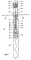
- Figures 1-7 illustrate the various aspects of the acoustic warning assembly according to the present invention, which is referred to hereinbelow as assembly 20 .
- assembly 20 is capable of being launched from an underwater vehicle 21 (shown in Figure 7), such as a submarine, and maintain communication with underwater vehicle 21 for alerting underwater vehicle 21 while the latter is submerged deep (eg 80 meters) underwater.
- an underwater vehicle 21 shown in Figure 7
- underwater vehicle 21 such as a submarine
- acoustic warning assembly 20 includes an acoustosensitive member 22 .
- Member 22 serves for collecting above-surface (above-water, air) acoustic signals.
- Member 22 can be any device capable of transforming sound waves into changes in electric current, resistance, charge, voltage or resistance, such as, but not limited to, a microphone. Laser based microphones are also applicable.
- acoustosensitive member 22 is protected by a windshield 25 , for shielding acoustosensitive member 22 for wind associated acoustic signals.
- Acoustic warning assembly 20 further includes a carrier member 24 .
- Member 24 is designed to be launched from underwater vehicle 21 and to carry acoustosensitive member 22 above-surface, where it is operable.
- acoustic warning assembly 20 further includes a communication medium 26 .
- Medium 26 serves for communicating between acoustosensitive member 22 and underwater vehicle 21 , for transmitting the above-surface acoustic signals collected thereby to underwater vehicle 21 .
- communication medium 26 includes at least one deployable (eg spooled) communication wire, seen deployed in Figures 3-6.
- deployable communication wire seen deployed in Figures 3-6.
- wireless communication media such as, but not limited to, in-water acoustic communication, etc., are also within the scope of the present invention.
- US Pat. Nos. 5,046,359, and 5,191,790 teach assemblies capable of being launched from a submarine to carry into seawater an element responsive to a property of the water to be measured.
- the disclosed assemblies comprising a carrier member coupled to the element, a lifting body shaped to provide hydrodynamic lift, a tether for mechanically connecting the lifting body to the submarine, the lifting body and the tether being constructed and arranged so that the lifting body, when connected to a moving submarine, will move through the water at a distance above the submarine, a supply of electrically conductive cable connected to the element and stored at least in part by the lifting body for payout to accommodate movement of the submarine relative to the member, and releasable coupling means for holding the member and the lifting body together during their launch from the submarine and thereafter releasing the lifting body from the member.
- These patents also teach how to launch the carrier member from a submarine.
- acoustic warning assembly 20 further includes a lifting body 28 ( Figures 1-2 and 7).
- Body 28 is releasably engaged within carrier member 24 .
- a deployable tether 29 connects body 28 and underwater vehicle 21 .
- Tether 29 is preferably rolled around body 28 prior to deployment and is selected strong enough to withstand drag forced inflicted thereupon when vehicle 21 locomotes and pulls body 28 via tether 29 .
- tether 29 further serves for communicating between body 28 and vehicle 21 . In this respect it forms a part of communication medium 26.
- the release of lifting body 28 from member 24 after launch is effected, according to a preferred embodiment of the invention, by having a rear cover 31 (shown in Figures 1-2) of member 24 removed prior to launch, and entrance of seawater into member 24 via ventilation openings 32 while progressing to surface after launch.
- a rear cover 31 shown in Figures 1-2
- it is effected essentially as described in U.S. Pat. Nos. 5,046,359, and 5,191,790 via a releasable coupling mechanism, for holding lifting body 28 within carrier member 24 during their launch from the underwater vehicle and thereafter releasing the lifting body from member 24 .
- communication medium 26 includes a deployable wire 26a .
- Wire 26a is spooled at one end thereof on a first spool 30 engaged within member 24 and at the other end thereof on a second spool 33 engaged within body 28 .
- Wire 26a serves for communicating between acoustosensitive member 22 and lifting body 28
- tether 29 serves for communicating between body 28 and vehicle 21 .
- This arrangement enables to efficiently deploy wire 26a and ensures that minimal drag forces act of wire 26a , even when underwater vehicle 21 locomotes and drags body 28 therebehind.
- Lifting body 28 serves to keep communication wire 26a and tether 29 away from propellers 23 of underwater vehicle 21 when medium 26 is deployed.
- carrier member 24 includes a releasable protective cover 34 ( Figures 1-4) engaged at a front end thereof, and a pressure sensitive mechanism 36 for releasing (e.g., eventually detaching) protective cover 34 when the front end of carrier member 24 is above surface.
- Cover 34 protects member 22 from hydrostatic pressure while underwater, such that a water resistant, yet pressure sensitive member 22 can be employed at lower costs. It is released and preferably dropped to the water when assembly 20 surfaces, as further detailed hereinunder. If so required, cover 34 may further protect windshield 25 from becoming soaked with water which may alter its acoustic properties. However, according to a preferred embodiment of the present invention windshield 25 is selected such that after being soaked it quickly releases water load therefrom.
- pressure sensitive mechanism 36 serves additional functions, its construction and operation will be described in the following sections.
- carrier member 24 includes a drag inducing mechanism 38 .
- Mechanism 38 preferably includes fin-like elements which are connected through deploying mechanisms 27 to assembly 20 , are deployable after launch, and serve for slowing the migration of assembly 20 towards the water surface after launching, such that assembly 20 will not eject abruptly above water surface upon surfacing.
- deploying drag inducing mechanism 38 is preferably controlled by pressure sensitive mechanism 36 .
- carrier assembly 20 includes an ejecting mechanism engaged therein for ejecting acoustosensitive member 22 when surfaced.
- the ejecting mechanism is preferably effected by pressure sensitive mechanism 36 .
- Sensitive pressure mechanism 36 includes a cylindrical envelope 40 engaging a front plunger 42 , a rear halter 44 and a spring 46 therebetween.
- a rod 48 connects front plunger 42 and a translatable platform 45 which engages acoustosensitive member 22 and which is capable when translated to push away cover 34 .
- the ability of spring 46 to extent is restricted by the hydrostatic pressure imposed on cover 34 . This restriction is gradually reduced as assembly 20 progresses toward the surface.
- mechanism 36 further includes a dampening arrangement 37 which includes a narrow radial gap 39 formed between envelope 40 and plunger 42 .
- translatable platform 45 When translatable platform 45 is translated in a frontal direction, it pushes away cover 34 .
- Cover 34 is engaged to a lower ring 50 which holds the distal ends of the fin-like elements of mechanism 38 .
- mechanism 38 is released and deployed, thereby slowing the migration of assembly 20 to the surface.
- Dampening arrangement 37 is designed such that it is inoperative in the last two stages, i.e., detaching cover 34 and fully ejecting member 20 . This is achieved by limiting the region in which gap 39 is narrow, and following this narrow gap region with a wider gap region 41 , for allowing free plunger movement.
- Sensitive pressure mechanism 36 further includes oil compensation system 52 for compensating for volume and temperature changes of dampening arrangement 37 .
- a passively extendible accordion like seal 53 engaged at one end thereof to platform 45 and at another end thereof to the body of member 24 is preferably employed to prevent water from entering member 24 , since water within member 24 will hamper its specific weight and its weight distribution.
- the specific weight of, and the weight distribution within, assembly 20 , spring's 46 constant, the effectiveness of and duration of operation of dampening arrangement 37 and of drag inducing mechanism 38 , and the specific construction of the various parts described are preferably selected such that (i) the fin-like elements of mechanism 38 are deployed when assembly 20 is about 9 meters under surface; (ii) when at surface level, now deployed fin-like elements of mechanism 38 are substantially at surface level, such that only a frontal quarter of assembly 20 protrudes from the water surface; (iii) the detachment of cover 34 and the full erection of acoustosensitive member 22 are achieved only after assembly 22 has settled at the surface.
- mechanism 36 may replace mechanism 36 , to otherwise similarly perform.
- Assembly 20 includes a cover holder 60 for holding cover 34 at place under atmospheric pressure prior to launch ( Figures 1-2).
- Cover holder 60 includes a safety pin 62 which is removed prior to launch by the launch crew and a safety ring 64 which is removed during launch by the launching port of underwater vehicle 21 . The latter is removed only after assembly 20 is subjected to the hydrostatic pressure outside vehicle 21 , such that cover 34 is now held in place by the pressure.
- assembly 20 includes a self destruction mechanism 70 .
- Mechanism 70 preferably includes a detonator and explosives.
- the detonator is controlled by a timer and/or chip-on-board and is powered via a power source, e.g., a lithium battery and power conditioning electronics.
- the same or another power source and dedicated electronics are used to power and control the operation of acoustosensitive member 22 .
- the dedicated electronics is triggered to operate by the switch that is operated by pressure sensitive mechanism 36 .
- the electronics can also include a recording mechanism to record and store the signals collected by member 22 for delayed retrieval by underwater vehicle 21 . Self destruction may be time preset or controlled from vehicle 21 via communication medium 26 .
- the present invention provides a method of detecting a presence or absence of an airborne vehicle, namely a helicopter, from a submerged underwater vehicle.
- the method is performed by executing the following method steps in which in a first step an acoustic warning assembly is launched from the submerged underwater vehicle, the acoustic warning assembly includes an acoustosensitive member for collecting above-surface acoustic signals.
- a communication is established between the submerged underwater vehicle and acoustic warning assembly for receiving above-surface acoustic signals.
- above-surface acoustic signals are analyzed for detecting the presence or absence of the helicopter. Analysis may be performed manually by simply listening to the noises, or electronically as further detailed hereinunder. A well trained listener will be able in most cases to identify the type of helicopter detected.
- the present invention also provides a method of identifying an airborne vehicle, namely a helicopter, from a submerged underwater vehicle.
- the method is performed by executing the following method steps in which in a first step an acoustic warning assembly is launched from the submerged underwater vehicle, the acoustic warning assembly including an acoustosensitive member for collecting above-surface acoustic signals.
- a communication is established between the submerged underwater vehicle and acoustic warning assembly for receiving above-surface acoustic signals.
- an acoustic signal frequency identifying algorithm capable of differentiating among types of helicopters according to their acoustic signature is used for analyzing above-surface acoustic signals, to thereby identify the helicopter.
- the present invention further provides an acoustic system for detecting a presence or absence of an airborne vehicle, namely a helicopter, from a submerged underwater vehicle.
- the system includes an acoustic warning assembly capable of being launched from an underwater vehicle while submerged underwater, the acoustic warning assembly includes (i) an acoustosensitive member for collecting above-surface acoustic signals; (ii) a carrier member being launchable from the underwater vehicle, the carrier member is designed to carry acoustosensitive member above-surface; and (iii) a communication medium for communicating between the acoustosensitive member and the underwater vehicle, for transmitting above-surface acoustic signals being collected by acoustosensitive member to underwater vehicle.
- the system further includes an analyzer installed in the underwater vehicle for receiving above-surface acoustic signals via the communication medium and for analyzing the above-surface acoustic signals, for detecting the presence or absence of the helicopter.
- the analyzer may include an acoustic signal frequency identifying algorithm capable of differentiating among types of airborne vehicles according to their acoustic signature. The algorithm is employed for analyzing above-surface acoustic signals and thereby for identifying the type of the airborne vehicle.
- a helicopter When a helicopter is within detection and identification range of acoustosensitive member 22 , its associated acoustic signal or signature is picked-up by member 22 . As indicated by box 80 , this data signal is filtered and amplified by a conditioning network which also generates a test signal. Both signals are combined and sent to the underwater vehicle via wire 26 .
- a signal processing unit installed in the underwater vehicle collects the combined signal and digitizes it.
- the test and data signals are hen each filtered out from the combined signal and the test signal is identified to verify proper operation of system.
- a display processing system conditions the filtered data signal for presentation on a main display, which is indicated by box 85 , which enables the operator to supervise system operation and also detect and identify targets manually, if so desired and in case of insufficient signal-to-noise ratio for automatic detection and identification as further detailed hereinunder, or in case of insufficient data.
- a tonal detection system actuates tone detection algorithms to facilitate automatic detection and identification of targets.
- a suitable tone detection algorithm can, for example, include a fast Fourier transform (FFT) algorithm for spectral analysis.
- FFT fast Fourier transform
- a harmonic pattern detector sweeps the frequency spectrum of the signal for harmonic patterns, which are counted.
- each record therein includes a helicopter type field, main rotor frequency field and a tail rotor/main rotor frequency ratio field. These two latter constants are sufficient to uniquely identify a helicopter type.
- each library entry is Doppler adjusted to compensate for helicopter approach velocity.
- main rotor harmonic patterns and tail rotor harmonic patterns are calculated and compared, as indicated by 98 , to the detected data signal.
- an identification signal is displayed including the helicopter name, ammunition, etc., as retrieved from the library record.
- N1, N2, and N3 are each independently an integer greater than 1, typically in a range of 2-50, typically 2-4, and are used to optimize the analyzer or the detection and identification system described herein.
Landscapes
- Engineering & Computer Science (AREA)
- Physics & Mathematics (AREA)
- Acoustics & Sound (AREA)
- Life Sciences & Earth Sciences (AREA)
- Remote Sensing (AREA)
- Geology (AREA)
- Environmental & Geological Engineering (AREA)
- General Life Sciences & Earth Sciences (AREA)
- General Physics & Mathematics (AREA)
- Geophysics (AREA)
- Radar, Positioning & Navigation (AREA)
- Mechanical Engineering (AREA)
- Aviation & Aerospace Engineering (AREA)
- Measurement Of Velocity Or Position Using Acoustic Or Ultrasonic Waves (AREA)
- Measurement Of Mechanical Vibrations Or Ultrasonic Waves (AREA)
Claims (10)
- Verfahren zur Erfassung, von einem untergetauchten Unterwasserfahrzeug (21) aus, einer Anwesenheit eines Hubschraubers, wobei das Verfahren die folgenden Schritte umfasst:a) aus dem untergetauchten Unterwasserfahrzeug (21) Aussetzen eines akustischen Geräts (20), das ein akustisch sensitives Teil (22) zur Sammlung von akustischen Überwassersignalen enthält;b) Herstellen einer Kommunikation zwischen dem untergetauchten Unterwasserfahrzeug (21) und dem akustischen Gerät (20) zum Empfang der akustischen Überwassersignale, undc) Analysieren der akustischen Überwassersignale zur Erfassung der Anwesenheit des Hubschraubers, mittels eines eine akustische Signalfrequenz identifizierenden Algorithmus,dadurch gekennzeichnet, dass das Analysieren mittels des die akustische Signalfrequenz identifizierenden Algorithmus weiterhin beinhaltet:Erfassen der Anwesenheit des Hubschraubers durch Abtasten eines Frequenzspektrums der akustischen Signale nach harmonischen Mustern.
- Verfahren nach Anspruch 1, wobei die harmonischen Muster ein harmonisches Hauptrotormuster und ein harmonisches Heckrotormuster enthalten.
- Verfahren nach Anspruch 1, wobei, wenn mehr als eine vorgegebene Anzahl der harmonischen Muster gezählt wird, ein Erfassungssignal ausgegeben wird.
- Verfahren nach Anspruch 1, wobei eine Identifizierung eines bestimmten Hubschraubertyps geleistet wird durch:i) Erfassen eines harmonischen Hauptrotormusters und eines harmonischen Heckrotormusters, undii) Vergleichen der Muster mit gespeicherten Aufzeichnungen, die ein Feld haben, das ein Verhältnis von Heckrotorfrequenz zu Hauptrotorfrequenz enthält.
- Verfahren nach Anspruch 4, wobei, wenn mehr als eine erste vorgegebene Anzahl harmonischer Hauptrotormuster und mehr als eine zweite vorgegebene Anzahl harmonischer Heckrotormuster erfasst werden, das Verfahren weiterhin den folgenden Schritt umfasst:d) Ausgeben eines Identifizierungssignals, welches eine Identität des jeweiligen Hubschraubertyps anzeigt.
- Akustisches System zur Erfassung und Identifizierung eines Hubschraubers, von einem untergetauchten Unterwasserfahrzeug aus, wobei dieses System Folgendes aufweist:(a) ein akustisches Gerät (20), das aus einem Unterwasserfahrzeug (21) ausgesetzt werden kann, während dieses unter Wasser ist, wobei das akustische Gerät (20) Folgendes enthält:i) ein akustisch sensitives Teil (22) zum Sammeln einer Sammlung akustischer Überwassersignale;ii) ein Trägerteil (24), das aus dem Unterwasserfahrzeug (21) ausgesetzt werden kann, wobei das Trägerteil (24) in der Lage ist, das akustisch sensitive Teil (22) über Wasser zu tragen; undiii) ein Kommunikationsmedium (26) zur Kommunikation zwischen dem akustisch sensitiven Teil (22) und dem Unterwasserfahrzeug (21), zwecks Übertragung der Sammlung akustischer Überwassersignale an das Unterwasserfahrzeug (21);b) eine Analyseeinheit, angebracht in dem Unterwasserfahrzeug (21), zum Empfang der Sammlung akustischer Überwassersignale via das Kommunikationsmedium (26) und zur Analyse der Sammlung, undc) einen eine akustische Signalfrequenz identifizierenden Algorithmus (88), der zu der Analyseeinheit gehört,wobei das akustische System dadurch gekennzeichnet ist, dass der die akustische Signalfrequenz identifizierende Algorithmus (88) weiterhin umfasst:einen Erfassungsalgorithmus zur Erfassung einer Anwesenheit einer Mehrzahl harmonischer Muster, um den Hubschrauber zu erfassen.
- Akustisches System nach Anspruch 6, wobei der Algorithmus die Identifizierung des Hubschraubers leistet durch Analyseparameter, welche ein Verhältnis von Heckrotorfrequenz zu Hauptrotorfrequenz einschließen.
- Akustisches System nach Anspruch 7, wobei die Analyseeinheit eine Bibliothek (92) mit Aufzeichnungen zur Beurteilung durch den Erfassungsalgorithmus umfasst.
- Akustisches System nach Anspruch 8, wobei eine Mehrzahl der Aufzeichnungen ein Rotorfrequenzfeld enthält.
- Akustisches System nach Anspruch 8, wobei der Erfassungsalgorithmus die Identifizierung des Hubschraubers durch Vergleich des Verhältnisses mit den Aufzeichnungen durchführt.
Applications Claiming Priority (2)
| Application Number | Priority Date | Filing Date | Title |
|---|---|---|---|
| IL12600198 | 1998-08-31 | ||
| IL12600198A IL126001A (en) | 1998-08-31 | 1998-08-31 | Underwater launched acoustic warning assembly |
Publications (3)
| Publication Number | Publication Date |
|---|---|
| EP0983935A2 EP0983935A2 (de) | 2000-03-08 |
| EP0983935A3 EP0983935A3 (de) | 2001-11-07 |
| EP0983935B1 true EP0983935B1 (de) | 2006-07-12 |
Family
ID=11071914
Family Applications (1)
| Application Number | Title | Priority Date | Filing Date |
|---|---|---|---|
| EP99306873A Expired - Lifetime EP0983935B1 (de) | 1998-08-31 | 1999-08-27 | Unter Wasser ausgesetzte, akustische Warneinheit |
Country Status (5)
| Country | Link |
|---|---|
| US (1) | US6307810B1 (de) |
| EP (1) | EP0983935B1 (de) |
| AU (1) | AU763344B2 (de) |
| DE (1) | DE69932296D1 (de) |
| IL (1) | IL126001A (de) |
Families Citing this family (10)
| Publication number | Priority date | Publication date | Assignee | Title |
|---|---|---|---|---|
| US6883452B1 (en) | 2003-10-06 | 2005-04-26 | The United States Of America As Represented By The Secretary Of The Navy | Plunging towed array antenna |
| US7230881B2 (en) * | 2005-04-20 | 2007-06-12 | Lockheed Martin Corporation | Submarine remote surface platform |
| US8005424B2 (en) * | 2006-10-11 | 2011-08-23 | Japan Agency For Marine-Earth Science And Technology | Communication device and communication method of underwater vehicle |
| WO2008112445A1 (en) * | 2007-03-12 | 2008-09-18 | Raytheon Company | Systems and methods for detection and analysis of amplitude modulation of underwater sound |
| ES2422756T3 (es) * | 2008-03-12 | 2013-09-13 | Raytheon Co | Sistema y método de sonar autónomo |
| JP5117963B2 (ja) * | 2008-09-17 | 2013-01-16 | アークレイ株式会社 | 分析装置 |
| US8050138B2 (en) * | 2009-03-24 | 2011-11-01 | Lockheed Martin Corporation | Ballistic-acoustic transducer system |
| FR3013320B1 (fr) * | 2013-11-21 | 2017-02-10 | Dcns | Engin sous-marin equipe d'au moins une bouee munie d'un organe fonctionnel |
| FR3013318B1 (fr) * | 2013-11-21 | 2017-03-10 | Dcns | Bouee perdable de reception d'un organe fonctionnel notamment pour un engin sous-marin |
| US12044516B2 (en) | 2020-02-06 | 2024-07-23 | Austin Star Detonator Company | Integrated detonator sensors |
Family Cites Families (11)
| Publication number | Priority date | Publication date | Assignee | Title |
|---|---|---|---|---|
| US4203109A (en) * | 1964-09-28 | 1980-05-13 | Sanders Associates, Inc. | Submarine communication system |
| DE2143116C1 (de) * | 1971-08-28 | 1987-02-19 | Krupp Gmbh | |
| US5046359A (en) * | 1975-01-24 | 1991-09-10 | The Sippican Corporation | Underwater launched carrier |
| US5191790A (en) * | 1975-01-24 | 1993-03-09 | Sippican, Inc. | Carrier |
| FR2518491A1 (fr) * | 1981-12-22 | 1983-06-24 | Eca | Procede et dispositif d'observation et/ou de communication aeriennes pour sous-marin en plongee |
| FR2599860B1 (fr) * | 1984-03-22 | 1989-12-01 | France Etat Armement | Procede et dispositif pour la detection acoustique passive d'aeronefs, notamment d'helicopteres |
| US4794575A (en) * | 1987-10-02 | 1988-12-27 | The United States Of America As Represented By The Secretary Of The Navy | Submarine launched sea-state buoy (SLSSB) |
| US5060206A (en) * | 1990-09-25 | 1991-10-22 | Allied-Signal Inc. | Marine acoustic aerobuoy and method of operation |
| DE4440150C2 (de) * | 1994-11-10 | 1997-05-15 | Bundesrep Deutschland | Aufklärungsfahrzeug für Uboote |
| US5721712A (en) * | 1996-08-05 | 1998-02-24 | The United States Of America As Represented By The Secretary Of The Navy | Aircraft detection system |
| US5951346A (en) * | 1997-12-08 | 1999-09-14 | The United States Of America As Represented By The Secretary Of The Navy | Air-delivered position marking device and method |
-
1998
- 1998-08-31 IL IL12600198A patent/IL126001A/xx not_active IP Right Cessation
-
1999
- 1999-08-27 EP EP99306873A patent/EP0983935B1/de not_active Expired - Lifetime
- 1999-08-27 DE DE69932296T patent/DE69932296D1/de not_active Expired - Lifetime
- 1999-08-27 AU AU44785/99A patent/AU763344B2/en not_active Ceased
- 1999-08-30 US US09/384,992 patent/US6307810B1/en not_active Expired - Fee Related
Also Published As
| Publication number | Publication date |
|---|---|
| IL126001A (en) | 2001-08-26 |
| IL126001A0 (en) | 1999-08-17 |
| EP0983935A3 (de) | 2001-11-07 |
| US6307810B1 (en) | 2001-10-23 |
| AU763344B2 (en) | 2003-07-17 |
| DE69932296D1 (de) | 2006-08-24 |
| AU4478599A (en) | 2000-03-16 |
| EP0983935A2 (de) | 2000-03-08 |
Similar Documents
| Publication | Publication Date | Title |
|---|---|---|
| US6400647B1 (en) | Remote detection system | |
| US6307810B1 (en) | Underwater launched acoustic warning assembly | |
| US8195409B2 (en) | Passive acoustic underwater intruder detection system | |
| US6802236B1 (en) | System for in-stride identification of minelike contacts for surface countermeasures | |
| US4775028A (en) | Method and system for depth sounding | |
| Sutin et al. | Stevens passive acoustic system for underwater surveillance | |
| US5060206A (en) | Marine acoustic aerobuoy and method of operation | |
| GB2348008A (en) | Reconnaissance probe having means to determine its position and orientation | |
| US4473896A (en) | Tactical Expendable Device | |
| US20030122699A1 (en) | Fast deploy, retrievable and reusable airborne counter-measure system | |
| US4189786A (en) | Radio buoy assembly | |
| JP2014531591A (ja) | 水域環境で航空機の位置を決定するための航空機位置決定システム | |
| US8378671B1 (en) | Deployable magnetometer | |
| EP1665190B1 (de) | Sensorvorrichtung und system | |
| CA2296510C (en) | Method and apparatus for acoustic detection of mines and other buried man-made objects | |
| US4114135A (en) | Acoustic device | |
| CN113137892A (zh) | 基于柔网捕获的低慢小目标集群反制装置及其反制方法 | |
| JP5155511B2 (ja) | 水中の物体を破壊するための装置 | |
| US5721712A (en) | Aircraft detection system | |
| CN117452336B (zh) | 一种无人机声事件检测定位装置 | |
| US6097668A (en) | Component deployment means for ice penetrating acoustics communication relay system | |
| US4119941A (en) | Acoustic coupler | |
| US6674691B1 (en) | Rigid sting extension for ocean turbulence measurement from an unmanned underwater vehicle | |
| GB1605227A (en) | Method of acoustic supervision of a zone of the sea and location of sources of sound as well as apparatus for carrying out the method | |
| US3611280A (en) | Detection means |
Legal Events
| Date | Code | Title | Description |
|---|---|---|---|
| PUAI | Public reference made under article 153(3) epc to a published international application that has entered the european phase |
Free format text: ORIGINAL CODE: 0009012 |
|
| AK | Designated contracting states |
Kind code of ref document: A2 Designated state(s): AT BE CH CY DE DK ES FI FR GB GR IE IT LI LU MC NL PT SE Kind code of ref document: A2 Designated state(s): DE GB NL SE |
|
| AX | Request for extension of the european patent |
Free format text: AL;LT;LV;MK;RO;SI |
|
| RAP1 | Party data changed (applicant data changed or rights of an application transferred) |
Owner name: STATE OF ISRAEL MINISTRY OF DEFENSE RAFAEL - ARMAM |
|
| K1C1 | Correction of patent application (title page) published |
Effective date: 20000308 |
|
| PUAL | Search report despatched |
Free format text: ORIGINAL CODE: 0009013 |
|
| AK | Designated contracting states |
Kind code of ref document: A3 Designated state(s): AT BE CH CY DE DK ES FI FR GB GR IE IT LI LU MC NL PT SE |
|
| AX | Request for extension of the european patent |
Free format text: AL;LT;LV;MK;RO;SI |
|
| RAP1 | Party data changed (applicant data changed or rights of an application transferred) |
Owner name: RAFAEL-ARMAMENT DEVELOPMENT AUTHORITY LTD. |
|
| 17P | Request for examination filed |
Effective date: 20020502 |
|
| AKX | Designation fees paid |
Free format text: DE GB NL SE |
|
| 17Q | First examination report despatched |
Effective date: 20040128 |
|
| GRAP | Despatch of communication of intention to grant a patent |
Free format text: ORIGINAL CODE: EPIDOSNIGR1 |
|
| GRAS | Grant fee paid |
Free format text: ORIGINAL CODE: EPIDOSNIGR3 |
|
| GRAA | (expected) grant |
Free format text: ORIGINAL CODE: 0009210 |
|
| AK | Designated contracting states |
Kind code of ref document: B1 Designated state(s): DE GB NL SE |
|
| PG25 | Lapsed in a contracting state [announced via postgrant information from national office to epo] |
Ref country code: NL Free format text: LAPSE BECAUSE OF FAILURE TO SUBMIT A TRANSLATION OF THE DESCRIPTION OR TO PAY THE FEE WITHIN THE PRESCRIBED TIME-LIMIT Effective date: 20060712 |
|
| REG | Reference to a national code |
Ref country code: GB Ref legal event code: FG4D |
|
| REF | Corresponds to: |
Ref document number: 69932296 Country of ref document: DE Date of ref document: 20060824 Kind code of ref document: P |
|
| PG25 | Lapsed in a contracting state [announced via postgrant information from national office to epo] |
Ref country code: SE Free format text: LAPSE BECAUSE OF FAILURE TO SUBMIT A TRANSLATION OF THE DESCRIPTION OR TO PAY THE FEE WITHIN THE PRESCRIBED TIME-LIMIT Effective date: 20061012 |
|
| PG25 | Lapsed in a contracting state [announced via postgrant information from national office to epo] |
Ref country code: DE Free format text: LAPSE BECAUSE OF FAILURE TO SUBMIT A TRANSLATION OF THE DESCRIPTION OR TO PAY THE FEE WITHIN THE PRESCRIBED TIME-LIMIT Effective date: 20061013 |
|
| NLV1 | Nl: lapsed or annulled due to failure to fulfill the requirements of art. 29p and 29m of the patents act | ||
| PLBE | No opposition filed within time limit |
Free format text: ORIGINAL CODE: 0009261 |
|
| STAA | Information on the status of an ep patent application or granted ep patent |
Free format text: STATUS: NO OPPOSITION FILED WITHIN TIME LIMIT |
|
| 26N | No opposition filed |
Effective date: 20070413 |
|
| GBPC | Gb: european patent ceased through non-payment of renewal fee |
Effective date: 20061012 |
|
| PG25 | Lapsed in a contracting state [announced via postgrant information from national office to epo] |
Ref country code: GB Free format text: LAPSE BECAUSE OF NON-PAYMENT OF DUE FEES Effective date: 20061012 |