EP0982425B1 - Wäschebehandlungsgerät - Google Patents
Wäschebehandlungsgerät Download PDFInfo
- Publication number
- EP0982425B1 EP0982425B1 EP99115791A EP99115791A EP0982425B1 EP 0982425 B1 EP0982425 B1 EP 0982425B1 EP 99115791 A EP99115791 A EP 99115791A EP 99115791 A EP99115791 A EP 99115791A EP 0982425 B1 EP0982425 B1 EP 0982425B1
- Authority
- EP
- European Patent Office
- Prior art keywords
- stator
- winding
- permanent magnet
- air gap
- tooth
- Prior art date
- Legal status (The legal status is an assumption and is not a legal conclusion. Google has not performed a legal analysis and makes no representation as to the accuracy of the status listed.)
- Expired - Lifetime
Links
- 230000001360 synchronised effect Effects 0.000 claims abstract description 11
- 238000004804 winding Methods 0.000 claims description 21
- 238000005406 washing Methods 0.000 claims description 7
- XEEYBQQBJWHFJM-UHFFFAOYSA-N Iron Chemical compound [Fe] XEEYBQQBJWHFJM-UHFFFAOYSA-N 0.000 description 2
- 230000015572 biosynthetic process Effects 0.000 description 2
- 230000004907 flux Effects 0.000 description 2
- 230000006698 induction Effects 0.000 description 2
- 229910052742 iron Inorganic materials 0.000 description 1
- 238000000034 method Methods 0.000 description 1
- 230000010349 pulsation Effects 0.000 description 1
- 239000007858 starting material Substances 0.000 description 1
Images

Classifications
-
- H—ELECTRICITY
- H02—GENERATION; CONVERSION OR DISTRIBUTION OF ELECTRIC POWER
- H02K—DYNAMO-ELECTRIC MACHINES
- H02K1/00—Details of the magnetic circuit
- H02K1/06—Details of the magnetic circuit characterised by the shape, form or construction
- H02K1/08—Salient poles
-
- D—TEXTILES; PAPER
- D06—TREATMENT OF TEXTILES OR THE LIKE; LAUNDERING; FLEXIBLE MATERIALS NOT OTHERWISE PROVIDED FOR
- D06F—LAUNDERING, DRYING, IRONING, PRESSING OR FOLDING TEXTILE ARTICLES
- D06F37/00—Details specific to washing machines covered by groups D06F21/00 - D06F25/00
- D06F37/30—Driving arrangements
- D06F37/304—Arrangements or adaptations of electric motors
-
- H—ELECTRICITY
- H02—GENERATION; CONVERSION OR DISTRIBUTION OF ELECTRIC POWER
- H02K—DYNAMO-ELECTRIC MACHINES
- H02K29/00—Motors or generators having non-mechanical commutating devices, e.g. discharge tubes or semiconductor devices
- H02K29/03—Motors or generators having non-mechanical commutating devices, e.g. discharge tubes or semiconductor devices with a magnetic circuit specially adapted for avoiding torque ripples or self-starting problems
Definitions
- the invention relates to a laundry treatment device such as a washing machine, dryer or Washer dryer with a rotatably mounted drum with at least approximately horizontal Axis of rotation, and with a drive motor arranged on the drum shaft in the form of a permanent magnet excited synchronous motor, the stator of which is provided with a winding, which is powered by a converter, the winding being designed as a single-pole winding is, the number of stator poles and the magnetic poles is not the same, and being a converter a frequency converter is used, the output voltage of which is set in such a way that continuous currents form in all winding phases.
- WO 98/00902 A1 a direct drive for washing machines is known, in which an electronic commutated DC motor is used.
- the motor has a rotor pole - to - Stator pole ratio of 4/3 and a stator tooth width to slot width ratio of 1868.
- This relatively low value which in turn leads to an unusual conclusion permits small width of the stator teeth, the reason seems to be that additional measures must be taken to generate a sinusoidal induction voltage.
- WO 98/00902 A1 proposes the stator poles or the permanent magnets to be given a slightly convex shape. This is said to be quieter Running of the electronically commutated DC motor even at high torques on the motor shaft can be achieved. Reluctance moments are not considered in this patent application.
- the air gap that is usually 0.5 mm to in permanent magnet motors 0.8 mm is to enlarge to 1.2 mm. In this case the optimal ratio changes towards smaller values.
- the curvature should be like this be dimensioned such that the air gap between the permanent magnet and the tooth flanks 3 to 5 times larger than the air gap between the permanent magnet and the center of the tooth tip is.
- the tooth heads of the stator poles have a flattened partial area in the middle have, which forms an approximately constant air gap with the permanent magnet.
- This flattening prevents the magnetic flux from being greatly reduced by the described one Air gap widening.
- block magnets with a pole the decrease in magnetic flux due to the strongly convex stator pole shape remains so low that high efficiencies can still be achieved with this drive.
- stator laminated core is a Has set ⁇ of 25 ° el to 30 ° el.
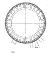
- the rotor (1) of the permanent magnet synchronous motor shown in Figure 1 is as External runners trained. It has a soft magnetic iron yoke (2) on its Inside permanent magnets (3) with a rectangular cross section are attached as rotor poles. The width of the permanent magnets (31) is smaller than the pole pitch of the rotor (1), whereby Gaps (4) between the permanent magnets (31) are formed.
- the stator laminated core (5) has a number of pronounced stator poles (6) on the circumference, which are provided with stator windings (7) (see FIG. 2).
- the windings (7) are over winding bodies (8) insulated against the stator laminated core (5).
- the ratio of rotor poles to stator poles is 4/3.
- the tooth heads (61) of the stator poles (6) have a curvature (611) in their edge areas such that the air gap d R between the permanent magnets (3) and the tooth head flanks (612) is 4 to 6 times larger than the air gap d M between the permanent magnets (3) and the tooth tip centers (613). With air gaps of approximately 1.2 mm, the air gap d R between the permanent magnets (3) and the tooth tip flanks (612) is 3 to 5 times larger than the air gap d M between the permanent magnets (3) and the tooth tip centers (613). In the middle (613), the tooth heads (61) have a flattened section, which forms a constant air gap d M with the permanent magnet (3).
- the ratio a of the tooth tip width b Z to the pole pitch ⁇ P of the starter is 0.7 ... 0.8, which in turn leads to stator tooth width - to - slot width ratios of 2.33 ... 4.
- FIG. 3 shows a section of a permanent magnet-excited synchronous motor with curved tooth heads (61), in which the permanent magnets (32) are designed in the shape of a segment of a circle.
- the width of the permanent magnets (32) corresponds approximately to the pole pitch of the rotor (1), so that a closed arrangement of the magnets (3) is achieved.
- this has a curvature corresponding to the radius of the rotor (1). Since a flat design of the tooth heads (61) only leads to a deviation in the range of a tenth of a millimeter, this is also conceivable.
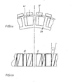
- FIGS. 4a and 4b show a section of a further permanent magnet-excited synchronous motor with block magnets (31) in a side view and a top view.
- the stator core (51) and thus the tooth tips (62) are set.
- a significant reduction in the reluctance torques is achieved by setting the stator laminated core (51) or the tooth tips (62) by an angle ⁇ of 26 ° ... 30 ° electrically, based on a stator pole pitch ⁇ P.
- the tooth heads (62) are designed in such a way that the air gap between the tooth heads and the permanent magnets (3) is almost homogeneous.
- the ratio of magnetic poles to stator poles (6) is also 4/3 in this case too.
- the permanent magnets (3) are rectangular in the embodiment shown. However, with the same shape of the stator poles (6), segment-shaped permanent magnets can also be used (3) can be used. To further reduce the reluctance moments, the Tooth heads (62) with a curvature (not shown) in the dimensions described above be provided.
Landscapes
- Engineering & Computer Science (AREA)
- Power Engineering (AREA)
- Textile Engineering (AREA)
- Permanent Magnet Type Synchronous Machine (AREA)
- Iron Core Of Rotating Electric Machines (AREA)
- Permanent Field Magnets Of Synchronous Machinery (AREA)
- Polarising Elements (AREA)
- Disintegrating Or Milling (AREA)
Description
- Figur 1
- den prinzipiellen Aufbau eines permanentmagneterregten Synchronmotors mit Blockmagneten (31) und konvexen Statorpolen (6)
- Figur 2
- einen Ausschnitt aus Figur 1
- Figur 3
- einen Ausschnitt eines permanentmagneterregten Synchronmotors mit Segmentmagneten (32) und konvexen Statorpolen (6)
- Figur 4 a,b
- einen Ausschnitt eines permanentmagneterregten Synchronmotors mit Blockmagneten (31) und geschränkten Statorpolen in Seitenansicht und Draufsicht
Claims (6)
- Wäschebehandlungsgerät wie Waschmaschine, Wäschetrockner oder Waschtrockner mit einer drehbar gelagerten Trommel mit mindestens annähernd horizontaler Drehachse, und mit einem auf der Trommelwelle angeordneten Antriebsmotor in Form eines permanentmagneterregten Synchronmotors, dessen Stator mit einer Wicklung (7) versehen ist, welche durch einen Umrichter bestromt wird, wobei die Wicklung (7) als Einzelpolwicklung ausgeführt ist, wobei die Anzahl der Statorpole und der Magnetpole ungleich ist, und wobei als Umrichter ein Frequenzumrichter verwendet wird, dessen Ausgangsspannung derart eingestellt ist, daß sich in allen Wicklungssträngen kontinuierliche Ströme ausbilden,
dadurch gekennzeichnet, daß die Zahnköpfe (61) der Statorpole mindestens in ihren Randbereichen eine derart dimensionierte Krümmung (611) aufweisen, daß der Luftspalt (dR) zwischen dem Permanentmagneten (31, 3) und den Zahnflanken 3 bis 6 mal größer als der Luftspalt (dM) zwischen dem Permanentmagneten (31, 3) und der Zahnkopfmitte (613) ist. - Wäschebehandlungsgerät wie Waschmaschine, Wäschetrockner oder Waschtrockner mit einer drehbar gelagerten Trommel mit mindestens annähernd horizontaler Drehachse, und mit einem auf der Trommelwelle angeordneten Antriebsmotor in Form eines permanentmagneterregten Synchronmotors, dessen Stator mit einer Wicklung (7) versehen ist, welche durch einen Umrichter bestromt wird, wobei die Wicklung (7) als Einzelpolwicklung ausgeführt ist, wobei die Anzahl der Statorpole und der Magnetpole ungleich ist, und wobei als Umrichter ein Frequenzumrichter verwendet wird, dessen Ausgangsspannung derart eingestellt ist, daß sich in allen Wicklungssträngen kontinuierliche Ströme ausbilden,
dadurch gekennzeichnet, daß der Luftspalt (dM) zwischen dem Permanentmagneten (31,3) und der Zahnkopfmitte (613) ca. 1,2 mm beträgt und daß die Zahnköpfe der Statorpole mindestens in ihren Randbereichen eine derart dimensionierte Krümmung (611) aufweisen, daß der Luftspalt (dR) zwischen dem Permanentmagneten (3) und den Zahnflanken (612) 3 bis 5 mal größer als der Luftspalt (dM) zwischen dem Permanentmagneten (3) und der Zahnkopfmitte (613) ist. - Wäschebehandlungsgerät nach Anspruch 1 oder 2,
dadurch gekennzeichnet, daß das Verhältnis der Zahnkopfbreite bZ zur Polteilung τP 0,7 ... 0,8, beträgt. - Wäschebehandlungsgerät nach einem oder mehreren der Ansprüche 1 bis 3,
dadurch gekennzeichnet, daß die Zahnköpfe (61) der Statorpole in der Mitte einen abgeflachten Teilbereich (613) aufweisen, welcher mit dem Permanentmagneten (3) einen annähernd konstanten Luftspalt bildet. - Wäschebehandlungsgerät wie Waschmaschine, Wäschetrockner oder Waschtrockner mit einer drehbar gelagerten Trommel mit mindestens annähernd horizontaler Drehachse, und mit einem auf der Trommelwelle angeordneten Antriebsmotor in Form eines permanentmagneterregten Synchronmotors, dessen Stator mit einer Wicklung (7) versehen ist, welche durch einen Umrichter bestromt wird, wobei die Wicklung (7) als Einzelpolwicklung ausgeführt ist, wobei die Anzahl der Statorpole und der Magnetpole ungleich ist, und wobei als Umrichter ein Frequenzumrichter verwendet wird, dessen Ausgangsspannung derart eingestellt ist, daß sich in allen Wicklungssträngen kontinuierliche Ströme ausbilden
dadurch gekennzeichnet, daß das Statorblechpaket (5) bezogen auf die Statorpolteilung eine Schränkung α von 25° el bis 30° el aufweist. - Wäschebehandlungsgerät wie Waschmaschine, Wäschetrockner oder Waschtrockner nach Anspruch 5 und einem der Ansprüche 1 bis 4.
Applications Claiming Priority (2)
| Application Number | Priority Date | Filing Date | Title |
|---|---|---|---|
| DE19836944A DE19836944A1 (de) | 1998-02-17 | 1998-08-17 | Wäschebehandlungsgerät |
| DE19836944 | 1998-08-17 |
Publications (4)
| Publication Number | Publication Date |
|---|---|
| EP0982425A2 EP0982425A2 (de) | 2000-03-01 |
| EP0982425A3 EP0982425A3 (de) | 2000-03-08 |
| EP0982425B1 true EP0982425B1 (de) | 2003-10-01 |
| EP0982425B2 EP0982425B2 (de) | 2007-08-29 |
Family
ID=7877575
Family Applications (1)
| Application Number | Title | Priority Date | Filing Date |
|---|---|---|---|
| EP99115791A Expired - Lifetime EP0982425B2 (de) | 1998-08-17 | 1999-08-11 | Wäschebehandlungsgerät |
Country Status (3)
| Country | Link |
|---|---|
| EP (1) | EP0982425B2 (de) |
| AT (1) | ATE251247T1 (de) |
| DE (1) | DE59907166D1 (de) |
Families Citing this family (7)
| Publication number | Priority date | Publication date | Assignee | Title |
|---|---|---|---|---|
| US6946760B2 (en) * | 2003-10-22 | 2005-09-20 | Emerson Electric Co. | Brushless permanent magnet motor with high power density, low cogging and low vibration |
| KR100720551B1 (ko) * | 2005-11-18 | 2007-05-22 | 엘지전자 주식회사 | 세탁기용 직결식 유도 모터와 이를 구비한 세탁기 |
| FR2894403A1 (fr) * | 2005-12-02 | 2007-06-08 | Leroy Somer Moteurs | Machine electrique tournante a ondulations de couple reduites |
| DE102007030508B4 (de) * | 2007-06-30 | 2014-10-16 | Schaeffler Technologies Gmbh & Co. Kg | Waschmaschinen-Direktantrieb |
| DE202011111030U1 (de) | 2010-12-22 | 2018-07-05 | Fisher & Paykel Appliances Limited | verbesserte Vorrichtung, Motor oder Stator |
| CN105453385B (zh) * | 2013-08-14 | 2019-05-03 | 雅马哈发动机株式会社 | 同步驱动电机 |
| CN117018962B (zh) * | 2023-08-24 | 2026-04-10 | 常德市三一机械有限公司 | 滚筒限位装置、搅拌设备、滚筒位置调整方法和控制器 |
Family Cites Families (8)
| Publication number | Priority date | Publication date | Assignee | Title |
|---|---|---|---|---|
| DE4335966C2 (de) * | 1993-10-21 | 1998-07-16 | Fhp Motors Gmbh | Antriebsvorrichtung für eine Wasch- oder eine ähnliche Maschine mit einem kollektorlosen Gleichstrommotor |
| DE4341832C2 (de) † | 1993-12-08 | 2001-11-08 | Fhp Motors Gmbh | Waschautomat |
| JPH07308057A (ja) * | 1994-05-11 | 1995-11-21 | Yaskawa Electric Corp | 永久磁石形同期電動機 |
| TR199802748T2 (xx) * | 1996-07-02 | 1999-03-22 | Domel Elektromotorji In Gospodinjski Aparati, D.O.O. | Bir çamaşır makinası tamburunun doğrudan tahriki için elektronik komütasyonlu motor. |
| JP3290354B2 (ja) † | 1996-07-05 | 2002-06-10 | 株式会社東芝 | 洗濯機及び洗濯機の駆動方法 |
| NZ314016A (en) † | 1996-12-23 | 1998-01-26 | Toshiba Kk | Washing machine with motor driving via clutch to rotate agitator only or agitator and clutch |
| WO1998036123A2 (de) | 1997-02-17 | 1998-08-20 | Miele & Cie. Gmbh & Co. | Wäschebehandlungsgerät mit einem auf der trommelwelle angeordneten antriebsmotor |
| GB9801187D0 (en) * | 1998-01-20 | 1998-03-18 | Switched Reluctance Drives Ltd | Noise reduction in reluctance machines |
-
1999
- 1999-08-11 EP EP99115791A patent/EP0982425B2/de not_active Expired - Lifetime
- 1999-08-11 DE DE59907166T patent/DE59907166D1/de not_active Expired - Lifetime
- 1999-08-11 AT AT99115791T patent/ATE251247T1/de not_active IP Right Cessation
Also Published As
| Publication number | Publication date |
|---|---|
| DE59907166D1 (de) | 2003-11-06 |
| EP0982425A3 (de) | 2000-03-08 |
| ATE251247T1 (de) | 2003-10-15 |
| EP0982425A2 (de) | 2000-03-01 |
| EP0982425B2 (de) | 2007-08-29 |
Similar Documents
| Publication | Publication Date | Title |
|---|---|---|
| DE3740725C2 (de) | ||
| EP1552594B1 (de) | Permanenterregte synchronmaschine | |
| DE69917557T2 (de) | Untersynchrone elektrische Reluktanzmaschine | |
| DE102019218437A1 (de) | Rotor für eine Elektromaschine und Verfahren zur Herstellung eines Rotors | |
| DE3331194A1 (de) | Kollektorloser gleichstrommotor mit dreistraengiger, ungesehnter statorwicklung | |
| EP0982425B1 (de) | Wäschebehandlungsgerät | |
| DE3331002A1 (de) | Elektrische maschine | |
| DE3320805C2 (de) | ||
| DE60214294T2 (de) | Wechselstromgenerator | |
| EP0786851A1 (de) | Haushaltsgerät-Pumpenantrieb mit einem selbstanlaufenden Einphasen-Synchronmotor | |
| DE19836944A1 (de) | Wäschebehandlungsgerät | |
| DE202019105634U1 (de) | Ein Gleichspannungs Motor-Dynamo | |
| EP4487454A1 (de) | Elektromotor und zugehörige verwendung | |
| DE19848909A1 (de) | Segmentierte elektrische Maschine mit reduzierten Rastkräften bzw. reduziertem Rastmoment | |
| EP0699357A1 (de) | Reluktanzmotor, insbesondere zum antrieb eines waschautomaten | |
| DE102009017870B4 (de) | Stator für einen Gleichstrommotor | |
| DE3908515C2 (de) | ||
| DE643888C (de) | Selbstanlaufender Einphasen-Wechselstrom-Synchronmotor | |
| WO2009098172A2 (de) | Permanentmagneterregte elektrische maschine zum antrieb einer komponente eines hausgeräts, satz umfassend solche permanentmagneterregte elektrische maschinen und hausgerät mit einer derartigen maschine | |
| DE102010013748A1 (de) | Vorrichtung nach Art einer elektrischen Maschine mit einem permanentmagnetischen Rotor und einem Stator | |
| DE4212547C2 (de) | Reluktanzmotor, insbesondere geschalteter Reluktanzmotor für einen Positionierantrieb | |
| DE4439494C1 (de) | Drehstromgenerator | |
| DE102007027896A1 (de) | Elektronisch kommutierter Motor mit verbessertem Stator | |
| EP1102386A2 (de) | Gleichstrommaschine | |
| DE668019C (de) | Universalkleinmotor ohne Kompensationswicklung zum wahlweisen Anschluss an ein Gleich- oder Wechselstromnetz |
Legal Events
| Date | Code | Title | Description |
|---|---|---|---|
| PUAI | Public reference made under article 153(3) epc to a published international application that has entered the european phase |
Free format text: ORIGINAL CODE: 0009012 |
|
| PUAL | Search report despatched |
Free format text: ORIGINAL CODE: 0009013 |
|
| AK | Designated contracting states |
Kind code of ref document: A2 Designated state(s): AT BE CH CY DE DK ES FI FR GB GR IE IT LI LU MC NL PT SE |
|
| AX | Request for extension of the european patent |
Free format text: AL;LT;LV;MK;RO;SI |
|
| AK | Designated contracting states |
Kind code of ref document: A3 Designated state(s): AT BE CH CY DE DK ES FI FR GB GR IE IT LI LU MC NL PT SE |
|
| AX | Request for extension of the european patent |
Free format text: AL;LT;LV;MK;RO;SI |
|
| 17P | Request for examination filed |
Effective date: 20000809 |
|
| AKX | Designation fees paid |
Free format text: AT BE CH CY DE DK ES FI FR GB GR IE IT LI LU MC NL PT SE |
|
| 17Q | First examination report despatched |
Effective date: 20020726 |
|
| GRAH | Despatch of communication of intention to grant a patent |
Free format text: ORIGINAL CODE: EPIDOS IGRA |
|
| GRAH | Despatch of communication of intention to grant a patent |
Free format text: ORIGINAL CODE: EPIDOS IGRA |
|
| GRAH | Despatch of communication of intention to grant a patent |
Free format text: ORIGINAL CODE: EPIDOS IGRA |
|
| RAP1 | Party data changed (applicant data changed or rights of an application transferred) |
Owner name: MIELE & CIE. KG |
|
| GRAA | (expected) grant |
Free format text: ORIGINAL CODE: 0009210 |
|
| AK | Designated contracting states |
Kind code of ref document: B1 Designated state(s): AT BE CH CY DE DK ES FI FR GB GR IE IT LI LU MC NL PT SE |
|
| PG25 | Lapsed in a contracting state [announced via postgrant information from national office to epo] |
Ref country code: NL Free format text: LAPSE BECAUSE OF FAILURE TO SUBMIT A TRANSLATION OF THE DESCRIPTION OR TO PAY THE FEE WITHIN THE PRESCRIBED TIME-LIMIT Effective date: 20031001 Ref country code: IE Free format text: LAPSE BECAUSE OF FAILURE TO SUBMIT A TRANSLATION OF THE DESCRIPTION OR TO PAY THE FEE WITHIN THE PRESCRIBED TIME-LIMIT Effective date: 20031001 Ref country code: FI Free format text: LAPSE BECAUSE OF FAILURE TO SUBMIT A TRANSLATION OF THE DESCRIPTION OR TO PAY THE FEE WITHIN THE PRESCRIBED TIME-LIMIT Effective date: 20031001 Ref country code: CY Free format text: LAPSE BECAUSE OF FAILURE TO SUBMIT A TRANSLATION OF THE DESCRIPTION OR TO PAY THE FEE WITHIN THE PRESCRIBED TIME-LIMIT Effective date: 20031001 |
|
| REG | Reference to a national code |
Ref country code: GB Ref legal event code: FG4D Free format text: NOT ENGLISH |
|
| REG | Reference to a national code |
Ref country code: CH Ref legal event code: EP |
|
| REG | Reference to a national code |
Ref country code: IE Ref legal event code: FG4D Free format text: GERMAN |
|
| REF | Corresponds to: |
Ref document number: 59907166 Country of ref document: DE Date of ref document: 20031106 Kind code of ref document: P |
|
| PG25 | Lapsed in a contracting state [announced via postgrant information from national office to epo] |
Ref country code: SE Free format text: LAPSE BECAUSE OF FAILURE TO SUBMIT A TRANSLATION OF THE DESCRIPTION OR TO PAY THE FEE WITHIN THE PRESCRIBED TIME-LIMIT Effective date: 20040101 Ref country code: GR Free format text: LAPSE BECAUSE OF FAILURE TO SUBMIT A TRANSLATION OF THE DESCRIPTION OR TO PAY THE FEE WITHIN THE PRESCRIBED TIME-LIMIT Effective date: 20040101 Ref country code: DK Free format text: LAPSE BECAUSE OF FAILURE TO SUBMIT A TRANSLATION OF THE DESCRIPTION OR TO PAY THE FEE WITHIN THE PRESCRIBED TIME-LIMIT Effective date: 20040101 |
|
| PG25 | Lapsed in a contracting state [announced via postgrant information from national office to epo] |
Ref country code: ES Free format text: LAPSE BECAUSE OF FAILURE TO SUBMIT A TRANSLATION OF THE DESCRIPTION OR TO PAY THE FEE WITHIN THE PRESCRIBED TIME-LIMIT Effective date: 20040112 |
|
| GBT | Gb: translation of ep patent filed (gb section 77(6)(a)/1977) |
Effective date: 20040106 |
|
| NLV1 | Nl: lapsed or annulled due to failure to fulfill the requirements of art. 29p and 29m of the patents act | ||
| REG | Reference to a national code |
Ref country code: IE Ref legal event code: FD4D |
|
| PLBI | Opposition filed |
Free format text: ORIGINAL CODE: 0009260 |
|
| PLBQ | Unpublished change to opponent data |
Free format text: ORIGINAL CODE: EPIDOS OPPO |
|
| PLAZ | Examination of admissibility of opposition: despatch of communication + time limit |
Free format text: ORIGINAL CODE: EPIDOSNOPE2 |
|
| ET | Fr: translation filed | ||
| PLAX | Notice of opposition and request to file observation + time limit sent |
Free format text: ORIGINAL CODE: EPIDOSNOBS2 |
|
| PLBA | Examination of admissibility of opposition: reply received |
Free format text: ORIGINAL CODE: EPIDOSNOPE4 |
|
| PG25 | Lapsed in a contracting state [announced via postgrant information from national office to epo] |
Ref country code: LU Free format text: LAPSE BECAUSE OF NON-PAYMENT OF DUE FEES Effective date: 20040811 Ref country code: AT Free format text: LAPSE BECAUSE OF NON-PAYMENT OF DUE FEES Effective date: 20040811 |
|
| 26 | Opposition filed |
Opponent name: FISHER & PAYKEL LIMITED Effective date: 20040629 |
|
| PG25 | Lapsed in a contracting state [announced via postgrant information from national office to epo] |
Ref country code: MC Free format text: LAPSE BECAUSE OF NON-PAYMENT OF DUE FEES Effective date: 20040831 Ref country code: LI Free format text: LAPSE BECAUSE OF NON-PAYMENT OF DUE FEES Effective date: 20040831 Ref country code: CH Free format text: LAPSE BECAUSE OF NON-PAYMENT OF DUE FEES Effective date: 20040831 Ref country code: BE Free format text: LAPSE BECAUSE OF NON-PAYMENT OF DUE FEES Effective date: 20040831 |
|
| PLBB | Reply of patent proprietor to notice(s) of opposition received |
Free format text: ORIGINAL CODE: EPIDOSNOBS3 |
|
| BERE | Be: lapsed |
Owner name: *MIELE & CIE. K.G. Effective date: 20040831 |
|
| REG | Reference to a national code |
Ref country code: CH Ref legal event code: PL |
|
| PLAB | Opposition data, opponent's data or that of the opponent's representative modified |
Free format text: ORIGINAL CODE: 0009299OPPO |
|
| R26 | Opposition filed (corrected) |
Opponent name: FISHER & PAYKEL LIMITED Effective date: 20040629 |
|
| REG | Reference to a national code |
Ref country code: GB Ref legal event code: 746 Effective date: 20061019 |
|
| PUAH | Patent maintained in amended form |
Free format text: ORIGINAL CODE: 0009272 |
|
| STAA | Information on the status of an ep patent application or granted ep patent |
Free format text: STATUS: PATENT MAINTAINED AS AMENDED |
|
| 27A | Patent maintained in amended form |
Effective date: 20070829 |
|
| AK | Designated contracting states |
Kind code of ref document: B2 Designated state(s): AT BE CH CY DE DK ES FI FR GB GR IE IT LI LU MC NL PT SE |
|
| REG | Reference to a national code |
Ref country code: ES Ref legal event code: FD2A Effective date: 20040812 |
|
| GBTA | Gb: translation of amended ep patent filed (gb section 77(6)(b)/1977) | ||
| BERE | Be: lapsed |
Owner name: *MIELE & CIE. K.G. Effective date: 20040831 |
|
| PG25 | Lapsed in a contracting state [announced via postgrant information from national office to epo] |
Ref country code: PT Free format text: LAPSE BECAUSE OF NON-PAYMENT OF DUE FEES Effective date: 20040301 |
|
| ET3 | Fr: translation filed ** decision concerning opposition | ||
| PGFP | Annual fee paid to national office [announced via postgrant information from national office to epo] |
Ref country code: FR Payment date: 20110829 Year of fee payment: 13 Ref country code: GB Payment date: 20110824 Year of fee payment: 13 |
|
| PGFP | Annual fee paid to national office [announced via postgrant information from national office to epo] |
Ref country code: IT Payment date: 20110826 Year of fee payment: 13 |
|
| PGFP | Annual fee paid to national office [announced via postgrant information from national office to epo] |
Ref country code: DE Payment date: 20120820 Year of fee payment: 14 |
|
| GBPC | Gb: european patent ceased through non-payment of renewal fee |
Effective date: 20120811 |
|
| REG | Reference to a national code |
Ref country code: FR Ref legal event code: ST Effective date: 20130430 |
|
| PG25 | Lapsed in a contracting state [announced via postgrant information from national office to epo] |
Ref country code: IT Free format text: LAPSE BECAUSE OF NON-PAYMENT OF DUE FEES Effective date: 20120811 |
|
| PG25 | Lapsed in a contracting state [announced via postgrant information from national office to epo] |
Ref country code: GB Free format text: LAPSE BECAUSE OF NON-PAYMENT OF DUE FEES Effective date: 20120811 |
|
| PG25 | Lapsed in a contracting state [announced via postgrant information from national office to epo] |
Ref country code: FR Free format text: LAPSE BECAUSE OF NON-PAYMENT OF DUE FEES Effective date: 20120831 |
|
| PG25 | Lapsed in a contracting state [announced via postgrant information from national office to epo] |
Ref country code: DE Free format text: LAPSE BECAUSE OF NON-PAYMENT OF DUE FEES Effective date: 20140301 |
|
| REG | Reference to a national code |
Ref country code: DE Ref legal event code: R119 Ref document number: 59907166 Country of ref document: DE Effective date: 20140301 |