EP0980801A2 - Scheibenwischvorrichtung- und Verfahren - Google Patents
Scheibenwischvorrichtung- und Verfahren Download PDFInfo
- Publication number
- EP0980801A2 EP0980801A2 EP99114998A EP99114998A EP0980801A2 EP 0980801 A2 EP0980801 A2 EP 0980801A2 EP 99114998 A EP99114998 A EP 99114998A EP 99114998 A EP99114998 A EP 99114998A EP 0980801 A2 EP0980801 A2 EP 0980801A2
- Authority
- EP
- European Patent Office
- Prior art keywords
- recited
- flexible arm
- load
- linkage
- wiper
- Prior art date
- Legal status (The legal status is an assumption and is not a legal conclusion. Google has not performed a legal analysis and makes no representation as to the accuracy of the status listed.)
- Granted
Links
- 238000000034 method Methods 0.000 title claims abstract description 23
- 239000002131 composite material Substances 0.000 claims abstract description 7
- 229910000831 Steel Inorganic materials 0.000 claims abstract description 5
- 239000010959 steel Substances 0.000 claims abstract description 5
- 239000003365 glass fiber Substances 0.000 claims description 5
- 239000000463 material Substances 0.000 claims description 4
- 239000003733 fiber-reinforced composite Substances 0.000 claims 3
- 229920001187 thermosetting polymer Polymers 0.000 claims 2
- 230000006835 compression Effects 0.000 abstract description 3
- 238000007906 compression Methods 0.000 abstract description 3
- 229920000728 polyester Polymers 0.000 description 3
- 239000003822 epoxy resin Substances 0.000 description 2
- 229920000647 polyepoxide Polymers 0.000 description 2
- 238000006073 displacement reaction Methods 0.000 description 1
- 230000000694 effects Effects 0.000 description 1
- 239000011152 fibreglass Substances 0.000 description 1
- 230000008014 freezing Effects 0.000 description 1
- 238000007710 freezing Methods 0.000 description 1
- 239000005340 laminated glass Substances 0.000 description 1
- 239000002245 particle Substances 0.000 description 1
- 238000010008 shearing Methods 0.000 description 1
Images


Classifications
-
- B—PERFORMING OPERATIONS; TRANSPORTING
- B60—VEHICLES IN GENERAL
- B60S—SERVICING, CLEANING, REPAIRING, SUPPORTING, LIFTING, OR MANOEUVRING OF VEHICLES, NOT OTHERWISE PROVIDED FOR
- B60S1/00—Cleaning of vehicles
- B60S1/02—Cleaning windscreens, windows or optical devices
- B60S1/04—Wipers or the like, e.g. scrapers
- B60S1/06—Wipers or the like, e.g. scrapers characterised by the drive
- B60S1/16—Means for transmitting drive
- B60S1/18—Means for transmitting drive mechanically
- B60S1/24—Means for transmitting drive mechanically by rotary cranks
- B60S1/245—Means for transmitting drive mechanically by rotary cranks with particular rod arrangements between the motor driven axle and the wiper arm axle
-
- F—MECHANICAL ENGINEERING; LIGHTING; HEATING; WEAPONS; BLASTING
- F16—ENGINEERING ELEMENTS AND UNITS; GENERAL MEASURES FOR PRODUCING AND MAINTAINING EFFECTIVE FUNCTIONING OF MACHINES OR INSTALLATIONS; THERMAL INSULATION IN GENERAL
- F16C—SHAFTS; FLEXIBLE SHAFTS; ELEMENTS OR CRANKSHAFT MECHANISMS; ROTARY BODIES OTHER THAN GEARING ELEMENTS; BEARINGS
- F16C7/00—Connecting-rods or like links pivoted at both ends; Construction of connecting-rod heads
- F16C7/02—Constructions of connecting-rods with constant length
-
- F—MECHANICAL ENGINEERING; LIGHTING; HEATING; WEAPONS; BLASTING
- F16—ENGINEERING ELEMENTS AND UNITS; GENERAL MEASURES FOR PRODUCING AND MAINTAINING EFFECTIVE FUNCTIONING OF MACHINES OR INSTALLATIONS; THERMAL INSULATION IN GENERAL
- F16B—DEVICES FOR FASTENING OR SECURING CONSTRUCTIONAL ELEMENTS OR MACHINE PARTS TOGETHER, e.g. NAILS, BOLTS, CIRCLIPS, CLAMPS, CLIPS OR WEDGES; JOINTS OR JOINTING
- F16B2200/00—Constructional details of connections not covered for in other groups of this subclass
- F16B2200/63—Frangible connections
-
- F—MECHANICAL ENGINEERING; LIGHTING; HEATING; WEAPONS; BLASTING
- F16—ENGINEERING ELEMENTS AND UNITS; GENERAL MEASURES FOR PRODUCING AND MAINTAINING EFFECTIVE FUNCTIONING OF MACHINES OR INSTALLATIONS; THERMAL INSULATION IN GENERAL
- F16C—SHAFTS; FLEXIBLE SHAFTS; ELEMENTS OR CRANKSHAFT MECHANISMS; ROTARY BODIES OTHER THAN GEARING ELEMENTS; BEARINGS
- F16C11/00—Pivots; Pivotal connections
- F16C11/04—Pivotal connections
- F16C11/06—Ball-joints; Other joints having more than one degree of angular freedom, i.e. universal joints
- F16C11/0695—Mounting of ball-joints, e.g. fixing them to a connecting rod
-
- F—MECHANICAL ENGINEERING; LIGHTING; HEATING; WEAPONS; BLASTING
- F16—ENGINEERING ELEMENTS AND UNITS; GENERAL MEASURES FOR PRODUCING AND MAINTAINING EFFECTIVE FUNCTIONING OF MACHINES OR INSTALLATIONS; THERMAL INSULATION IN GENERAL
- F16C—SHAFTS; FLEXIBLE SHAFTS; ELEMENTS OR CRANKSHAFT MECHANISMS; ROTARY BODIES OTHER THAN GEARING ELEMENTS; BEARINGS
- F16C2326/00—Articles relating to transporting
- F16C2326/01—Parts of vehicles in general
- F16C2326/09—Windscreen wipers, e.g. pivots therefore
-
- Y—GENERAL TAGGING OF NEW TECHNOLOGICAL DEVELOPMENTS; GENERAL TAGGING OF CROSS-SECTIONAL TECHNOLOGIES SPANNING OVER SEVERAL SECTIONS OF THE IPC; TECHNICAL SUBJECTS COVERED BY FORMER USPC CROSS-REFERENCE ART COLLECTIONS [XRACs] AND DIGESTS
- Y10—TECHNICAL SUBJECTS COVERED BY FORMER USPC
- Y10T—TECHNICAL SUBJECTS COVERED BY FORMER US CLASSIFICATION
- Y10T74/00—Machine element or mechanism
- Y10T74/11—Tripping mechanism
-
- Y—GENERAL TAGGING OF NEW TECHNOLOGICAL DEVELOPMENTS; GENERAL TAGGING OF CROSS-SECTIONAL TECHNOLOGIES SPANNING OVER SEVERAL SECTIONS OF THE IPC; TECHNICAL SUBJECTS COVERED BY FORMER USPC CROSS-REFERENCE ART COLLECTIONS [XRACs] AND DIGESTS
- Y10—TECHNICAL SUBJECTS COVERED BY FORMER USPC
- Y10T—TECHNICAL SUBJECTS COVERED BY FORMER US CLASSIFICATION
- Y10T74/00—Machine element or mechanism
- Y10T74/18—Mechanical movements
- Y10T74/18056—Rotary to or from reciprocating or oscillating
- Y10T74/18184—Crank, pitman, and lever
- Y10T74/182—Multiple levers
-
- Y—GENERAL TAGGING OF NEW TECHNOLOGICAL DEVELOPMENTS; GENERAL TAGGING OF CROSS-SECTIONAL TECHNOLOGIES SPANNING OVER SEVERAL SECTIONS OF THE IPC; TECHNICAL SUBJECTS COVERED BY FORMER USPC CROSS-REFERENCE ART COLLECTIONS [XRACs] AND DIGESTS
- Y10—TECHNICAL SUBJECTS COVERED BY FORMER USPC
- Y10T—TECHNICAL SUBJECTS COVERED BY FORMER US CLASSIFICATION
- Y10T74/00—Machine element or mechanism
- Y10T74/19—Gearing
- Y10T74/1956—Adjustable
- Y10T74/19585—Fixed axes
- Y10T74/19595—Automatic control
- Y10T74/196—Parallel shafts
-
- Y—GENERAL TAGGING OF NEW TECHNOLOGICAL DEVELOPMENTS; GENERAL TAGGING OF CROSS-SECTIONAL TECHNOLOGIES SPANNING OVER SEVERAL SECTIONS OF THE IPC; TECHNICAL SUBJECTS COVERED BY FORMER USPC CROSS-REFERENCE ART COLLECTIONS [XRACs] AND DIGESTS
- Y10—TECHNICAL SUBJECTS COVERED BY FORMER USPC
- Y10T—TECHNICAL SUBJECTS COVERED BY FORMER US CLASSIFICATION
- Y10T74/00—Machine element or mechanism
- Y10T74/21—Elements
- Y10T74/2142—Pitmans and connecting rods
- Y10T74/2144—Yieldable
- Y10T74/2148—Automatic release
Definitions
- This invention relates to a windshield wiper system and, more particularly, to a windshield wiper system which utilizes at least one flexible member which bends or flexes to compensate for compression loads in excess of a predetermined load.
- wiper arms having wiper blades thereon are driven from a park position, where the blades are often situated at either the bottom of or below a windshield of a vehicle, through an inwipe position, to an outwipe position.
- the blades oscillate between the inwipe and outwipe positions to clean the windshield of debris or particles, such as ice, snow or other debris. It is not uncommon that snow or ice can accumulate on the windshield and prevent the wiper blades from, for example, fully retracting from the inwipe position to the park position when a user actuates a wiper switch to an off position.
- this invention comprises a windshield wiper drive linkage for use in a wiper system comprising a plurality of linkage arms, at least one of the plurality of linkage arms comprising a flexible arm which bends to facilitate preventing damage to components in the wiper system when a compressive load applied to at least one of the plurality of linkage arms exceeds a predetermined load as a result of a fatigue condition.
- this invention comprises a wiper system comprising a first wiper, a second wiper, a windshield wiper drive linkage coupled to the first and second wipers, a drive motor coupled to the windshield wiper drive linkage and the windshield wiper drive linkage comprising a plurality of linkage arms coupled to the first and second wipers and the drive motor, at least one of the linkage arms comprising a flexible arm which bends to facilitate preventing damage to components in the wiper system when a compressive load applied to one linkage arms exceeds a predetermined load as a result of a fatigue condition.
- this invention comprises a method of driving at least one wiper blade in a windshield wiper system comprising the steps of providing a drive motor for driving the at least one wiper blade, providing linkage for linking at least one wiper blade to the drive motor, the linkage comprising a flexible arm which bends to facilitate preventing damage to components in the wiper system when a compressive load applied to at least one linkage arms exceeds a predetermined load as a result of a fatigue condition.
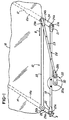
- a windshield wiper system 10 comprising a first wiper 12 and a second wiper 14 for wiping a windshield 16.
- the wiper 12 comprises a wiper arm 12a and blade 12b
- wiper 14 comprises a wiper arm 14a and blade 14b.
- the wiper system 10 further comprises a windshield wiper drive linkage or linking means 18 comprising a first link arm 18 on which a drive motor 20 is fastened thereto by conventional means, such as a weld, nut and bolt, or the like.
- the frame link 18 comprises a first pivot housing 20 and a second pivot housing 22 which is secured thereto.
- the pivot housings 20 and 22 comprise a first rotatable pivot housing shaft 20a and a second rotatable pivot housing shaft 22a which are drivingly coupled to wiper blades 12 and 14 (shown in phantom in Fig. 1), respectively.
- the first rotatable pivot housing shaft 20a is coupled to a first end 24a of a drive plate 24.
- the pivot housing shaft 22a is secured to a first end 26a of a second drive plate 26, as best illustrated in Fig. 1.
- An operating or "slave" link 23 couples a second end 24b of first drive plate 24 to a second end 26b of second drive plate 26 such that the drive plates 24 and 26 operate synchronously to rotatably drive the pivot housing shafts 22a and 24a in the direction of arrow A, thereby driving the wiper blades 12b and 14b.
- the linkage or linking means 18 further comprises a motor drive link or flexible arm 28 having a first end 28a coupled to the second end 24b of the drive plate 24.
- the motor drive link or flexible arm 28 further comprises a second end 28b which is coupled to an output shaft 20a of motor 20 via a crank arm 30.
- the crank arm 30 comprises a crank arm ball (not shown) and the drive plate 24 comprises a drive plate ball (not shown).
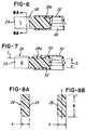
- the arm 28 comprises an elongated rectangular member 29 (Figs. 3-5) comprising a socket 32 and socket 34 which are over-molded thereon.
- the first end 28a of motor drive link or flexible arm 28 comprises the socket 32 for mounting onto the drive plate ball (not shown) on drive plates 24, and second end 28b of motor drive link or flexible arm 28 comprises the socket 34 for receiving crank arm ball (not shown) on crank arm 30.
- the first and second ends 28a and 28b comprise the sockets 32 and 34, respectively.
- socket 32 (Fig. 6) defines a socket area 40, respectively. It has been found that it is desirable to align the centerline CL (Fig. 5) with the axis of shafts 20a, 22a and 24a when the wipers 12 and 14 are in the park position.
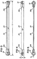
- flexible arm 28 defines a length L1, which in the embodiment being described is in excess of 250 mm.
- a predetermined load such as at least 30 percent of a maximum working load of flexible member 28 as defined below
- the flexible arm 28 begins to flex or bend. This causes the flexible arm 28 to shorten to a length L2, illustrated in Fig. 2D, and this length L2 is shorter than length L1.
- the compressive load remains substantially constant as the flexible arm 28 continues to bend or flex and shorten for at least 5mm after the compressive load achieves the predetermined load.
- the flexible arm 28 is preferably made from a composite material of the type described later herein relative to Table 1.
- the flexible arm 28 is generally rectangular in cross-section and is generally elongated (Figs. 3-5). It should be appreciated that the member 28 could be elliptical, circular or of some other geometry as desired.
- the length L1 (Figs. 2A and 3) of flexible arm 28 is on the order of at least 250mm, but it could be any suitable length depending on the application.
- Fig. 7 illustrates another embodiment of the invention where the flexible member 28 may be provided with sockets 32 and 34 with shear relief areas 50 and 52 which enable the end caps 32 and 34 to shear away or separate from member 29 when a predetermined stress applied to the flexible member 28.
- the predetermined stress is selected to be just slightly below a break point or maximum load of the member 29 so that, when the member 29 is about to reach its break point, one or more of the sockets 32 or 34 are permitted to shear and separate themselves from member 29 to avoid breakage.
- the drive motor 20 When a user actuates a wiper switch (not shown) the drive motor 20 is energized to cause the wipers to move from a park position (PP) through an inwipe position (IWP) towards an outwipe position (OWP), back to the inwipe position and so on.
- the drive motor 20 drives the crank arm 30 to drive the motor drive link or flexible arm 28 to attempt to drive wipers 12 and 14 from the inwipe position to the park position.
- the motor 20 rotatably drives crank arm 30 which, in turn, drives the motor drive link or flexible arm 28 to drive the second end 24b of drive plate 24 in the direction of arrow B in Fig. 1.
- the operating link 23 responds by directly driving second end 26b of drive plate 26.
- the movement of drive plates 24 and 26, in turn, rotatably drive the pivot housing shafts 20a and 22a, respectively, to drive the first and second wipers 12 and 14 across the face of windshield 16 in response to rotation of the motor drive shaft 20a.
- a fatigue condition may occur when snow, ice or some other material or condition (illustrated as 49 in Figs. 2C and 2D) prevents the wiper blades from moving, for example, from the inwipe position to the park position.
- the motor 20 continues to drive the motor drive link or flexible arm 28. Consequently, a compressive force or load is applied to the arm 28.
- the flexible arm 28 bends or flexes to facilitate preventing damage to the various components in the wiper system 10 when the load applied to the flexible arm 28 exceeds a predetermined load described later herein.
- the flexible arm 28 flexes to accommodate the compressive force or load mentioned earlier when the compressive force or load exceeding the predetermined load as a result of the fatigue condition.
- Polyester (NCC) 300 20 3.4 290.02 238.47 4. Fiberglass 305 31.7 2.42 237.98 219.10
- the four different composite materials included a molded glass laminate provided by Red Seal Electric Company of Cleveland, Ohio; a molded epoxy resin provided by International Paper of Hampton, South Carolina; a protruded polyester with oriented glass fibers provided by National Composite Center of Dayton, Ohio; and a protruded polyester with uni-directional glass fibers provided by Polygon Company of Walkerton, Indiana.
- Fig. 9 graphically illustrates the Instron testing machine results. Notice that, as the load on compressive arm 18 increased to in excess of 300 Newton, the flexible arm 18 began to bend or flex (as shown in Fig. 2D), thereby causing the load to be distributed across the flexible member 28. Notice that the load remains substantially constant even while the motor 20 (Fig. 1) continues to apply torque to the flexible arm 28.
- Figs. 10-13 illustrate another embodiment of the invention with like parts being identified with the same part numbers, except that a "prime" mark ("'") has been added thereto.
- the flexible arm 28' is generally circular in cross-section (as shown in Fig. 13) and comprises a plurality of areas of flex 62' at areas where the flexible member 28' defines an oval shape in cross section, as shown in Fig. 12.
- the points of weakness permit the flexible member 28' to flex at the areas 62' when the compressive load exceeds the predetermined load, such as 30 percent higher than a maximum working load of the flexible member 28'.
- the flexible member 28' defines a length L3 (Fig. 10) which is greater than the length L4 shown in Fig. 11.
Landscapes
- Engineering & Computer Science (AREA)
- General Engineering & Computer Science (AREA)
- Mechanical Engineering (AREA)
- Transmission Devices (AREA)
- Laminated Bodies (AREA)
- Motor Or Generator Frames (AREA)
- Body Structure For Vehicles (AREA)
Priority Applications (2)
| Application Number | Priority Date | Filing Date | Title |
|---|---|---|---|
| PCT/US1999/018457 WO2000009370A1 (en) | 1998-08-14 | 1999-08-13 | Windshield wiping system and method |
| JP2000564842A JP2003527988A (ja) | 1998-08-14 | 1999-08-13 | ウインドシールド払拭システムおよび方法 |
Applications Claiming Priority (2)
| Application Number | Priority Date | Filing Date | Title |
|---|---|---|---|
| US09/134,266 US6148470A (en) | 1998-08-14 | 1998-08-14 | Windshield wiping system |
| US134266 | 1998-08-14 |
Publications (3)
| Publication Number | Publication Date |
|---|---|
| EP0980801A2 true EP0980801A2 (de) | 2000-02-23 |
| EP0980801A3 EP0980801A3 (de) | 2002-08-21 |
| EP0980801B1 EP0980801B1 (de) | 2005-07-27 |
Family
ID=22462554
Family Applications (1)
| Application Number | Title | Priority Date | Filing Date |
|---|---|---|---|
| EP99114998A Expired - Lifetime EP0980801B1 (de) | 1998-08-14 | 1999-07-31 | Scheibenwischvorrichtung- und Verfahren |
Country Status (3)
| Country | Link |
|---|---|
| US (3) | US6148470A (de) |
| EP (1) | EP0980801B1 (de) |
| DE (1) | DE69926317T2 (de) |
Cited By (2)
| Publication number | Priority date | Publication date | Assignee | Title |
|---|---|---|---|---|
| EP1808285A1 (de) | 2006-01-17 | 2007-07-18 | Mecaplast Sam | Verstärkter Kunststoffgegenstand |
| CN111976654A (zh) * | 2019-05-30 | 2020-11-24 | 宁波市鄞州乐可机电科技有限公司 | 一种挡雨装置 |
Families Citing this family (25)
| Publication number | Priority date | Publication date | Assignee | Title |
|---|---|---|---|---|
| US6148470A (en) * | 1998-08-14 | 2000-11-21 | Valeo Electrical Systems, Inc. | Windshield wiping system |
| US7017224B2 (en) * | 2002-07-19 | 2006-03-28 | Valeo Electrical Systems, Inc. | Windshield wiper drive linkage arm with interior grooves |
| US6881373B2 (en) * | 2002-07-19 | 2005-04-19 | Valeo Electrical Systems, Inc. | Windshield wiping system manufacturing method |
| JP2005533715A (ja) * | 2002-07-19 | 2005-11-10 | ヴァレオ エレクトリカル システムズ インコーポレイテッド | ウィンドシールドワイパー駆動リンクおよびウィンドシールドワイパーアームの製造方法 |
| US7059009B2 (en) * | 2002-07-19 | 2006-06-13 | Valeo Electrical Systems, Inc. | Windshield wiper drive linkage arm with grooves |
| US6874808B2 (en) * | 2002-09-20 | 2005-04-05 | Delphi Technologies, Inc. | Apparatus and method for maintaining a uniform gap between an airbag module and its surrounding structure |
| US7272867B2 (en) * | 2002-10-28 | 2007-09-25 | Valeo Electrical Systems, Inc. | Windshield wiper system with drive arm |
| US7165287B2 (en) * | 2002-10-28 | 2007-01-23 | Valeo Electrical Systems, Inc. | Windshield wiper system having a tubular member having a foam core |
| JP2006503754A (ja) * | 2002-10-28 | 2006-02-02 | ヴァレオ エレクトリカル システムズ インコーポレイテッド | ウィンドシールドワイパーシステム、駆動アーム、管状部材および方法 |
| US6833682B2 (en) * | 2002-10-28 | 2004-12-21 | Valeo Electrical Systems, Inc. | Windshield wiper system with tubular drive arm and cavity |
| US7222387B2 (en) * | 2002-10-28 | 2007-05-29 | Valeo Electrical Systems, Inc. | Windshield wiper system having tubular member |
| US7225498B2 (en) * | 2002-10-28 | 2007-06-05 | Valeo Electrical Systems, Inc. | Windshield wiper system with tubular member plus internal hose |
| US20040101359A1 (en) * | 2002-11-27 | 2004-05-27 | Gottorff Richard L. | Hybrid plug-n-play module attachment |
| US6742827B1 (en) | 2002-11-27 | 2004-06-01 | Valeo Electrical Systems, Inc. | Plug-n-play module with integral motor connector |
| US7240392B2 (en) * | 2003-01-28 | 2007-07-10 | Valeo Electrical Systems, Inc. | Park safe mechanism for wiper systems |
| DE102006061675A1 (de) * | 2006-12-28 | 2008-07-03 | Robert Bosch Gmbh | Scheibenwischvorrichtung |
| KR100980968B1 (ko) * | 2008-08-22 | 2010-09-07 | 현대자동차주식회사 | 자동차 와이퍼 장치 |
| US8151656B2 (en) | 2010-06-09 | 2012-04-10 | Robert Bosch Gmbh | Test fixture for automotive wiper systems |
| US9260081B2 (en) * | 2013-01-30 | 2016-02-16 | GM Global Technology Operations LLC | Wiper apparatuses, motor vehicles having wiper apparatuses, and methods for operating wiper apparatuses |
| FR3040343B1 (fr) * | 2015-09-01 | 2017-08-25 | Valeo Systemes Dessuyage | Mecanisme d'essuie-glace comprenant un materiau vegetal ligneux |
| US10023152B2 (en) * | 2016-06-29 | 2018-07-17 | Ford Global Technologies, Llc | Method of preventing a windshield wiper from freezing to a windshield and related circuit |
| US11584041B2 (en) | 2018-04-20 | 2023-02-21 | Pella Corporation | Reinforced pultrusion member and method of making |
| US11371280B2 (en) | 2018-04-27 | 2022-06-28 | Pella Corporation | Modular frame design |
| CN111746470A (zh) * | 2020-07-01 | 2020-10-09 | 吉利汽车研究院(宁波)有限公司 | 一种雨刮器总成及车辆 |
| CN115446876B (zh) * | 2022-09-19 | 2023-05-02 | 广东智能无人系统研究院(南沙) | 一种深海机械手多维力感知系统及方法 |
Family Cites Families (21)
| Publication number | Priority date | Publication date | Assignee | Title |
|---|---|---|---|---|
| US1313764A (en) * | 1919-08-19 | Flexible pitman | ||
| US987760A (en) * | 1909-03-24 | 1911-03-28 | Gideon C Spellings | Pitman. |
| US1448517A (en) * | 1922-10-25 | 1923-03-13 | Brady Electric & Mfg Company | Windshield cleaner |
| US2259790A (en) * | 1939-03-01 | 1941-10-21 | Chrysler Corp | Windshield wiper |
| US2744282A (en) * | 1952-10-15 | 1956-05-08 | Gen Motors Corp | Windshield wiper mechanism |
| US3688333A (en) * | 1971-05-12 | 1972-09-05 | Gen Motors Corp | Drive mechanism for windshield wipers |
| US4318201A (en) | 1980-04-02 | 1982-03-09 | Emerson Electric Co. | Windshield wiper arm |
| US4689535A (en) * | 1984-12-26 | 1987-08-25 | Asmo Co., Ltd. | Concealed wiper system |
| DE3531858C1 (de) * | 1985-09-06 | 1986-11-13 | Daimler-Benz Ag, 7000 Stuttgart | Scheibenwischeranlage,insbesondere fuer Kraftfahrzeuge |
| DE3828176A1 (de) * | 1988-08-19 | 1990-02-22 | Swf Auto Electric Gmbh | Antrieb, insbesondere fuer scheibenwischeranlagen an kraftfahrzeugen |
| DE3941905A1 (de) * | 1988-12-19 | 1990-06-21 | Fujitsu Ten Ltd | Scheibenwischersteuervorrichtung |
| US5050442A (en) * | 1990-05-24 | 1991-09-24 | General Motors Corporation | Windshield wiper with excess load relief |
| JPH0524511A (ja) * | 1991-07-22 | 1993-02-02 | Asmo Co Ltd | ワイパー制御装置 |
| US5245259A (en) * | 1991-11-06 | 1993-09-14 | Jidosha Denki Kogyo Kabushiki Kaisha | Wiper apparatus for motor vehicle |
| US5404085A (en) * | 1992-07-10 | 1995-04-04 | Rosemount Aerospace, Inc. | Multifunction aircraft windscreen wiper control system |
| US5430908A (en) * | 1993-12-27 | 1995-07-11 | Ford Motor Company | Windshield wiping system with wiper blade reversal mechanism |
| US6000092A (en) | 1994-12-27 | 1999-12-14 | Asmo Co., Ltd. | Wiper device with elastic torsion load absorber |
| JP2869017B2 (ja) * | 1994-12-27 | 1999-03-10 | アスモ株式会社 | 車両用ワイパ装置 |
| GB9501207D0 (en) * | 1995-01-21 | 1995-03-15 | Automold Ltd | Mechanical link arms |
| US5566419A (en) | 1995-02-27 | 1996-10-22 | Itt Automotive Electrical Systems, Inc. | Windshield wiper system for curved windshields |
| US6148470A (en) * | 1998-08-14 | 2000-11-21 | Valeo Electrical Systems, Inc. | Windshield wiping system |
-
1998
- 1998-08-14 US US09/134,266 patent/US6148470A/en not_active Expired - Lifetime
-
1999
- 1999-07-31 DE DE69926317T patent/DE69926317T2/de not_active Expired - Lifetime
- 1999-07-31 EP EP99114998A patent/EP0980801B1/de not_active Expired - Lifetime
-
2000
- 2000-08-03 US US09/632,129 patent/US6381800B1/en not_active Expired - Lifetime
-
2002
- 2002-04-30 US US10/135,952 patent/US6785930B2/en not_active Expired - Lifetime
Non-Patent Citations (1)
| Title |
|---|
| None |
Cited By (2)
| Publication number | Priority date | Publication date | Assignee | Title |
|---|---|---|---|---|
| EP1808285A1 (de) | 2006-01-17 | 2007-07-18 | Mecaplast Sam | Verstärkter Kunststoffgegenstand |
| CN111976654A (zh) * | 2019-05-30 | 2020-11-24 | 宁波市鄞州乐可机电科技有限公司 | 一种挡雨装置 |
Also Published As
| Publication number | Publication date |
|---|---|
| EP0980801B1 (de) | 2005-07-27 |
| US6785930B2 (en) | 2004-09-07 |
| DE69926317D1 (de) | 2005-09-01 |
| US6381800B1 (en) | 2002-05-07 |
| EP0980801A3 (de) | 2002-08-21 |
| US20030037397A1 (en) | 2003-02-27 |
| US6148470A (en) | 2000-11-21 |
| DE69926317T2 (de) | 2006-05-24 |
Similar Documents
| Publication | Publication Date | Title |
|---|---|---|
| EP0980801B1 (de) | Scheibenwischvorrichtung- und Verfahren | |
| CZ20022071A3 (cs) | Upevnění stěracího zařízení na karosérii vozidla | |
| CN1458887A (zh) | 刮水器驱动装置 | |
| CA1257952A (en) | Windshield wiper drive | |
| KR20000068892A (ko) | 와이퍼 아암 | |
| WO2000009370A1 (en) | Windshield wiping system and method | |
| US7240392B2 (en) | Park safe mechanism for wiper systems | |
| US7017224B2 (en) | Windshield wiper drive linkage arm with interior grooves | |
| US6881373B2 (en) | Windshield wiping system manufacturing method | |
| EP0884229B1 (de) | Wischvorrichtung für Fahrzeuge | |
| US7222387B2 (en) | Windshield wiper system having tubular member | |
| CN212637415U (zh) | 一种双雨刮总成及汽车 | |
| US7059009B2 (en) | Windshield wiper drive linkage arm with grooves | |
| US20040034957A1 (en) | Windshield wiper drive linkage with interlocking joint | |
| CN216474778U (zh) | 一种震动避障破冰辊装置 | |
| EP1975020A2 (de) | Wischvorrichtung | |
| EP4279341A1 (de) | Pleuelstange für scheibenwischerbetätigungsgestänge | |
| US5236402A (en) | Shrouded windshield wiper assembly | |
| US20060112510A1 (en) | Wiper system for a vehicle | |
| KR200210358Y1 (ko) | 와이퍼 장치의 구동링크 | |
| EP1551678A1 (de) | Antriebsgestänge für windschutzscheibenwischer und verfahren zur herstellung eines windschutzscheibenwischerarms | |
| KR20050111826A (ko) | 자동차의 충격흡수용 링크를 갖는 와이퍼 장치 | |
| KR100397001B1 (ko) | 차량용 와이퍼 아암 조립체 | |
| KR100368925B1 (ko) | 자동차용 와이퍼장치 | |
| EP0875688A3 (de) | Kreuzgelenkverbindung zwischen einer Gelenkwelle und einer Ab- oder Antriebswelle eines Getriebes, insbesondere eines Nutzfahrzeuges |
Legal Events
| Date | Code | Title | Description |
|---|---|---|---|
| PUAI | Public reference made under article 153(3) epc to a published international application that has entered the european phase |
Free format text: ORIGINAL CODE: 0009012 |
|
| AK | Designated contracting states |
Kind code of ref document: A2 Designated state(s): AT BE CH CY DE DK ES FI FR GB GR IE IT LI LU MC NL PT SE |
|
| AX | Request for extension of the european patent |
Free format text: AL;LT;LV;MK;RO;SI |
|
| PUAL | Search report despatched |
Free format text: ORIGINAL CODE: 0009013 |
|
| AK | Designated contracting states |
Kind code of ref document: A3 Designated state(s): AT BE CH CY DE DK ES FI FR GB GR IE IT LI LU MC NL PT SE |
|
| AX | Request for extension of the european patent |
Free format text: AL;LT;LV;MK;RO;SI |
|
| RIC1 | Information provided on ipc code assigned before grant |
Free format text: 7B 60S 1/24 A, 7F 16C 7/04 B |
|
| 17P | Request for examination filed |
Effective date: 20021105 |
|
| AKX | Designation fees paid |
Designated state(s): DE FR |
|
| 17Q | First examination report despatched |
Effective date: 20040621 |
|
| GRAP | Despatch of communication of intention to grant a patent |
Free format text: ORIGINAL CODE: EPIDOSNIGR1 |
|
| GRAS | Grant fee paid |
Free format text: ORIGINAL CODE: EPIDOSNIGR3 |
|
| GRAA | (expected) grant |
Free format text: ORIGINAL CODE: 0009210 |
|
| AK | Designated contracting states |
Kind code of ref document: B1 Designated state(s): DE FR |
|
| REF | Corresponds to: |
Ref document number: 69926317 Country of ref document: DE Date of ref document: 20050901 Kind code of ref document: P |
|
| ET | Fr: translation filed | ||
| PLBE | No opposition filed within time limit |
Free format text: ORIGINAL CODE: 0009261 |
|
| STAA | Information on the status of an ep patent application or granted ep patent |
Free format text: STATUS: NO OPPOSITION FILED WITHIN TIME LIMIT |
|
| 26N | No opposition filed |
Effective date: 20060428 |
|
| PGFP | Annual fee paid to national office [announced via postgrant information from national office to epo] |
Ref country code: FR Payment date: 20140731 Year of fee payment: 16 |
|
| REG | Reference to a national code |
Ref country code: FR Ref legal event code: ST Effective date: 20160331 |
|
| PG25 | Lapsed in a contracting state [announced via postgrant information from national office to epo] |
Ref country code: FR Free format text: LAPSE BECAUSE OF NON-PAYMENT OF DUE FEES Effective date: 20150731 |
|
| PGFP | Annual fee paid to national office [announced via postgrant information from national office to epo] |
Ref country code: DE Payment date: 20180710 Year of fee payment: 20 |
|
| REG | Reference to a national code |
Ref country code: DE Ref legal event code: R071 Ref document number: 69926317 Country of ref document: DE |