EP0980703B1 - Statischer Mischer - Google Patents
Statischer Mischer Download PDFInfo
- Publication number
- EP0980703B1 EP0980703B1 EP99115110A EP99115110A EP0980703B1 EP 0980703 B1 EP0980703 B1 EP 0980703B1 EP 99115110 A EP99115110 A EP 99115110A EP 99115110 A EP99115110 A EP 99115110A EP 0980703 B1 EP0980703 B1 EP 0980703B1
- Authority
- EP
- European Patent Office
- Prior art keywords
- bars
- heat transfer
- static mixer
- ducts
- mixer insert
- Prior art date
- Legal status (The legal status is an assumption and is not a legal conclusion. Google has not performed a legal analysis and makes no representation as to the accuracy of the status listed.)
- Expired - Lifetime
Links
- 230000003068 static effect Effects 0.000 title claims description 46
- 239000007788 liquid Substances 0.000 description 10
- 239000000203 mixture Substances 0.000 description 8
- 238000004519 manufacturing process Methods 0.000 description 7
- 238000010438 heat treatment Methods 0.000 description 5
- 238000000034 method Methods 0.000 description 5
- 238000001816 cooling Methods 0.000 description 4
- 238000000465 moulding Methods 0.000 description 3
- 239000002826 coolant Substances 0.000 description 2
- 230000000694 effects Effects 0.000 description 2
- 238000001746 injection moulding Methods 0.000 description 2
- 238000006116 polymerization reaction Methods 0.000 description 2
- 239000003990 capacitor Substances 0.000 description 1
- 238000001311 chemical methods and process Methods 0.000 description 1
- 239000002131 composite material Substances 0.000 description 1
- 238000009795 derivation Methods 0.000 description 1
- 239000012530 fluid Substances 0.000 description 1
- 238000002347 injection Methods 0.000 description 1
- 239000007924 injection Substances 0.000 description 1
- 238000005495 investment casting Methods 0.000 description 1
- 238000005304 joining Methods 0.000 description 1
- 239000000463 material Substances 0.000 description 1
- 239000002184 metal Substances 0.000 description 1
- 229920000642 polymer Polymers 0.000 description 1
- 239000000376 reactant Substances 0.000 description 1
- 239000007787 solid Substances 0.000 description 1
- 239000000243 solution Substances 0.000 description 1
- 239000007921 spray Substances 0.000 description 1
Images


Classifications
-
- F—MECHANICAL ENGINEERING; LIGHTING; HEATING; WEAPONS; BLASTING
- F28—HEAT EXCHANGE IN GENERAL
- F28D—HEAT-EXCHANGE APPARATUS, NOT PROVIDED FOR IN ANOTHER SUBCLASS, IN WHICH THE HEAT-EXCHANGE MEDIA DO NOT COME INTO DIRECT CONTACT
- F28D7/00—Heat-exchange apparatus having stationary tubular conduit assemblies for both heat-exchange media, the media being in contact with different sides of a conduit wall
- F28D7/0058—Heat-exchange apparatus having stationary tubular conduit assemblies for both heat-exchange media, the media being in contact with different sides of a conduit wall the conduits for only one medium being tubes having different orientations to each other or crossing the conduit for the other heat exchange medium
-
- B—PERFORMING OPERATIONS; TRANSPORTING
- B01—PHYSICAL OR CHEMICAL PROCESSES OR APPARATUS IN GENERAL
- B01F—MIXING, e.g. DISSOLVING, EMULSIFYING OR DISPERSING
- B01F25/00—Flow mixers; Mixers for falling materials, e.g. solid particles
- B01F25/40—Static mixers
- B01F25/42—Static mixers in which the mixing is affected by moving the components jointly in changing directions, e.g. in tubes provided with baffles or obstructions
- B01F25/43—Mixing tubes, e.g. wherein the material is moved in a radial or partly reversed direction
- B01F25/431—Straight mixing tubes with baffles or obstructions that do not cause substantial pressure drop; Baffles therefor
- B01F25/4316—Straight mixing tubes with baffles or obstructions that do not cause substantial pressure drop; Baffles therefor the baffles being flat pieces of material, e.g. intermeshing, fixed to the wall or fixed on a central rod
- B01F25/43161—Straight mixing tubes with baffles or obstructions that do not cause substantial pressure drop; Baffles therefor the baffles being flat pieces of material, e.g. intermeshing, fixed to the wall or fixed on a central rod composed of consecutive sections of flat pieces of material
-
- B—PERFORMING OPERATIONS; TRANSPORTING
- B01—PHYSICAL OR CHEMICAL PROCESSES OR APPARATUS IN GENERAL
- B01F—MIXING, e.g. DISSOLVING, EMULSIFYING OR DISPERSING
- B01F35/00—Accessories for mixers; Auxiliary operations or auxiliary devices; Parts or details of general application
- B01F35/90—Heating or cooling systems
- B01F35/93—Heating or cooling systems arranged inside the receptacle
-
- F—MECHANICAL ENGINEERING; LIGHTING; HEATING; WEAPONS; BLASTING
- F28—HEAT EXCHANGE IN GENERAL
- F28F—DETAILS OF HEAT-EXCHANGE AND HEAT-TRANSFER APPARATUS, OF GENERAL APPLICATION
- F28F7/00—Elements not covered by group F28F1/00, F28F3/00 or F28F5/00
- F28F7/02—Blocks traversed by passages for heat-exchange media
Definitions
- Static mixers are often used to mix liquids: One The pump presses the liquid through a static mixer built-in Pipe, the liquid being sheared at the mixer and divided into partial flows that are to be mixed together.
- Kenics mixers With the so-called Kenics mixers (see “Mixing during manufacture and processing von Kunststoffe ", publisher VDI Ges. Kunststofftechnik, VDI publishing house 1986, pp. 238-241) the liquid flow of the mixed material through a in the tube built-in divider divided into partial flows. This divider is around that Tube axis twisted. A vortex-shaped is created in each of the partial flows of the liquid Flow leading to redistribution of the liquid in the cross section of the pipe leads.
- several such mixing elements are arranged one behind the other, to divide the liquid again and again and a sufficient mixing result to achieve.
- the pressure stability of these mixers against highly viscous fluids is however comparatively small.
- SMX mixers consist of two or more mutually perpendicular grids of parallel sheet metal strips, the are welded together at their crossing points and at an angle are set against the main flow direction of the mixture to the liquid to be able to divide and mix.
- the manufacturing effort for these mixers is because of the many welded joints to be made relatively high.
- Heat exchangers typically take place at a very low Reynolds number. If, for example, smooth pipes are used for heat exchange, one is against Zero Reynolds number the heat exchange rate extremely low and on the part of the For a given throughput, the heat exchanger essentially only depends on the pipe length used. A significant improvement in heat exchange is then possible by combining the tubular heat exchanger with a static one Mixing device.
- the object of the invention is to provide a static mixer that can be cooled or is heatable and can be produced in a comparatively simple manner.
- the invention relates to a static mixer insert, consisting at least from two or more layers arranged side by side, in particular to each other parallel webs, the webs being adjacent layers of webs cross and the webs are connected to each other at the crossing points characterized in that the web positions at their crossing points of heat transfer channels are crossed.
- the heat transfer channels preferably run at an angle alpha 60 60 ° to Level of the jetty.
- the heat transfer channels can be separated into individual supply lines and outlets Heat transfer medium open.
- a preferred variant of the static mixer insert is designed so that the Webs are at least partially designed as hollow webs, the additional channels for have a heat transfer medium.
- the webs are in a preferred embodiment of the mixer to the main flow direction of the mix at an angle, in particular from 30 to 50 ° or from -30 up to -50 °, which ensures a good division of the mix flow into partial flows is effected.
- the heat transfer channels are or the channels that run through the hollow webs meandering at their entrances and exits connected with each other. This creates a composite of heat transfer lines created that only a few supply and discharge lines for the heat transfer medium having.
- the invention also relates to a static mixer insert, consisting at least of two or more layers of juxtaposed, in particular webs parallel to one another, in particular with a rectangular cross section, with cross the webs of adjacent layers of webs and the webs on the Junction points are interconnected, characterized in that the Bridges are designed as hollow webs, which have channels for a heat transfer medium.
- the mixer insert is not on the Crossing points penetrated by additional heat transfer channels through the Jetty runs.
- the heat transfer channels can also be used with this form of static mixer use lead into individual supply lines and discharge lines for a heat transfer medium.
- the webs of this design which are only equipped with hollow webs as channels is to the main direction of flow of the mixture by an angle, in particular from 30 to 50 ° or from -30 to -50 °.
- the heat transfer channels of this static mixer insert can also be meandering be connected at their entrances and exits.
- Another object of the invention is a static mixer consisting of at least one of the mixer inserts according to the invention mentioned and an inner housing, that encloses the mixer insert and in the openings for the supply line and derivation of the heat transfer medium either to the crossing the web layers Heat transfer channels or to the channels running along the webs or to both are provided.
- the heat transfer channels or the channels of the hollow webs are preferably directly connected to the Openings in the inner housing are connected;
- a particularly preferred static mixer is constructed so that the inner housing is still enclosed by an additional outer housing, the at least one Has inlet connection and an outlet connection for the heat transfer medium and with the inner housing an inlet space and an outlet space for the heat transfer medium forms and has an inlet and an outlet for the mix.
- mixer inserts arranged one above the other in the inner housing and adjacent mixer inserts are each other about their central axis twisted arranged.
- the structure of the static mixer element according to the invention and of the invention static mixer allows this by injection molding one Manufacture workpiece, from the webs and from the heat transfer channels pierced inner case walls by adding sliders in the injection mold create the spaces between the webs and the heat transfer channels.
- This workpiece can either be itself in an outer housing, e.g. a pipeline, be installed or serve as a lost model for the investment casting.
- each web of a web position ends up to a maximum a web only at one end of the web on an inner housing wall, while the shows other end in the product stream.
- This design enables injection molding to spray all inner housing walls together with the webs, as all Spaces between the webs are accessible to sliders. This will make the Joining effort to complete mixer reduced
- a manufacturing process is particularly preferred, in which a primary molding process, the part of the inner housing walls that the Is penetrated heat transfer channels, is produced with.
- the heat transfer from the heat transfer medium to the mix improves because the Heat conduction paths from the heat transfer medium to the product can be shortened.
- the described heatable or coolable static mixer not only applied there be where static mixing is required, but can be done from a cost perspective other heat exchangers, e.g. Shell and tube heat exchangers as Capacitors, replace.
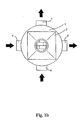
- FIGS 1a to c show a view of the invention from different views Mixer.
- the outer housing is only shown schematically.
- the mixer consists of an outer housing 1 with product inlet 2, product outlet 3 and inlet nozzle 4, 6 and outlet nozzle 5, 7 for the heating / cooling medium and the mixer inserts 8, 10 with inner housing 11,
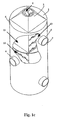
- the internals shown in FIG. 2 are located inside the mixer each made of 90 ° rotated against each other, stacked mixing elements 8, 10, which are separated from one another by separating plates 9 on the temperature medium side to control the flow direction of the temperature control medium. With others Arrangement of the dividers can reduce the number of heating / cooling medium nozzles are accepting a higher pressure drop.
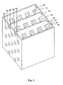
- Figures 3a to c show a mixing element (8) from different views. It consists of the inner housing section 300 and alternating layers of parallel Ridges 301 to 306 or 311 to 317 (in part only recognizable in section in Figure 4). The Bars of two successive layers of bars intersect under one Angle of 90 ° and have an angle of 45 ° to the product flow direction.
- the webs are hollow and have heating / cooling channels 362 to 367 and 371 to 377 (Fig. 4). In order to achieve a flow through the channels, these are through the Layers crossing the webs connecting channels 380, 381, 390, 391, 392 with each other connected (see the section in Fig. 4). From each landing 301 to 306, 311 to 317 only one web 304 or 314 extends from one housing inner wall to the opposite Interior wall. All other webs have a free end.
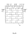
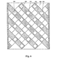
- Figure 5 shows an alternative structure of a mixing element, as in an inventive Mixer can be used.
- On the heating / cooling channels along the Bridges have been dispensed with in favor of simple production, but that is enough Layers of the cross-over cooling channels 580 to 592 through the inner housing of the Mixing element.
- Such a mixing element is particularly suitable for highly viscous products which have the main thermal resistance on the product side and the additional one Thermal resistance due to heat conduction in the now solid webs does not ins Weight drops.
- Figure 6 shows a section through the mixing element of Fig. 5 analogous to the section A-A from Figure 3b.
Landscapes
- Engineering & Computer Science (AREA)
- Chemical & Material Sciences (AREA)
- Physics & Mathematics (AREA)
- Thermal Sciences (AREA)
- Mechanical Engineering (AREA)
- General Engineering & Computer Science (AREA)
- Chemical Kinetics & Catalysis (AREA)
- Dispersion Chemistry (AREA)
- Processing And Handling Of Plastics And Other Materials For Molding In General (AREA)
- Accessories For Mixers (AREA)
- Thermotherapy And Cooling Therapy Devices (AREA)
Description
- Fig. 1a
- die Vorderansicht eines erfindungsgemäßen Mischers
- Fig. 1b
- die Draufsicht auf den Mischer aus Fig. 1a
- Fig. 1c
- die perspektivische Ansicht des Mischers aus Fig. 1a
- Fig. 2
- die perspektivische Ansicht der Einbauten des Mischers aus Fig. 1a
- Fig. 3a
- die Vorderansicht eines Mischelementes des Mischers aus Fig. 1a
- Fig. 3b
- die Draufsicht auf das Mischelement aus Fig. 3a
- Fig. 3c
- die perspektivische Ansicht des Mischelementes aus Fig. 3a
- Fig. 4
- einen Schnitt durch das Mischelement aus Fig. 3a ensprechend der in Fig. 3b eingezeichneten Schnittlinie A-A
- Fig. 5
- die perspektivische Ansicht eines Mischelementes ohne Heiz-/Kühlkanäle in Richtung der Stege
- Fig. 6
- einen Schnitt durch das Mischelement aus Fig. 5 analog zur Schnittlinie A-A aus Fig. 3b
Claims (16)
- Statischer Mischereinsatz (8; 10), bestehend wenigstens aus zwei oder mehreren nebeneinander angeordneten Lagen (a); (b) von insbesondere zu einander parallelen Stegen (501, 502, 503, 504) und (511, 512, 513, 514), wobei sich die Stege jeweils benachbarter Lagen (a); (b) von Stegen (501, 502, 503, 504) bzw. (511, 512, 513, 514) kreuzen und die Stege (501, 502, 503, 504) und (511, 512, 513, 514) an den Kreuzungsstellen miteinander verbunden sind, dadurch gekennzeichnet, daß die Steglagen (a); (b) an den Kreuzungsstellen (320) von Wärmeträgerkanälen (580, 581, 590, 591, 592) durchzogen sind.
- Statischer Mischereinsatz nach Anspruch 1, dadurch gekennzeichnet, daß die Wärmeträgerkanäle (580, 581, 590, 591, 592) in einzelne Zuleitungen und Ableitungen für ein Wärmeträgermedium münden.
- Statischer Mischereinsatz nach Anspruch 1 oder 2, dadurch gekennzeichnet, daß die Stege (501, 502, 503, 504) und (511, 512, 513, 514) wenigstens teilweise als Hohlstege (301, 302, 303, 304, 305, 306, 311, 312, 313, 314, 315, 316, 317) ausgeführt sind, die zusätzliche Kanäle (362, 363, 366, 371, 372, 373, 374, 375, 376, 377) für ein Wärmeträgermedium aufweisen.
- Statischer Mischereinsatz nach einem der Ansprüche 1 bis 3, dadurch gekennzeichnet, daß die Stege (501, 502, 503, 504) und (511, 512, 513, 514) als gerade Stege ausgeführt sind.
- Statischer Mischereinsatz nach Anspruch 4, dadurch gekennzeichnet, daß die Stege (501, 502, 503, 504) bzw. (511, 512, 513, 514) zur Hauptströmungsrichtung des Mischgutes um einen Winkel insbesondere von 30 bis 50° bzw. von -30 bis -50° angestellt sind.
- Statischer Mischereinsatz nach einem der Ansprüche 1 bis 5, dadurch gekennzeichnet, daß die Wärmeträgerkanäle (580, 581, 590, 591, 592) oder die Kanäle (362, 364, 365, 366) mäandrierend an ihren Ein- und Ausgängen miteinander verbunden sind.
- Statischer Mischereinsatz (8; 10), bestehend wenigstens aus zwei oder mehreren nebeneinander angeordneten Lagen (a); (b) von insbesondere zu einander parallelen Stegen (501, 502, 503, 504) und (511, 512, 513, 514), insbesondere mit rechteckigen Querschnitt, wobei sich die Stege jeweils benachbarter Lagen (a); (b) von Stegen (501, 502, 503, 504) bzw. (511, 512, 513, 514) kreuzen und die Stege (501, 502, 503, 504) und (511, 512, 513, 514) an den Kreuzungsstellen miteinander verbunden sind, dadurch gekennzeichnet, daß die Stege (501, 502, 503, 504) und (511, 512, 513, 514) als Hohlstege ausgeführt sind, die Kanäle (362, 364, 365, 366) für ein Wärmeträgermedium aufweisen.
- Statischer Mischereinsatz nach Anspruch 7, dadurch gekennzeichnet, daß die Wärmeträgerkanäle (362, 364, 365, 366) in einzelne Zuleitungen und Ableitungen für ein Wärmeträgermedium münden.
- Statischer Mischereinsatz nach einem der Ansprüche 7 oder 8, dadurch gekennzeichnet, daß die Stege (501, 502, 503, 504) und (511, 512, 513, 514) als gerade Stege ausgeführt sind.
- Statischer Mischereinsatz nach Anspruch 9, dadurch gekennzeichnet, daß die Stege (501, 502, 503, 504) bzw. (511, 512, 513, 514) zur Hauptströmungsrichtung des Mischgutes um einen Winkel insbesondere von 30 bis 50° bzw. von -30 bis -50° angestellt sind.
- Statischer Mischereinsatz nach einem der Ansprüche 7 bis 10, dadurch gekennzeichnet, daß die Wärmeträgerkanäle (362, 364, 365, 366) mäandrierend an ihren Ein- und Ausgängen miteinander verbunden sind.
- Statischer Mischer, bestehend aus wenigstens einem Mischereinsatz (8; 10) nach einem der Ansprüche 1 bis 11 und einem Innengehäuse (11), das den Mischereinsatz (8; 10) umschließt und in dem Öffnungen für die Zuleitung und Ableitung des Wärmeträgermediums zu den Wärmeträgerkanälen (580, 581, 590, 591, 592) oder den Kanälen (362, 364, 365, 366) vorgesehen sind.
- Statischer Mischer nach Anspruch 12, dadurch gekennzeichnet, daß die Wärmeträgerkanäle (580, 581, 590, 591, 592) oder die Kanäle (362, 364, 365, 366) direkt mit den Öffnungen des Innengehäuses verbunden sind.
- Statischer Mischer nach Anspruch 12 oder 13, dadurch gekennzeichnet, daß das Innengehäuse (11) von einem zusätzlichen Außengehäuse (1) umschlossen ist, das wenigstens einen Einlaßstutzen (4, 6) und einen Auslaßstutzen (5, 7) für das Wärmeträgermedium aufweist und mit dem Innengehäuse (11) einen Einlaßraum (12) und einen Auslaßraum (13) für das Wärmeträgermedium bildet und einen Einlaß (2) und einen Auslaß (3) für das Mischgut aufweist.
- Statischer Mischer nach einem der Ansprüche 12 bis 14, dadurch gekennzeichnet, daß mehrere Mischereinsätze (8, 10) in dem Innengehäuse übereinander angeordnet sind und benachbarte Mischereinsätze (8, 10) zueinander um ihre Mittelachse verdreht angeordnet sind.
- Statischer Mischer nach einem der Ansprüche 12 bis 15, dadurch gekennzeichnet, daß jeder Steg einer Steglage bis auf maximal einen Steg nur an einem Ende des Steges an einer Innengehäusewand endet.
Applications Claiming Priority (2)
| Application Number | Priority Date | Filing Date | Title |
|---|---|---|---|
| DE19837671A DE19837671A1 (de) | 1998-08-20 | 1998-08-20 | Statischer Mischer |
| DE19837671 | 1998-08-20 |
Publications (2)
| Publication Number | Publication Date |
|---|---|
| EP0980703A1 EP0980703A1 (de) | 2000-02-23 |
| EP0980703B1 true EP0980703B1 (de) | 2003-05-14 |
Family
ID=7878058
Family Applications (1)
| Application Number | Title | Priority Date | Filing Date |
|---|---|---|---|
| EP99115110A Expired - Lifetime EP0980703B1 (de) | 1998-08-20 | 1999-08-09 | Statischer Mischer |
Country Status (5)
| Country | Link |
|---|---|
| US (1) | US6412975B1 (de) |
| EP (1) | EP0980703B1 (de) |
| JP (1) | JP4074413B2 (de) |
| CA (1) | CA2280469C (de) |
| DE (2) | DE19837671A1 (de) |
Cited By (1)
| Publication number | Priority date | Publication date | Assignee | Title |
|---|---|---|---|---|
| EP1125625A2 (de) | 2000-02-18 | 2001-08-22 | Schröder & Boos, Misch- und Anlagentechnik GmbH & Co. KG | Homogenisator |
Families Citing this family (17)
| Publication number | Priority date | Publication date | Assignee | Title |
|---|---|---|---|---|
| DE10005457A1 (de) * | 2000-02-08 | 2001-08-09 | Bayer Ag | Statischer Mischer |
| JP2003181256A (ja) * | 2001-12-17 | 2003-07-02 | Art Ceramic Kk | 静止型混合器及びその静止型混合器用部品 |
| DE10233506B4 (de) * | 2002-07-24 | 2004-12-09 | Bayer Technology Services Gmbh | Mischer/Wärmeaustauscher |
| CA2617731A1 (en) * | 2007-01-12 | 2008-07-12 | Superior Quilting Limited | Thermal controlled pillow |
| TWI404903B (zh) * | 2007-03-09 | 2013-08-11 | Sulzer Chemtech Ag | 用於流體媒介物熱交換及混合處理之設備 |
| DE102009033661A1 (de) | 2009-07-17 | 2011-01-20 | Bayer Technology Services Gmbh | Wärmeübertragermodul und Wärmeübertrager in kompakter Bauweise |
| US9777973B2 (en) * | 2013-09-20 | 2017-10-03 | Promix Solutions Ag | Device for mixing and heat exchange |
| US20150087733A1 (en) | 2013-09-20 | 2015-03-26 | Rolf Heusser | Method for the Manufacture of Foams of Low Density |
| EP3374070B1 (de) | 2015-11-13 | 2023-08-09 | Re Mixers, Inc. | Statischer mischer |
| US9839883B2 (en) * | 2016-03-18 | 2017-12-12 | Komax Systems, Inc. | Channel mixing apparatus |
| CN114761112B (zh) | 2019-10-21 | 2024-08-13 | 雷米克瑟斯公司 | 静态混合器 |
| US12104865B2 (en) * | 2019-11-14 | 2024-10-01 | Promix Solutions Ag | Heat exchanger |
| US20210293483A1 (en) * | 2020-03-23 | 2021-09-23 | General Electric Company | Multifurcating heat exchanger with independent baffles |
| US11365681B2 (en) * | 2020-04-23 | 2022-06-21 | Raytheon Technologies Corporation | Plumbing with internal flow guides |
| EP4089357B1 (de) * | 2021-05-10 | 2025-09-03 | Promix Solutions AG | Wärmetauscher |
| CN118434784A (zh) | 2021-12-20 | 2024-08-02 | 巴斯夫涂料有限公司 | 水性聚氨酯分散体的连续生产方法 |
| DE102024113494B3 (de) * | 2024-05-14 | 2025-11-06 | INEXCO Europe GmbH | Vorrichtung zum Mischen und Kühlen von Medien in einem Extruder und Mischkühleranordnung umfassend eine Mehrzahl von solchen Vorrichtungen |
Family Cites Families (14)
| Publication number | Priority date | Publication date | Assignee | Title |
|---|---|---|---|---|
| US1436379A (en) * | 1920-10-29 | 1922-11-21 | Joseph Goodfellow | Superheater |
| US1655971A (en) * | 1927-06-09 | 1928-01-10 | Clarence W Pflug | Automobile radiator core |
| US2809018A (en) * | 1951-11-15 | 1957-10-08 | Ekstroems Maskinaffaer Ab | Apparatus for distributing cleaning particles over gas-swept surfaces in heat exchangers and the like |
| US2839275A (en) * | 1954-10-26 | 1958-06-17 | United Aircraft Corp | Heat exchanger |
| US2877000A (en) * | 1955-09-16 | 1959-03-10 | Int Harvester Co | Heat exchanger |
| US3240268A (en) * | 1962-01-02 | 1966-03-15 | Gen Motors Corp | Stacked caseless heat exchangers |
| GB1292365A (en) * | 1969-05-23 | 1972-10-11 | Windmoeller & Hoelscher | Mixing devices for plastics materials |
| CH537208A (de) * | 1971-04-29 | 1973-07-13 | Sulzer Ag | Mischeinrichtung für fliessfähige Medien |
| US4062524A (en) | 1973-06-06 | 1977-12-13 | Bayer Aktiengesellschaft | Apparatus for the static mixing of fluid streams |
| DE2839564C2 (de) | 1978-09-12 | 1982-10-21 | Hoechst Ag, 6000 Frankfurt | Vorrichtung mit Zu- und Abfuhr von Wärme und zum Mischen von flüssigen Medien |
| DE3136589A1 (de) | 1981-09-15 | 1983-03-31 | Bayer Ag | Temperierbarer statischer mischer und reaktor |
| US4488920A (en) * | 1982-05-18 | 1984-12-18 | Williams International Corporation | Process of making a ceramic heat exchanger element |
| US4865460A (en) | 1988-05-02 | 1989-09-12 | Kama Corporation | Static mixing device |
| DE4416343C2 (de) | 1994-05-09 | 1996-10-17 | Karlsruhe Forschzent | Statischer Mikro-Vermischer |
-
1998
- 1998-08-20 DE DE19837671A patent/DE19837671A1/de not_active Withdrawn
-
1999
- 1999-08-05 US US09/369,212 patent/US6412975B1/en not_active Expired - Fee Related
- 1999-08-09 DE DE59905535T patent/DE59905535D1/de not_active Expired - Lifetime
- 1999-08-09 EP EP99115110A patent/EP0980703B1/de not_active Expired - Lifetime
- 1999-08-13 JP JP22929699A patent/JP4074413B2/ja not_active Expired - Fee Related
- 1999-08-17 CA CA002280469A patent/CA2280469C/en not_active Expired - Fee Related
Cited By (1)
| Publication number | Priority date | Publication date | Assignee | Title |
|---|---|---|---|---|
| EP1125625A2 (de) | 2000-02-18 | 2001-08-22 | Schröder & Boos, Misch- und Anlagentechnik GmbH & Co. KG | Homogenisator |
Also Published As
| Publication number | Publication date |
|---|---|
| JP2000135424A (ja) | 2000-05-16 |
| US6412975B1 (en) | 2002-07-02 |
| DE19837671A1 (de) | 2000-02-24 |
| DE59905535D1 (de) | 2003-06-18 |
| EP0980703A1 (de) | 2000-02-23 |
| JP4074413B2 (ja) | 2008-04-09 |
| CA2280469A1 (en) | 2000-02-20 |
| CA2280469C (en) | 2006-10-24 |
Similar Documents
| Publication | Publication Date | Title |
|---|---|---|
| EP0980703B1 (de) | Statischer Mischer | |
| EP1123730B1 (de) | Statischer Mischer | |
| EP3585509B1 (de) | Wärmeübertrager und reaktor | |
| EP1216747B1 (de) | Statischer Mischer | |
| EP0967004A1 (de) | Statische Mischvorrichtung | |
| EP2851118A1 (de) | Vorrichtung zum Mischen und zum Wärmetausch und Verfahren zu seiner Herstellung | |
| EP3408014A1 (de) | Hohlraum-x-mischer-wärmetauscher | |
| DE112004001604B4 (de) | Dreidimensionale quer angeordnete Umlenkeinrichtung als inneres Element in einem Rohr, einem Fass oder einem Turm | |
| EP3822569B1 (de) | Wärmetauscher | |
| EP1800079A1 (de) | Wärmetauscher | |
| EP3966513B1 (de) | Rohrbündel-wärmeübertrager mit baugruppen/einbauelementen aus umlenkflächen und leitstegen | |
| EP4089357B1 (de) | Wärmetauscher | |
| DE2736510A1 (de) | Waermeaustauscher | |
| EP1139055A2 (de) | Mehrfachrohrbündel-Wärmeaustauscher | |
| EP0177904A2 (de) | Vorrichtung zum Austausch der Wärme zwischen zwei im Kreuzstrom zueinander geführten Gasen | |
| DE931595C (de) | Gegenstrom-Waermeaustauscher | |
| EP2936030A1 (de) | Wärmeübertrager | |
| EP2069703B1 (de) | Wärmetauscher | |
| DE1601151A1 (de) | Plattenwaermetauscher | |
| DE102019009099A1 (de) | Wärmetauscher mit Mischfunktion | |
| EP1052468A2 (de) | Plattenwärmetauscher, insbesondere Ölkühler | |
| CH641893A5 (en) | Heat exchanger element, method for producing it, and a heat exchanger | |
| AT212859B (de) | Wärmetauscher | |
| DE10048016C1 (de) | Gegenstrom-Wärmetauscher | |
| WO2016012514A2 (de) | Wärmeübertrager und baukastensystem zur herstellung eines wärmeübertragers |
Legal Events
| Date | Code | Title | Description |
|---|---|---|---|
| PUAI | Public reference made under article 153(3) epc to a published international application that has entered the european phase |
Free format text: ORIGINAL CODE: 0009012 |
|
| AK | Designated contracting states |
Kind code of ref document: A1 Designated state(s): CH DE FR GB IT LI |
|
| AX | Request for extension of the european patent |
Free format text: AL;LT;LV;MK;RO;SI |
|
| 17P | Request for examination filed |
Effective date: 20000823 |
|
| AKX | Designation fees paid |
Free format text: CH DE FR GB IT LI |
|
| GRAH | Despatch of communication of intention to grant a patent |
Free format text: ORIGINAL CODE: EPIDOS IGRA |
|
| GRAH | Despatch of communication of intention to grant a patent |
Free format text: ORIGINAL CODE: EPIDOS IGRA |
|
| GRAA | (expected) grant |
Free format text: ORIGINAL CODE: 0009210 |
|
| AK | Designated contracting states |
Designated state(s): CH DE FR GB IT LI |
|
| REG | Reference to a national code |
Ref country code: GB Ref legal event code: FG4D Free format text: NOT ENGLISH |
|
| REG | Reference to a national code |
Ref country code: CH Ref legal event code: EP |
|
| REG | Reference to a national code |
Ref country code: CH Ref legal event code: NV Representative=s name: E. BLUM & CO. PATENTANWAELTE |
|
| REF | Corresponds to: |
Ref document number: 59905535 Country of ref document: DE Date of ref document: 20030618 Kind code of ref document: P |
|
| GBT | Gb: translation of ep patent filed (gb section 77(6)(a)/1977) |
Effective date: 20030722 |
|
| ET | Fr: translation filed | ||
| PLBE | No opposition filed within time limit |
Free format text: ORIGINAL CODE: 0009261 |
|
| STAA | Information on the status of an ep patent application or granted ep patent |
Free format text: STATUS: NO OPPOSITION FILED WITHIN TIME LIMIT |
|
| 26N | No opposition filed |
Effective date: 20040217 |
|
| REG | Reference to a national code |
Ref country code: CH Ref legal event code: PFA Owner name: BAYER AKTIENGESELLSCHAFT Free format text: BAYER AKTIENGESELLSCHAFT# #51368 LEVERKUSEN (DE) -TRANSFER TO- BAYER AKTIENGESELLSCHAFT# #51368 LEVERKUSEN (DE) |
|
| REG | Reference to a national code |
Ref country code: FR Ref legal event code: TP Owner name: BAYER INTELLECTUAL PROPERTY GMBH, DE Effective date: 20130109 |
|
| REG | Reference to a national code |
Ref country code: DE Ref legal event code: R081 Ref document number: 59905535 Country of ref document: DE Owner name: BAYER INTELLECTUAL PROPERTY GMBH, DE Free format text: FORMER OWNER: BAYER TECHNOLOGY SERVICES GMBH, 51373 LEVERKUSEN, DE Effective date: 20130226 |
|
| REG | Reference to a national code |
Ref country code: CH Ref legal event code: PUE Owner name: BAYER INTELLECTUAL PROPERTY GMBH, DE Free format text: FORMER OWNER: BAYER AKTIENGESELLSCHAFT, DE |
|
| PGFP | Annual fee paid to national office [announced via postgrant information from national office to epo] |
Ref country code: DE Payment date: 20130807 Year of fee payment: 15 Ref country code: CH Payment date: 20130813 Year of fee payment: 15 |
|
| PGFP | Annual fee paid to national office [announced via postgrant information from national office to epo] |
Ref country code: GB Payment date: 20130807 Year of fee payment: 15 Ref country code: FR Payment date: 20130808 Year of fee payment: 15 |
|
| PGFP | Annual fee paid to national office [announced via postgrant information from national office to epo] |
Ref country code: IT Payment date: 20130725 Year of fee payment: 15 |
|
| REG | Reference to a national code |
Ref country code: DE Ref legal event code: R119 Ref document number: 59905535 Country of ref document: DE |
|
| REG | Reference to a national code |
Ref country code: CH Ref legal event code: PL |
|
| GBPC | Gb: european patent ceased through non-payment of renewal fee |
Effective date: 20140809 |
|
| PG25 | Lapsed in a contracting state [announced via postgrant information from national office to epo] |
Ref country code: IT Free format text: LAPSE BECAUSE OF NON-PAYMENT OF DUE FEES Effective date: 20140809 Ref country code: CH Free format text: LAPSE BECAUSE OF NON-PAYMENT OF DUE FEES Effective date: 20140831 Ref country code: LI Free format text: LAPSE BECAUSE OF NON-PAYMENT OF DUE FEES Effective date: 20140831 |
|
| REG | Reference to a national code |
Ref country code: FR Ref legal event code: ST Effective date: 20150430 |
|
| REG | Reference to a national code |
Ref country code: DE Ref legal event code: R119 Ref document number: 59905535 Country of ref document: DE Effective date: 20150303 |
|
| PG25 | Lapsed in a contracting state [announced via postgrant information from national office to epo] |
Ref country code: DE Free format text: LAPSE BECAUSE OF NON-PAYMENT OF DUE FEES Effective date: 20150303 Ref country code: GB Free format text: LAPSE BECAUSE OF NON-PAYMENT OF DUE FEES Effective date: 20140809 |
|
| PG25 | Lapsed in a contracting state [announced via postgrant information from national office to epo] |
Ref country code: FR Free format text: LAPSE BECAUSE OF NON-PAYMENT OF DUE FEES Effective date: 20140901 |