EP0979918A2 - Gerät zur Feststellung von Hindernissen - Google Patents
Gerät zur Feststellung von Hindernissen Download PDFInfo
- Publication number
- EP0979918A2 EP0979918A2 EP99305211A EP99305211A EP0979918A2 EP 0979918 A2 EP0979918 A2 EP 0979918A2 EP 99305211 A EP99305211 A EP 99305211A EP 99305211 A EP99305211 A EP 99305211A EP 0979918 A2 EP0979918 A2 EP 0979918A2
- Authority
- EP
- European Patent Office
- Prior art keywords
- strips
- electrical
- window
- conductive strips
- conductive
- Prior art date
- Legal status (The legal status is an assumption and is not a legal conclusion. Google has not performed a legal analysis and makes no representation as to the accuracy of the status listed.)
- Granted
Links
- 239000013536 elastomeric material Substances 0.000 claims abstract description 10
- 239000000853 adhesive Substances 0.000 claims abstract description 5
- 230000001070 adhesive effect Effects 0.000 claims abstract description 5
- 238000002347 injection Methods 0.000 claims abstract description 3
- 239000007924 injection Substances 0.000 claims abstract description 3
- 239000000463 material Substances 0.000 claims description 33
- 239000005357 flat glass Substances 0.000 claims description 12
- 229910052751 metal Inorganic materials 0.000 claims description 8
- 239000002184 metal Substances 0.000 claims description 7
- 239000004020 conductor Substances 0.000 claims description 5
- 238000001514 detection method Methods 0.000 claims description 5
- 239000012858 resilient material Substances 0.000 claims description 3
- 238000000034 method Methods 0.000 abstract description 3
- 238000005476 soldering Methods 0.000 abstract description 2
- 238000010586 diagram Methods 0.000 description 2
- 238000001125 extrusion Methods 0.000 description 2
- 239000011521 glass Substances 0.000 description 2
- 229910000831 Steel Inorganic materials 0.000 description 1
- 208000027418 Wounds and injury Diseases 0.000 description 1
- 239000004411 aluminium Substances 0.000 description 1
- 229910052782 aluminium Inorganic materials 0.000 description 1
- XAGFODPZIPBFFR-UHFFFAOYSA-N aluminium Chemical compound [Al] XAGFODPZIPBFFR-UHFFFAOYSA-N 0.000 description 1
- 230000006378 damage Effects 0.000 description 1
- 239000003000 extruded plastic Substances 0.000 description 1
- 244000144992 flock Species 0.000 description 1
- 208000014674 injury Diseases 0.000 description 1
- 239000011810 insulating material Substances 0.000 description 1
- 239000000615 nonconductor Substances 0.000 description 1
- 239000002245 particle Substances 0.000 description 1
- 230000000630 rising effect Effects 0.000 description 1
- 238000007789 sealing Methods 0.000 description 1
- 239000010959 steel Substances 0.000 description 1
- 238000005728 strengthening Methods 0.000 description 1
Images


Classifications
-
- B—PERFORMING OPERATIONS; TRANSPORTING
- B60—VEHICLES IN GENERAL
- B60J—WINDOWS, WINDSCREENS, NON-FIXED ROOFS, DOORS, OR SIMILAR DEVICES FOR VEHICLES; REMOVABLE EXTERNAL PROTECTIVE COVERINGS SPECIALLY ADAPTED FOR VEHICLES
- B60J10/00—Sealing arrangements
-
- B—PERFORMING OPERATIONS; TRANSPORTING
- B60—VEHICLES IN GENERAL
- B60J—WINDOWS, WINDSCREENS, NON-FIXED ROOFS, DOORS, OR SIMILAR DEVICES FOR VEHICLES; REMOVABLE EXTERNAL PROTECTIVE COVERINGS SPECIALLY ADAPTED FOR VEHICLES
- B60J10/00—Sealing arrangements
- B60J10/80—Sealing arrangements specially adapted for opening panels, e.g. doors
- B60J10/86—Sealing arrangements specially adapted for opening panels, e.g. doors arranged on the opening panel
- B60J10/88—Sealing arrangements specially adapted for opening panels, e.g. doors arranged on the opening panel mounted on, or integral with, the glass-run seals
-
- E—FIXED CONSTRUCTIONS
- E05—LOCKS; KEYS; WINDOW OR DOOR FITTINGS; SAFES
- E05F—DEVICES FOR MOVING WINGS INTO OPEN OR CLOSED POSITION; CHECKS FOR WINGS; WING FITTINGS NOT OTHERWISE PROVIDED FOR, CONCERNED WITH THE FUNCTIONING OF THE WING
- E05F15/00—Power-operated mechanisms for wings
- E05F15/40—Safety devices, e.g. detection of obstructions or end positions
- E05F15/42—Detection using safety edges
- E05F15/44—Detection using safety edges responsive to changes in electrical conductivity
- E05F15/443—Detection using safety edges responsive to changes in electrical conductivity specially adapted for vehicle windows or roofs
-
- E—FIXED CONSTRUCTIONS
- E05—LOCKS; KEYS; WINDOW OR DOOR FITTINGS; SAFES
- E05Y—INDEXING SCHEME ASSOCIATED WITH SUBCLASSES E05D AND E05F, RELATING TO CONSTRUCTION ELEMENTS, ELECTRIC CONTROL, POWER SUPPLY, POWER SIGNAL OR TRANSMISSION, USER INTERFACES, MOUNTING OR COUPLING, DETAILS, ACCESSORIES, AUXILIARY OPERATIONS NOT OTHERWISE PROVIDED FOR, APPLICATION THEREOF
- E05Y2900/00—Application of doors, windows, wings or fittings thereof
- E05Y2900/50—Application of doors, windows, wings or fittings thereof for vehicles
- E05Y2900/53—Type of wing
- E05Y2900/55—Windows
Definitions
- the invention relates to apparatus responsive to an obstruction in the path of movement of a slidable member, comprising first and second normally spaced-apart strips of electrically conductive resilient material, means for mounting the strips adjacent to the path such that an obstruction in the path is moved by the slidable member towards the conductive strips and causes them to be brought into contact at a corresponding point along their lengths, and control means operative to electrically sense such contact whereby to detect the obstruction and to produce a detection signal.
- Such apparatus is shown, for example, in EP-A-0 638 701. It is desirable, however, to be able to detect any electrical discontinuity in either of the strips so as to give a warning that the apparatus is faulty.
- the apparatus as first set forth above is characterised by electrical resistance means interconnecting the two electrically conductive strips at a predetermined position whereby to allow a predetermined electrical current to flow through the strips when they are separated so that occurrence of an electrical discontinuity in either of the strips interrupts this current to produce a fault signal, the electrical resistance means comprising treated elastomeric material.
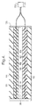
- Figure 1 shows a motor vehicle 5 having a front door 6 with a power-driven window 8 which is shown cross-hatched for clarity.
- the power-driven window 8 is raised and lowered by means of a suitable motor, normally an electric motor, under the control of switches positioned within the vehicle for use by the drive or passenger. All or some of the other side windows in the vehicle may also be power-driven.
- the window frame 10, forming part of the vehicle door 5, is, in this example, made of metal and comprises a portion 10A (Fig. 1) running adjacent to the "A" pillar of the vehicle body (when the door 6 is closed), a portion 10B running alongside the "B" pillar, and a portion 10C running along the top of the door.
- the window frame incorporates a window seal 12.
- the form which the seal 12 takes over the frame portions 10A and 10C is shown in Figure 2.
- the seal 12 is supported so that it provides a channel 14 into and out of which the window glass 8 slides as it is raised and lowered.
- the window channel strip 12 is made of extruded plastics or rubber material 16 and incorporates an embedded metal core or carrier 18.
- the carrier 18 may take any suitable form.
- it may comprise a simple channel of metal.
- the channel could additionally be formed with apertures to increase its flexibility.
- the carrier could be made from U-shaped metal elements arranged side-by-side to define the channel and either connected together by short flexible interconnecting links or entirely disconnected from each other.
- the metal could be steel or aluminium, for example.
- the carrier could be made of metal wire looped to and fro to define the channel of the carrier.
- the carrier 18 is preferably incorporated into the extruded material 16 by a known cross-head extrusion process.
- the carrier 18 embraces a secondary channel 20 formed in the extruded material 16, and the material 16 forming the channel 20 embraces a flange 22 formed where the sheet material constituting the window frame 10 is bent over on itself and the two edges welded together.
- the extruded material is extruded to define lips 24 and shoulders 26 which make frictional contact with the sides of the flange 22 and, in conjunction with the resilience of the metal carrier 18, ensure that the window channel strip 12 is firmly fixed to the window frame 10.
- the extruded material forming the lips 24 and shoulders 26 is relatively soft and may be softer than the remainder of the extruded material. The softness of the material of the lips 24 and shoulders 26 helps to increase the force with which they grip the flange 22.
- the carrier 18 advantageously has an integral extension 28 into part of the material defining one of the side walls of the window channel 14, to provide additional strengthening.
- the extruded material 16 also defines a rib 30 having a projecting ridge 32 and a groove 34 which fits over a shoulder 36 formed in the material of the frame 10.
- the groove 34 and the shoulder 36 help to locate the window channel strip 12 in position in the window frame.
- the window glass receiving channel 14 is defined by an outer wall portion 38 and has integral lips 40 and 42 for making contact with the edge and side of the window glass 8.
- the surfaces of the material 16 which make contact with the glass 8 are advantageously covered with flock or similar material to provide low mechanical resistance to movement of the glass and also good sealing.
- the wall 44 of the window glass receiving channel 14 may be provided with a cavity 46 to increase the flexibility of the material defining the window channel.
- the material 16 also defines a large lip 50 which is shaped to lie closely against the downwardly facing surface 52 of the window frame 10C.
- the lip 50 is made of electrially insulating material. If the extruded material 16 is electrically insulating, then the lip 50 can be of the same type of material as the rest of the material. If the material 16 is not a good electrical insulator, the material of the lip 50 will be arranged to be different so as to have sufficient electrically insulating properties. Normally, though, the material of the lip 50 would be co-extruded with the remainder of the material 16.
- the material of the lip 50 is extruded so as to define an interior cavity indicated generally at 54.
- This cavity provides two recesses 56 and 58 which are each generally rectangular in cross-section and extend longitudinally along the length of the lip 50 (which itself extends along the portions 10A and 10C of the window frame).
- a strip of electrically conductive material (rubber for preference) 60,62 is mounted so as to be a secure fit.
- the strips 60,62 may be secured in position by means of adhesive. Instead, however, they can be co-extruded with the remainder of the material 16 and of the lip 50.
- the strips of material 60,62 are sized to provide a gap 64 between them and extending within the cavity 54.
- Electrically conductive wires 66,68 are respectively embedded within the strips 60,62 of electrically conductive material. These wires extend for substantially the full length of the strips 60,62. These may be incorporated during the extrusion process described above.
- Figure 3 shows a schematic circuit diagram of one form of the system.
- Figure 3 shows positive and negative supply lines 70 and 72 of the vehicle's electrical supply and which are energised by the vehicle's battery (not shown).
- electric motor 74 is provided for raising and lowering the window glass 8.
- the motor has a supply line 76 which is energised to drive the motor in a window-raising direction and a supply line 78 which is energised to drive the motor in a window-lowering direction.
- Lines 76 and 78 are energised from the positive supply line 70 by means of a driver or passenger operated manual switch 80.
- switch 80 When switch 80 is set in a raising direction, an output 82 is energised and in turn energises line 76 through a normally closed switching unit 84, and the window is raised by the motor.
- switch 80 When switch 80 is set in the lowering direction, an output 86 is energised which is directly connected to line 78, and the window glass is lowered by the motor.
- Figure 3 diagrammatically shows the strips of conductive rubber 60 and 62 (Fig. 2) which are separated by the gap 64 of the cavity 54.
- the embedded electrically conductive wires 66 and 68 are also shown.
- wire 68 is connected to the positive supply line 70 through a resistor 87.
- the junction between resistor 87 and one end of wire 68 is connected to a control unit 88 by a line 89, the control unit also being itself connected to the positive and negative supply rails 70,72 for energisation thereby.
- One end of wire 66 is connected to the negatie supply line 72 by a line 90.
- a resistor 91 is connected to the opposite ends of the wires 66,68.
- Resistors 87 and 91 have high values. In the situation illustrated in Figure 3, with the conductive strips 60,62 separated, a small current flows through these resistors and through the conductive rubber strips 60, 62 and the embedded wires 66 and 68.
- control unit 88 may energise a line 94 which closes a second switching unit 96. This energises line 78 to drive the motor 74 in the window-lowering direction (thus releasing the trapped object).
- the wires 66 and 68 can be omitted. In that case, the electrical connections to the wires 66,68 as shown in Figure 3 would instead be made directly to the conductive strips.
- Figure 4 shows how the two conductive strips 60,62 with their embedded wires 66,68, can be produced as a unit, together with the resistor 91.
- the resistor 91 is formed from rubber or other elastomeric material which is treated so as to have the required electrical resistance, such as by incorporating conductive material, in the form of conductive particles for example.
- the electrical resistance of the material can be adjusted to the desired value by altering its length and/or geometry, as well, of course, as by adjusting the specific resistance of the material.
- the rubber forming the resistor 91 is secured in position by injection, by adhesive (using electrially conductive adhesive) or by clamping or in any other suitable way.
- Adjustments to the value of the resistor 91 can be made after fitting the resistor in position, by grinding the material of the resistor. As shown in Figure 4, the opposite ends of the chamber 64 can be closed off by non-conductive end caps 98,100. A plug 102 is used to make the connections to the remainder of the circuitry.
- treated elastomeric material to form the resistor 91 is advantageous because it can be secured in position very simply in the ways described, and thus eliminates the need for a difficult and uneconomic soldering operation if a wired resistor is used.
Landscapes
- Engineering & Computer Science (AREA)
- Mechanical Engineering (AREA)
- Window Of Vehicle (AREA)
Applications Claiming Priority (2)
| Application Number | Priority Date | Filing Date | Title |
|---|---|---|---|
| GB9817286A GB2340662B (en) | 1998-08-07 | 1998-08-07 | Obstruction-responsive apparatus |
| GB9817286 | 1998-08-07 |
Publications (3)
| Publication Number | Publication Date |
|---|---|
| EP0979918A2 true EP0979918A2 (de) | 2000-02-16 |
| EP0979918A3 EP0979918A3 (de) | 2000-03-29 |
| EP0979918B1 EP0979918B1 (de) | 2005-01-12 |
Family
ID=10836929
Family Applications (1)
| Application Number | Title | Priority Date | Filing Date |
|---|---|---|---|
| EP99305211A Expired - Lifetime EP0979918B1 (de) | 1998-08-07 | 1999-07-01 | Gerät zur Feststellung von Hindernissen |
Country Status (3)
| Country | Link |
|---|---|
| EP (1) | EP0979918B1 (de) |
| DE (1) | DE69923122T2 (de) |
| GB (1) | GB2340662B (de) |
Cited By (1)
| Publication number | Priority date | Publication date | Assignee | Title |
|---|---|---|---|---|
| US10487570B1 (en) | 2018-07-05 | 2019-11-26 | Schlage Lock Company Llc | Door with interior protective coating |
Families Citing this family (5)
| Publication number | Priority date | Publication date | Assignee | Title |
|---|---|---|---|---|
| DE10310066B3 (de) | 2003-03-07 | 2005-02-17 | Metzeler Automotive Profile Systems Gmbh | Vorrichtung zum Erkennen eines Hindernisses in dem Öffnungsbereich eines bewegbaren Schließelements |
| GB0603247D0 (en) * | 2006-02-17 | 2006-03-29 | Gdx North America Inc | Vehicle opening device |
| GB2435517A (en) * | 2006-02-17 | 2007-08-29 | Gdx North America Inc | Vehicle opening sensor device |
| GB2435516A (en) * | 2006-02-17 | 2007-08-29 | Gdx North America Inc | Vehicle object sensing assembly |
| JP2022048796A (ja) * | 2020-09-15 | 2022-03-28 | 株式会社ハイレックスコーポレーション | 感圧式タッチセンサ及び車両用ドアシステム |
Citations (1)
| Publication number | Priority date | Publication date | Assignee | Title |
|---|---|---|---|---|
| EP0638701A2 (de) | 1993-08-09 | 1995-02-15 | METZELER Automotive Profiles GmbH | Einklemmschutz für kraftbetätigte Schliesseinrichtungen |
Family Cites Families (5)
| Publication number | Priority date | Publication date | Assignee | Title |
|---|---|---|---|---|
| DE2644608C3 (de) * | 1976-10-02 | 1981-05-27 | Erwin Sick Gmbh Optik-Elektronik, 7808 Waldkirch | Schutzeinrichtung an einer Schließkante |
| DE3206466A1 (de) * | 1982-02-23 | 1983-09-01 | Preh, Elektrofeinmechanische Werke, Jakob Preh, Nachf. Gmbh & Co, 8740 Bad Neustadt | Sicherheitseinrichtung fuer kraftfahrzeugfenster |
| DE3809960A1 (de) * | 1988-03-24 | 1989-10-05 | Bosch Gmbh Robert | Einklemmschutz-sensor |
| GB2304458B (en) * | 1995-08-19 | 1999-02-24 | Rover Group | A detection system |
| DE19602744C2 (de) * | 1996-01-19 | 1999-04-29 | Mayser Gmbh & Co | Sicherheitsschaltleistenanordnung |
-
1998
- 1998-08-07 GB GB9817286A patent/GB2340662B/en not_active Expired - Fee Related
-
1999
- 1999-07-01 EP EP99305211A patent/EP0979918B1/de not_active Expired - Lifetime
- 1999-07-01 DE DE69923122T patent/DE69923122T2/de not_active Expired - Fee Related
Patent Citations (1)
| Publication number | Priority date | Publication date | Assignee | Title |
|---|---|---|---|---|
| EP0638701A2 (de) | 1993-08-09 | 1995-02-15 | METZELER Automotive Profiles GmbH | Einklemmschutz für kraftbetätigte Schliesseinrichtungen |
Cited By (1)
| Publication number | Priority date | Publication date | Assignee | Title |
|---|---|---|---|---|
| US10487570B1 (en) | 2018-07-05 | 2019-11-26 | Schlage Lock Company Llc | Door with interior protective coating |
Also Published As
| Publication number | Publication date |
|---|---|
| GB2340662A (en) | 2000-02-23 |
| EP0979918B1 (de) | 2005-01-12 |
| DE69923122T2 (de) | 2005-06-16 |
| GB9817286D0 (en) | 1998-10-07 |
| DE69923122D1 (de) | 2005-02-17 |
| EP0979918A3 (de) | 2000-03-29 |
| GB2340662B (en) | 2002-04-17 |
Similar Documents
| Publication | Publication Date | Title |
|---|---|---|
| AU671906B2 (en) | Trapping protector for power-operated closing devices | |
| US7215529B2 (en) | Capacitive sensor having flexible polymeric conductors | |
| EP1154110B2 (de) | Einklemmschutz | |
| US5438798A (en) | Safety edge assembly for a movable closure | |
| JP5126271B2 (ja) | 長尺センサ | |
| EP0979918B1 (de) | Gerät zur Feststellung von Hindernissen | |
| EP0648628B1 (de) | Sicherheitsgerät für ein bewegbares Fenster | |
| WO2007093910A2 (en) | Vehicle opening device | |
| US12065023B2 (en) | Vehicular rear slider window assembly with retaining element | |
| US5834719A (en) | Cord switch | |
| WO2007093914A1 (en) | Portable object sensing assembly | |
| EP0015393A1 (de) | Motorische Betätigungsvorrichtung zum Öffnen und Schliessen verschiebbarer Fahrzeugfenster | |
| US20120153972A1 (en) | Vehicle opening device | |
| WO2007093912A1 (en) | Vehicle opening device | |
| GB2293207A (en) | A window seal | |
| JPH09264094A (ja) | 車両用スライドドアの開閉検出装置および開閉装置 | |
| CN110239322A (zh) | 车窗密封条和车辆 | |
| WO1994008119A1 (en) | Safety edge switch system | |
| GB2319294A (en) | Vehicle window:safety control | |
| US20180148968A1 (en) | Obstruction detection device | |
| CN223724406U (zh) | 防夹条、车门防夹装置、车门和车辆 | |
| EP0799736A1 (de) | Dichtungs-und Führungsleisten und Sicherheitssystem für motorisch angetriebeneFahrzeugfenster | |
| JP3735998B2 (ja) | 動力付窓開閉装置 | |
| KR100439909B1 (ko) | 자동차의 전동식 도어 윈도 레귤레이터용 장애물 감지 기구 | |
| CN113250573A (zh) | 具有牢固地整合在空心型材的腔室中的用电工作的开关板条的能弹性弯曲的空心型材 |
Legal Events
| Date | Code | Title | Description |
|---|---|---|---|
| PUAI | Public reference made under article 153(3) epc to a published international application that has entered the european phase |
Free format text: ORIGINAL CODE: 0009012 |
|
| PUAL | Search report despatched |
Free format text: ORIGINAL CODE: 0009013 |
|
| AK | Designated contracting states |
Kind code of ref document: A2 Designated state(s): DE ES FR IT |
|
| AX | Request for extension of the european patent |
Free format text: AL;LT;LV;MK;RO;SI |
|
| AK | Designated contracting states |
Kind code of ref document: A3 Designated state(s): AT BE CH CY DE DK ES FI FR GB GR IE IT LI LU MC NL PT SE |
|
| AX | Request for extension of the european patent |
Free format text: AL;LT;LV;MK;RO;SI |
|
| 17P | Request for examination filed |
Effective date: 20000719 |
|
| AKX | Designation fees paid |
Free format text: DE ES FR IT |
|
| RAP1 | Party data changed (applicant data changed or rights of an application transferred) |
Owner name: GENCORP PROPERTY INC. |
|
| 17Q | First examination report despatched |
Effective date: 20020125 |
|
| GRAP | Despatch of communication of intention to grant a patent |
Free format text: ORIGINAL CODE: EPIDOSNIGR1 |
|
| GRAS | Grant fee paid |
Free format text: ORIGINAL CODE: EPIDOSNIGR3 |
|
| GRAA | (expected) grant |
Free format text: ORIGINAL CODE: 0009210 |
|
| RAP1 | Party data changed (applicant data changed or rights of an application transferred) |
Owner name: GDX NORTH AMERICA INC. |
|
| AK | Designated contracting states |
Kind code of ref document: B1 Designated state(s): DE ES FR IT |
|
| PG25 | Lapsed in a contracting state [announced via postgrant information from national office to epo] |
Ref country code: IT Free format text: LAPSE BECAUSE OF FAILURE TO SUBMIT A TRANSLATION OF THE DESCRIPTION OR TO PAY THE FEE WITHIN THE PRESCRIBED TIME-LIMIT;WARNING: LAPSES OF ITALIAN PATENTS WITH EFFECTIVE DATE BEFORE 2007 MAY HAVE OCCURRED AT ANY TIME BEFORE 2007. THE CORRECT EFFECTIVE DATE MAY BE DIFFERENT FROM THE ONE RECORDED. Effective date: 20050112 Ref country code: FR Free format text: LAPSE BECAUSE OF NON-PAYMENT OF DUE FEES Effective date: 20050112 |
|
| REF | Corresponds to: |
Ref document number: 69923122 Country of ref document: DE Date of ref document: 20050217 Kind code of ref document: P |
|
| PG25 | Lapsed in a contracting state [announced via postgrant information from national office to epo] |
Ref country code: ES Free format text: LAPSE BECAUSE OF FAILURE TO SUBMIT A TRANSLATION OF THE DESCRIPTION OR TO PAY THE FEE WITHIN THE PRESCRIBED TIME-LIMIT Effective date: 20050423 |
|
| PGFP | Annual fee paid to national office [announced via postgrant information from national office to epo] |
Ref country code: FR Payment date: 20051010 Year of fee payment: 7 |
|
| PLBE | No opposition filed within time limit |
Free format text: ORIGINAL CODE: 0009261 |
|
| STAA | Information on the status of an ep patent application or granted ep patent |
Free format text: STATUS: NO OPPOSITION FILED WITHIN TIME LIMIT |
|
| 26N | No opposition filed |
Effective date: 20051013 |
|
| EN | Fr: translation not filed | ||
| PGFP | Annual fee paid to national office [announced via postgrant information from national office to epo] |
Ref country code: DE Payment date: 20090806 Year of fee payment: 11 |
|
| PG25 | Lapsed in a contracting state [announced via postgrant information from national office to epo] |
Ref country code: DE Free format text: LAPSE BECAUSE OF NON-PAYMENT OF DUE FEES Effective date: 20110201 |
|
| REG | Reference to a national code |
Ref country code: DE Ref legal event code: R119 Ref document number: 69923122 Country of ref document: DE Effective date: 20110201 |