EP0978432A1 - Manual control device for an electronic operator actuating a system function , especially a secondary motor vehicle brake - Google Patents
Manual control device for an electronic operator actuating a system function , especially a secondary motor vehicle brake Download PDFInfo
- Publication number
- EP0978432A1 EP0978432A1 EP99401961A EP99401961A EP0978432A1 EP 0978432 A1 EP0978432 A1 EP 0978432A1 EP 99401961 A EP99401961 A EP 99401961A EP 99401961 A EP99401961 A EP 99401961A EP 0978432 A1 EP0978432 A1 EP 0978432A1
- Authority
- EP
- European Patent Office
- Prior art keywords
- lever
- brake
- switch
- computer
- actuator
- Prior art date
- Legal status (The legal status is an assumption and is not a legal conclusion. Google has not performed a legal analysis and makes no representation as to the accuracy of the status listed.)
- Withdrawn
Links
Images

Classifications
-
- B—PERFORMING OPERATIONS; TRANSPORTING
- B60—VEHICLES IN GENERAL
- B60T—VEHICLE BRAKE CONTROL SYSTEMS OR PARTS THEREOF; BRAKE CONTROL SYSTEMS OR PARTS THEREOF, IN GENERAL; ARRANGEMENT OF BRAKING ELEMENTS ON VEHICLES IN GENERAL; PORTABLE DEVICES FOR PREVENTING UNWANTED MOVEMENT OF VEHICLES; VEHICLE MODIFICATIONS TO FACILITATE COOLING OF BRAKES
- B60T7/00—Brake-action initiating means
- B60T7/02—Brake-action initiating means for personal initiation
- B60T7/08—Brake-action initiating means for personal initiation hand actuated
- B60T7/10—Disposition of hand control
- B60T7/107—Disposition of hand control with electrical power assistance
-
- B—PERFORMING OPERATIONS; TRANSPORTING
- B60—VEHICLES IN GENERAL
- B60T—VEHICLE BRAKE CONTROL SYSTEMS OR PARTS THEREOF; BRAKE CONTROL SYSTEMS OR PARTS THEREOF, IN GENERAL; ARRANGEMENT OF BRAKING ELEMENTS ON VEHICLES IN GENERAL; PORTABLE DEVICES FOR PREVENTING UNWANTED MOVEMENT OF VEHICLES; VEHICLE MODIFICATIONS TO FACILITATE COOLING OF BRAKES
- B60T13/00—Transmitting braking action from initiating means to ultimate brake actuator with power assistance or drive; Brake systems incorporating such transmitting means, e.g. air-pressure brake systems
- B60T13/74—Transmitting braking action from initiating means to ultimate brake actuator with power assistance or drive; Brake systems incorporating such transmitting means, e.g. air-pressure brake systems with electrical assistance or drive
- B60T13/746—Transmitting braking action from initiating means to ultimate brake actuator with power assistance or drive; Brake systems incorporating such transmitting means, e.g. air-pressure brake systems with electrical assistance or drive and mechanical transmission of the braking action
Definitions
- the present invention relates to a device for hand control of the secondary braking members of a motor vehicle.
- It relates more particularly to a device for hand control for controlling an actuator electric so as to activate or deactivate the organs of braking connected to the vehicle wheels which are made, by example, at least two cables respectively associated with a brake caliper of a rear or front wheel of the vehicle, by winding or unwinding the cables.
- a hand control device consisting of a switch allowing to power or not the actuator, i.e. to cause a tightening or a complete release of the vehicle's braking devices.
- Such a control device has the disadvantage of providing all-or-nothing information, thereby preventing any adjustment of the braking force by the user during including a hill start of the vehicle.
- a electric secondary brake control device consisting of a traditional handbrake lever associated with a electric actuator itself connected to means for winding / unwinding the brake actuation cables secondary of the vehicle which allows to energize the secondary brake clamp cables depending on a position information of said lever delivered by a sensor which associated with it.
- a computer allows you to control according to lever position information the amounts of current to send to the electric actuator. The user thus manages the cable tension and its tensioning speed and regulates this as a function of the deceleration of the vehicle.
- Such a hand brake control device electric parking is satisfactory for adjusting the braking forces for example when starting on a hill or still in dynamic deceleration.
- the user wants to fully tighten or loosen the braking devices such an order proves little pleasant.
- the purpose of the present invention is to provide a hand control device for a parking brake type described above which overcomes the disadvantage mentioned above.
- the present invention relates to a device for manual control of an electric actuator for activating a functional system, including a secondary brake motor vehicle, comprising a control lever can be operated by a user to control the supply of the electric actuator based on information from position of said lever delivered by a sensor attached thereto associated, said sensor being connected to a computer controlling depending on the lever position information the quantities of current to be sent to the electric actuator, characterized in that the control lever is provided with a switch which is connected to the computer so as to transmit according to the switch position information either power maximum amount of actuator energy in order to tighten the braking devices or a proportional leveling at the position of the lever of the supply means so as to loosen the braking devices.
- the electric actuator consists of a electric motor associated with means winding / unwinding of at least one cable operating system.
- the switch is a push button.
- the lever control is mounted free to rotate around an axis transverse to the vehicle floor.
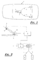
- FIG. 1 shows a motor vehicle 1, which is equipped with a functional system such as a brake secondary designated also in the state of the art earlier under the name of parking brake.
- a functional system such as a brake secondary designated also in the state of the art earlier under the name of parking brake.
- This functional system includes a control lever 2 mounted free in rotation around a transverse axis 14, carried through the vehicle floor, as shown in Figure 2, which is associated with an electric actuator 3 allowing control the energization of cables 4, 5 associated respectively to a brake caliper 6, 7 of a rear wheel of the vehicle.
- the electric actuator 3 consists of a motor electric associated with winding / unwinding means cables for actuating the secondary brake of the vehicle.
- This figure shows the control lever 2 and the electric actuator 3 for activating the system functional.
- This electric actuator 3 comprises for example a electric motor 8 associated with means winding / unwinding 9 of at least one cable operating system.
- the control lever 2 is associated with a position 10 intended to transmit to a computer 11 to which it is connected information of movement of said lever, in the direction and in amplitude along the lever travel 2 between its extreme positions.
- the computer 11 is thus able to draw information therefrom actuator supply means control for apply to it a quantity of current corresponding to the displacement of the lever from a law of correspondence predetermined.
- control lever 2 is provided with a push button type memory switch position 12 which is connected to the computer 11 so as to transmit depending on the active or inactive position of the switch information is maximum power in amount of energy from the actuator to tighten the organs braking is a leveling proportional to the position of the lever of the supply means so as to release the braking devices, i.e. by means of consequence of winding or unwinding the connected cables 4, 5 to stirrups 6 and 7.
- the vehicle in the parking position has the braking 7 and 8 applied so that the control lever 2 located in the low position, that is to say arranged substantially horizontally and the switch 12 in the actuated position 12a as shown in Figure 3 at position A.
- the user can thus manage the cable tension and its tensioning speed and thereby regulate the clamping force braking members by moving in one direction or in another the control lever 2.
- the tightening of the braking members may be proportional to the stroke of the lever 2.
- the secondary brake hand control device is particularly simple to use and offers the advantage of being able to actuate a simple tightening or brake release by simple electrical control, without this action requiring action on the lever command 2.
Abstract
Description
La présente invention concerne un dispositif de commande à main des organes de freinage secondaire d'un véhicule automobile.The present invention relates to a device for hand control of the secondary braking members of a motor vehicle.
Elle se rapporte plus particulièrement à un dispositif de commande à main permettant de piloter un actionneur électrique de manière à activer ou désactiver les organes de freinage reliés aux roues du véhicule qui sont constitués, par exemple, d'au moins deux câbles associés respectivement à un étrier de freinage d'une roue arrière ou avant du véhicule, par enroulement ou déroulement des câbles.It relates more particularly to a device for hand control for controlling an actuator electric so as to activate or deactivate the organs of braking connected to the vehicle wheels which are made, by example, at least two cables respectively associated with a brake caliper of a rear or front wheel of the vehicle, by winding or unwinding the cables.
On connaít déjà un dispositif de commande à main constitué d'un interrupteur permettant d'alimenter ou non l'actionneur, c'est-à-dire de provoquer un serrage ou un desserrage complet des organes de freinage du véhicule.We already know a hand control device consisting of a switch allowing to power or not the actuator, i.e. to cause a tightening or a complete release of the vehicle's braking devices.
Un tel dispositif de commande présente l'inconvénient de fournir une information du type tout ou rien, empêchant ainsi tout réglage de l'effort de freinage par l'utilisateur lors notamment d'un démarrage en côte du véhicule.Such a control device has the disadvantage of providing all-or-nothing information, thereby preventing any adjustment of the braking force by the user during including a hill start of the vehicle.
Afin de remédier à cet inconvénient, on connaít également notamment par la demande de brevet français n°98 07524 déposée le 15 juin 1998 par les présentes demanderesses, un dispositif de commande d'un frein secondaire électrique constitué d'un levier de frein à main traditionnel associé à un actionneur électrique lui-même relié à des moyens d'enroulement/déroulement des câbles d'actionnement du frein secondaire du véhicule qui permet de mettre sous tension les câbles de serrage du frein secondaire en fonction d'une information de position dudit levier délivrée par un capteur qui lui est associé. Un calculateur permet de piloter en fonction de l'information de position du levier les quantités de courant à envoyer à l'actionneur électrique. L'utilisateur gère ainsi la tension du câble et sa vitesse de mise en tension et régule celle-ci en fonction de la décélération du véhicule. To overcome this drawback, we also know in particular by French patent application n ° 98 07524 filed on June 15, 1998 by the present plaintiffs, a electric secondary brake control device consisting of a traditional handbrake lever associated with a electric actuator itself connected to means for winding / unwinding the brake actuation cables secondary of the vehicle which allows to energize the secondary brake clamp cables depending on a position information of said lever delivered by a sensor which associated with it. A computer allows you to control according to lever position information the amounts of current to send to the electric actuator. The user thus manages the cable tension and its tensioning speed and regulates this as a function of the deceleration of the vehicle.
Un tel dispositif de commande à main d'un frein de stationnement électrique s'avère satisfaisant pour régler les efforts de freinage lors par exemple d'un démarrage en côte ou encore en décélération dynamique. Toutefois, lorsque l'utilisateur désire le serrage ou le desserrage complet des organes de freinage une telle commande se révèle peu agréable.Such a hand brake control device electric parking is satisfactory for adjusting the braking forces for example when starting on a hill or still in dynamic deceleration. However, when the user wants to fully tighten or loosen the braking devices such an order proves little pleasant.
Le but de la présente invention est de proposer un dispositif de commande à main d'un frein de stationnement du type décrit ci-dessus qui permet de remédier à l'inconvénient susmentionné.The purpose of the present invention is to provide a hand control device for a parking brake type described above which overcomes the disadvantage mentioned above.
A cet effet, la présente invention concerne un dispositif de commande à main d'un actionneur électrique d'activation d'un système fonctionnel, notamment d'un frein secondaire de véhicule automobile, comportant un levier de commande actionnable par un utilisateur pour piloter l'alimentation de l'actionneur électrique en fonction d'une information de position dudit levier délivrée par un capteur qui lui est associé, ledit capteur étant relié à un calculateur pilotant en fonction de l'information de position du levier les quantités de courant à envoyer à l'actionneur électrique, caractérisé en ce que le levier de commande est pourvu d'un interrupteur qui est relié au calculateur de manière à transmettre en fonction de la position de l'interrupteur une information soit d'alimentation maximale en quantité d'énergie de l'actionneur afin de serrer les organes de freinage soit une remise à niveau proportionnel à la position du levier des moyens d'alimentation de façon à desserrer les organes de freinage.To this end, the present invention relates to a device for manual control of an electric actuator for activating a functional system, including a secondary brake motor vehicle, comprising a control lever can be operated by a user to control the supply of the electric actuator based on information from position of said lever delivered by a sensor attached thereto associated, said sensor being connected to a computer controlling depending on the lever position information the quantities of current to be sent to the electric actuator, characterized in that the control lever is provided with a switch which is connected to the computer so as to transmit according to the switch position information either power maximum amount of actuator energy in order to tighten the braking devices or a proportional leveling at the position of the lever of the supply means so as to loosen the braking devices.
Selon une autre caractéristique avantageuse de la présente invention, l'actionneur électrique est constitué d'un moteur électrique associé à des moyens d'enroulement/déroulement d'au moins un câble d'actionnement du système fonctionnel.According to another advantageous characteristic of the present invention, the electric actuator consists of a electric motor associated with means winding / unwinding of at least one cable operating system.
Selon encore une autre caractéristique, l'interrupteur est un bouton poussoir. According to yet another characteristic, the switch is a push button.
Selon encore une autre caractéristique, le levier de commande est monté libre en rotation autour d'un axe transversal solidaire du plancher du véhicule.According to yet another characteristic, the lever control is mounted free to rotate around an axis transverse to the vehicle floor.
Les caractéristiques de l'invention mentionnées ci-dessus, ainsi que d'autres, apparaítront plus clairement à la lecture de la description suivante d'un exemple de réalisation, en se référant aux dessins annexés sur lesquels :
- la figure 1 est un schéma synoptique illustrant l'implantation d'un dispositif de commande d'un actionneur électrique d'activation d'un système fonctionnel tel qu'un frein secondaire de véhicule automobile,
- la figure 2 est un schéma synoptique illustrant la structure et le fonctionnement d'un tel dispositif, et
- la figure 3 est un schéma illustrant les différents modes opératoires du dispositif de commande à main du frein secondaire selon l'invention.
- FIG. 1 is a block diagram illustrating the installation of a control device for an electric actuator for activating a functional system such as a secondary brake of a motor vehicle,
- FIG. 2 is a block diagram illustrating the structure and operation of such a device, and
- Figure 3 is a diagram illustrating the various operating modes of the secondary brake hand control device according to the invention.
On a représenté à la figure 1, un véhicule automobile 1,
qui est équipé d'un système fonctionnel tel qu'un frein
secondaire désigné également dans l'état de la technique
antérieure sous le nom de frein de parcage.FIG. 1 shows a
Ce système fonctionnel comporte un levier de commande
2 monté libre en rotation autour d'un axe transversal 14, porté
par le plancher du véhicule, comme visible à la figure 2, qui
est associé à un actionneur électrique 3 permettant de
contrôler la mise sous tension de câbles 4, 5 associés
respectivement à un étrier 6, 7 de freinage d'une roue arrière
du véhicule.This functional system includes a
L'actionneur électrique 3 est constitué d'un moteur électrique associé à des moyens d'enroulement/déroulement des câbles d'actionnement du frein secondaire du véhicule.The electric actuator 3 consists of a motor electric associated with winding / unwinding means cables for actuating the secondary brake of the vehicle.
On a représenté à la figure 2, un exemple de réalisation du dispositif de commande à main d'un frein secondaire. There is shown in Figure 2, an embodiment of the secondary brake hand control device.
Sur cette figure, on a représenté le levier de commande 2
et l'actionneur électrique 3 d'activation du système
fonctionnel.This figure shows the
Cet actionneur électrique 3 comporte par exemple un
moteur électrique 8 associé à des moyens
d'enroulement/déroulement 9 d'au moins un câble
d'actionnement du système fonctionnel.This electric actuator 3 comprises for example a
Le levier de commande 2 est associé à un capteur de
position 10 destiné à transmettre à un calculateur 11 auquel il
est relié une information de déplacement dudit levier, en sens
et en amplitude le long de la course de déplacement du levier
2 entre ses positions extrêmes.The
Le calculateur 11 est ainsi apte à en tirer une information
de commande de moyens d'alimentation de l'actionneur pour
appliquer à celui-ci une quantité de courant correspondant au
déplacement du levier à partir d'une loi de correspondance
prédéterminée.The
On réalise ainsi un asservissement entre la tension des
câbles et l'information de position de l'organe de commande
délivrée par le capteur 10.There is thus enslavement between the tension of the
cables and position information of the controller
delivered by the
Selon la présente invention, le levier de commande 2 est
pourvu d'un interrupteur du type bouton poussoir à mémoire de
position 12 qui est relié au calculateur 11 de manière à
transmettre en fonction de la position active ou inactive de
l'interrupteur une information soit d'alimentation maximale en
quantité d'énergie de l'actionneur afin de serrer les organes
de freinage soit une remise à niveau proportionnel à la
position du levier des moyens d'alimentation de façon à
desserrer les organes de freinage, c'est-à-dire par voie de
conséquence à enrouler ou à dérouler les câbles 4, 5 reliés
aux étriers 6 et 7.According to the present invention, the
Le fonctionnement du dispositif de commande à main du frein secondaire électrique selon la présente invention va maintenant être décrit en relation avec les figures 2 et 3. The operation of the hand control device electric secondary brake according to the present invention will now be described in relation to Figures 2 and 3.
Le véhicule en position de stationnement a les organes de
freinage 7 et 8 serrés de sorte que le levier de commande 2 se
trouve en position basse, c'est-à-dire disposé sensiblement
horizontalement et l'interrupteur 12 en position actionné 12a
comme représenté à la figure 3 à la position A.The vehicle in the parking position has the
Dès lors que l'utilisateur désire passer à la position de
roulage correspondant au desserrage complet des organes de
freinage, représenté à la position D sur la figure 3, il lui suffit
d'actionner l'interrupteur 12 en position 12b du levier de
commande ce qui envoi une information au calculateur 11
entraínant ainsi une remise à zéro des moyens d'alimentation
3, c'est-à-dire un déroulement des câbles 4, 5.When the user wishes to move to the position of
rolling corresponding to the complete loosening of the
braking, shown in position D in Figure 3, it suffices
operate the
Cette action se révèle ainsi particulièrement simple à
réaliser et ne nécessite pas un serrage préalable par le
déplacement du levier 2.This action turns out to be particularly simple to
do not require prior tightening by the
moving the
On comprend aisément qu'inversement, il est possible
pour l'utilisateur de passer de la position de roulage D à la
position de parcage A du véhicule, en actionnant l'interrupteur
12 qui transmet ainsi une information de serrage complet des
organes de freinage au calculateur 11. Le calculateur
détermine alors la quantité de courant nécessaire à envoyer
pour enrouler au maximum les câbles 4, 5 et ainsi les mettre
en tension.It is easy to understand that, conversely, it is possible
for the user to switch from driving position D to
parking position A of the vehicle, by actuating the
Lors d'une opération de démarrage en côte, positions B
et C, l'utilisateur ayant serré préalablement complètement les
organes de freinage en actionnant l'interrupteur 12, se
retrouve en position A. L'utilisateur doit alors tirer le levier de
commande 2 suivant un angle α correspondant à un serrage de
frein à main traditionnel, entraínant ainsi une information de
déplacement du levier qui est mesuré par le capteur 10 et
transmis au calculateur 11. L'utilisateur actionne alors
l'interrupteur 12 afin de desserrer les organes de freinages. Le
calculateur 11 gère alors la différence entre la course
complète d'un serrage des organes de freinage et la course
demandée par le déplacement du levier 2 afin d'envoyer une
quantité de courant suffisante pour dérouler les câbles 4, 5.During a hill start operation, positions B
and C, the user having completely tightened the
braking devices by actuating the
L'utilisateur peut ainsi gérer la tension des câbles et sa
vitesse de mise en tension et réguler ainsi l'effort de serrage
des organes de freinage en déplaçant dans un sens ou dans
un autre le levier de commande 2.The user can thus manage the cable tension and its
tensioning speed and thereby regulate the clamping force
braking members by moving in one direction or in
another the
De même, lorsque ce dernier désire effectué une
décélération dynamique au moyen des organes de freinage,
positions E à F, un simple déplacement du levier de commande
2 vers le haut permet d'envoyer une information de serrage
progressif des organes de freinage au calculateur 11 qui
transmet à l'actionneur 3 une quantité de courant
correspondant au déplacement du levier.Similarly, when the latter wishes to make a
dynamic deceleration by means of braking devices,
positions E to F, a simple movement of the
On notera que le serrage des organes de freinage peut
être proportionnel à la course du levier 2.It will be noted that the tightening of the braking members may
be proportional to the stroke of the
Une simple action sur l'interrupteur 12 permet alors de
serrer complètement les organes de freinage en transmettant
cette information au calculateur 11 et de maintenir cet état.
Ainsi, l'utilisateur est libre de basculer vers le bas levier 2.A simple action on the
On comprend à la lecture de la description ci-dessus que
le dispositif de commande à main d'un frein secondaire selon
la présente invention s'avère particulièrement simple à utiliser
et offre l'avantage de pouvoir actionner un simple serrage ou
desserrage des freins par une simple commande électrique,
sans que cette action nécessite une action sur le levier de
commande 2.It is understood from reading the description above that
the secondary brake hand control device according to
the present invention is particularly simple to use
and offers the advantage of being able to actuate a simple tightening or
brake release by simple electrical control,
without this action requiring action on the
Bien que l'invention ait été décrite en liaison avec un mode de réalisation particulier, elle comprend tous les équivalents techniques des moyens décrits.Although the invention has been described in connection with a particular embodiment, it includes all technical equivalents of the means described.
Claims (5)
Applications Claiming Priority (2)
| Application Number | Priority Date | Filing Date | Title |
|---|---|---|---|
| FR9809975 | 1998-08-04 | ||
| FR9809975A FR2782178B1 (en) | 1998-08-04 | 1998-08-04 | HAND CONTROL DEVICE OF AN ELECTRIC ACTUATOR FOR ACTIVATION OF A FUNCTIONAL SYSTEM, IN PARTICULAR OF A SECONDARY MOTOR VEHICLE BRAKE |
Publications (1)
| Publication Number | Publication Date |
|---|---|
| EP0978432A1 true EP0978432A1 (en) | 2000-02-09 |
Family
ID=9529365
Family Applications (1)
| Application Number | Title | Priority Date | Filing Date |
|---|---|---|---|
| EP99401961A Withdrawn EP0978432A1 (en) | 1998-08-04 | 1999-08-02 | Manual control device for an electronic operator actuating a system function , especially a secondary motor vehicle brake |
Country Status (2)
| Country | Link |
|---|---|
| EP (1) | EP0978432A1 (en) |
| FR (1) | FR2782178B1 (en) |
Cited By (10)
| Publication number | Priority date | Publication date | Assignee | Title |
|---|---|---|---|---|
| FR2812255A1 (en) * | 2000-07-31 | 2002-02-01 | Dura France | Parking brake control for motor vehicle has manual lever mounted in frame with transducer to send control signals to electric brake actuator |
| FR2812256A1 (en) * | 2000-07-31 | 2002-02-01 | Dura France | Electric parking brake control for motor vehicle has transducer actuated manually to produce control signal for brake actuator |
| WO2004000618A1 (en) * | 2002-06-25 | 2003-12-31 | Pbr Australia Pty Ltd | System of operation of an electric brake |
| WO2008049798A2 (en) * | 2006-10-24 | 2008-05-02 | Avl List Gmbh | Parking brake device |
| WO2011039556A1 (en) * | 2009-09-29 | 2011-04-07 | Renault Trucks | Electronically controlled park brake system |
| GB2502996A (en) * | 2012-06-13 | 2013-12-18 | Nissan Motor Mfg Uk Ltd | Handbrake having a pivotable lever and a lock mechanism releasable by an electronic actuator |
| ITTO20131046A1 (en) * | 2013-12-19 | 2015-06-20 | Fiat Group Automobiles Spa | HAND BRAKE LEVER WITH ARPIONISM ELECTRICALLY-CONTROLLED |
| US9744950B1 (en) | 2016-08-09 | 2017-08-29 | Ford Global Technologies | Performance electric parking brake controllers |
| US9975529B2 (en) | 2016-08-09 | 2018-05-22 | Ford Global Technologies, Llc | Performance electric parking brake controllers |
| US10688973B2 (en) | 2018-04-30 | 2020-06-23 | Flex-N-Gate Advanced Product Development Llc | Parking brake emulator |
Citations (4)
| Publication number | Priority date | Publication date | Assignee | Title |
|---|---|---|---|---|
| DE3210402A1 (en) * | 1982-03-22 | 1983-09-22 | SWF-Spezialfabrik für Autozubehör Gustav Rau GmbH, 7120 Bietigheim-Bissingen | Brake system, especially for motor vehicles |
| US4629043A (en) * | 1983-01-31 | 1986-12-16 | Mazda Motor Corporation | Electric parking brake system for a vehicle |
| DE3909907A1 (en) * | 1989-03-25 | 1990-09-27 | Bosch Gmbh Robert | Parking brake for motor vehicles |
| FR2691934A1 (en) * | 1992-06-06 | 1993-12-10 | Fichtel & Sachs Ag | Device for actuating a parking brake on a motor vehicle. |
-
1998
- 1998-08-04 FR FR9809975A patent/FR2782178B1/en not_active Expired - Fee Related
-
1999
- 1999-08-02 EP EP99401961A patent/EP0978432A1/en not_active Withdrawn
Patent Citations (4)
| Publication number | Priority date | Publication date | Assignee | Title |
|---|---|---|---|---|
| DE3210402A1 (en) * | 1982-03-22 | 1983-09-22 | SWF-Spezialfabrik für Autozubehör Gustav Rau GmbH, 7120 Bietigheim-Bissingen | Brake system, especially for motor vehicles |
| US4629043A (en) * | 1983-01-31 | 1986-12-16 | Mazda Motor Corporation | Electric parking brake system for a vehicle |
| DE3909907A1 (en) * | 1989-03-25 | 1990-09-27 | Bosch Gmbh Robert | Parking brake for motor vehicles |
| FR2691934A1 (en) * | 1992-06-06 | 1993-12-10 | Fichtel & Sachs Ag | Device for actuating a parking brake on a motor vehicle. |
Cited By (17)
| Publication number | Priority date | Publication date | Assignee | Title |
|---|---|---|---|---|
| FR2812255A1 (en) * | 2000-07-31 | 2002-02-01 | Dura France | Parking brake control for motor vehicle has manual lever mounted in frame with transducer to send control signals to electric brake actuator |
| FR2812256A1 (en) * | 2000-07-31 | 2002-02-01 | Dura France | Electric parking brake control for motor vehicle has transducer actuated manually to produce control signal for brake actuator |
| EP1179462A1 (en) * | 2000-07-31 | 2002-02-13 | Dura France | Control device of a motor vehicle electric parking brake |
| EP1179463A1 (en) * | 2000-07-31 | 2002-02-13 | Dura France | Control device of an electric parking brake comprising a transducer |
| WO2004000618A1 (en) * | 2002-06-25 | 2003-12-31 | Pbr Australia Pty Ltd | System of operation of an electric brake |
| CN101557969B (en) * | 2006-10-24 | 2012-05-30 | Avl里斯脱有限公司 | Parking brake device |
| WO2008049798A3 (en) * | 2006-10-24 | 2008-10-02 | Avl List Gmbh | Parking brake device |
| WO2008049798A2 (en) * | 2006-10-24 | 2008-05-02 | Avl List Gmbh | Parking brake device |
| WO2011039556A1 (en) * | 2009-09-29 | 2011-04-07 | Renault Trucks | Electronically controlled park brake system |
| EP2483113B1 (en) | 2009-09-29 | 2015-08-12 | Volvo Lastvagnar AB | Electronically controlled park brake system |
| GB2502996A (en) * | 2012-06-13 | 2013-12-18 | Nissan Motor Mfg Uk Ltd | Handbrake having a pivotable lever and a lock mechanism releasable by an electronic actuator |
| EP2674335A3 (en) * | 2012-06-13 | 2017-08-02 | Nissan Motor Manufacturing (UK) Ltd. | Handbrake |
| ITTO20131046A1 (en) * | 2013-12-19 | 2015-06-20 | Fiat Group Automobiles Spa | HAND BRAKE LEVER WITH ARPIONISM ELECTRICALLY-CONTROLLED |
| EP2886405A1 (en) * | 2013-12-19 | 2015-06-24 | Fiat Group Automobiles S.p.A. | Hand brake lever with electrically-operated ratchet mechanism |
| US9744950B1 (en) | 2016-08-09 | 2017-08-29 | Ford Global Technologies | Performance electric parking brake controllers |
| US9975529B2 (en) | 2016-08-09 | 2018-05-22 | Ford Global Technologies, Llc | Performance electric parking brake controllers |
| US10688973B2 (en) | 2018-04-30 | 2020-06-23 | Flex-N-Gate Advanced Product Development Llc | Parking brake emulator |
Also Published As
| Publication number | Publication date |
|---|---|
| FR2782178B1 (en) | 2000-09-08 |
| FR2782178A1 (en) | 2000-02-11 |
Similar Documents
| Publication | Publication Date | Title |
|---|---|---|
| EP1003656B1 (en) | Method and device for controlling an electric actuator activating a functional system | |
| JP2931402B2 (en) | Operating device for car parking brake | |
| FR2691934A1 (en) | Device for actuating a parking brake on a motor vehicle. | |
| EP0978432A1 (en) | Manual control device for an electronic operator actuating a system function , especially a secondary motor vehicle brake | |
| EP1655190B1 (en) | Vehicle parking brake actuator with electric force feedback | |
| FR2610590A1 (en) | DEVICE FOR SLOWING A BICYCLE | |
| FR2597418A1 (en) | DEVICE FOR REGULATING THE DRIVE POWER OF A MOTOR VEHICLE | |
| EP0706922B1 (en) | Control of a parking brake and a gearbox | |
| FR2614362A1 (en) | DEVICE FOR ADJUSTING A GAS BUTTERFLY FOR CONTROLLING TRACTION SLIDING OR SPEED | |
| EP0919903B1 (en) | Assisting device for actuating a lever | |
| FR2523536A1 (en) | MOTOR VEHICLE COMPRISING AT LEAST ONE BRAKE SYSTEM AND A MOTOR, AND MEANS FOR CONTROLLING THE BRAKING SYSTEM AT THE STOPPING OF THE ENGINE | |
| EP0554133A1 (en) | Mechanical assistance device with spring | |
| EP0978431B1 (en) | Hand operated electric switch device for operation of a secondary brake of a vehicle | |
| EP0546927B1 (en) | Hand brake lever for a parking brake | |
| FR2761654A1 (en) | Flexible link control with play pickup for vehicle handbrake | |
| FR2771360A1 (en) | PARKING BRAKE INSTALLATION FOR MOTOR VEHICLES | |
| EP0680863B1 (en) | Brake system with dual control and condition monitoring | |
| FR2871424A1 (en) | Parking brake for e.g. car, has force transmission cable wounded on pulley coupled with pinion of reducer that is coupled with auger for transmitting force to auger, where reducer reduces force transmitted by cable | |
| EP1534567B1 (en) | Acceleration and braking control device for vehicle | |
| FR2728836A1 (en) | Control system for electrically driven vehicle | |
| EP1972517B1 (en) | Method and system for controlling an automatic parking brake | |
| FR2874564A1 (en) | Braking device for electric driven quad type motor vehicle, has brake pressure regulating valve comprising braking assistance and force reproduction unit with braking assistance function and force reproduction function | |
| FR3126113A1 (en) | ENHANCED CONTROL PARKING BRAKE SYSTEM | |
| EP1115597A1 (en) | Power-driven parking brake comprising possible manual actuation | |
| KR100224421B1 (en) | A parking brake having an anti-lock system |
Legal Events
| Date | Code | Title | Description |
|---|---|---|---|
| PUAI | Public reference made under article 153(3) epc to a published international application that has entered the european phase |
Free format text: ORIGINAL CODE: 0009012 |
|
| AK | Designated contracting states |
Kind code of ref document: A1 Designated state(s): DE ES FR GB IT |
|
| AX | Request for extension of the european patent |
Free format text: AL;LT;LV;MK;RO;SI |
|
| 17P | Request for examination filed |
Effective date: 20000622 |
|
| AKX | Designation fees paid |
Free format text: DE ES FR GB IT |
|
| 17Q | First examination report despatched |
Effective date: 20050422 |
|
| GRAP | Despatch of communication of intention to grant a patent |
Free format text: ORIGINAL CODE: EPIDOSNIGR1 |
|
| RTI1 | Title (correction) |
Free format text: MANUAL CONTROL DEVICE FOR AN ELECTRIC OPERATOR OF A BRAKING SYSTEM, ESPECIALLY A SECONDARY MOTOR VEHICLE BRAKE |
|
| STAA | Information on the status of an ep patent application or granted ep patent |
Free format text: STATUS: THE APPLICATION IS DEEMED TO BE WITHDRAWN |
|
| 18D | Application deemed to be withdrawn |
Effective date: 20060531 |