EP0978409A2 - Kombinationsinstrument - Google Patents
Kombinationsinstrument Download PDFInfo
- Publication number
- EP0978409A2 EP0978409A2 EP99114305A EP99114305A EP0978409A2 EP 0978409 A2 EP0978409 A2 EP 0978409A2 EP 99114305 A EP99114305 A EP 99114305A EP 99114305 A EP99114305 A EP 99114305A EP 0978409 A2 EP0978409 A2 EP 0978409A2
- Authority
- EP
- European Patent Office
- Prior art keywords
- hollow body
- combination instrument
- display instruments
- instrument according
- instrument
- Prior art date
- Legal status (The legal status is an assumption and is not a legal conclusion. Google has not performed a legal analysis and makes no representation as to the accuracy of the status listed.)
- Granted
Links
Images



Classifications
-
- B—PERFORMING OPERATIONS; TRANSPORTING
- B60—VEHICLES IN GENERAL
- B60K—ARRANGEMENT OR MOUNTING OF PROPULSION UNITS OR OF TRANSMISSIONS IN VEHICLES; ARRANGEMENT OR MOUNTING OF PLURAL DIVERSE PRIME-MOVERS IN VEHICLES; AUXILIARY DRIVES FOR VEHICLES; INSTRUMENTATION OR DASHBOARDS FOR VEHICLES; ARRANGEMENTS IN CONNECTION WITH COOLING, AIR INTAKE, GAS EXHAUST OR FUEL SUPPLY OF PROPULSION UNITS IN VEHICLES
- B60K35/00—Instruments specially adapted for vehicles; Arrangement of instruments in or on vehicles
- B60K35/60—Instruments characterised by their location or relative disposition in or on vehicles
-
- B—PERFORMING OPERATIONS; TRANSPORTING
- B60—VEHICLES IN GENERAL
- B60K—ARRANGEMENT OR MOUNTING OF PROPULSION UNITS OR OF TRANSMISSIONS IN VEHICLES; ARRANGEMENT OR MOUNTING OF PLURAL DIVERSE PRIME-MOVERS IN VEHICLES; AUXILIARY DRIVES FOR VEHICLES; INSTRUMENTATION OR DASHBOARDS FOR VEHICLES; ARRANGEMENTS IN CONNECTION WITH COOLING, AIR INTAKE, GAS EXHAUST OR FUEL SUPPLY OF PROPULSION UNITS IN VEHICLES
- B60K35/00—Instruments specially adapted for vehicles; Arrangement of instruments in or on vehicles
- B60K35/50—Instruments characterised by their means of attachment to or integration in the vehicle
-
- B—PERFORMING OPERATIONS; TRANSPORTING
- B60—VEHICLES IN GENERAL
- B60K—ARRANGEMENT OR MOUNTING OF PROPULSION UNITS OR OF TRANSMISSIONS IN VEHICLES; ARRANGEMENT OR MOUNTING OF PLURAL DIVERSE PRIME-MOVERS IN VEHICLES; AUXILIARY DRIVES FOR VEHICLES; INSTRUMENTATION OR DASHBOARDS FOR VEHICLES; ARRANGEMENTS IN CONNECTION WITH COOLING, AIR INTAKE, GAS EXHAUST OR FUEL SUPPLY OF PROPULSION UNITS IN VEHICLES
- B60K35/00—Instruments specially adapted for vehicles; Arrangement of instruments in or on vehicles
- B60K35/65—Instruments specially adapted for specific vehicle types or users, e.g. for left- or right-hand drive
- B60K35/654—Instruments specially adapted for specific vehicle types or users, e.g. for left- or right-hand drive the user being the driver
Definitions
- the invention relates to a combination instrument, in particular for a watercraft, with an instrument holder to accommodate several display instruments.
- Combination instruments of the type mentioned are used today often with different land and water vehicles, for example also for yachts, but also for stationary machines, e.g. Generators, used.
- a mostly box-shaped instrument holder includes several display instruments that are used for Protection against penetrating moisture and dust particles are sealed.
- the instrument holder is common by means of a bracket at a suitable point on the Cockpits are pivoted so that the reading angle individually adjustable to the needs of the user is.
- the display instruments can be viewed from the front as well also inserted from behind into the instrument holder his. This is also suitable for retrofitting others Display instruments.
- the combination instrument described has a disadvantageous effect from that in corresponding recesses display instruments used carefully against the Instrument carriers must be sealed, otherwise slightly moisture in the combination instrument penetrate and cause damage to the display instruments can.
- the invention is based on the problem of a combination instrument of the type mentioned so that the Instrument carrier particularly good against penetrating environmental influences is protected. At the same time the display instruments easily in the instrument holder be mountable.
- the instrument carrier at least in sections has transparent hollow body, which inside the display instruments in such a way that the Viewing the display instruments through the hollow body for a viewer is visible.
- the display instruments in With the exception of a mounting opening on all sides closed hollow body can be arranged without this requires a special seal.
- the Gauges are transparent due to the arrangement in the Hollow body can be read easily; is the hollow body only transparent in sections, so they are Display the gauges through these sections visible and readable.
- the display instruments can, for example, by a rear opening of the hollow body in the interior be introduced.
- the Hollow body is tubular and the ends of the hollow body are each closed by means of a side part. This allows the display instruments to go through effortlessly the initially unsealed ends of the hollow body inserted and fixed inside the hollow body. Then only need the side parts to be put on. It is also conceivable that the hollow body with one of the side parts a single one Component is connected to form. Such a pot-shaped Hollow body is loaded from its open side and closed with the second side part.
- the one in the area of the back of the display instruments Section of the hollow body can be a cover or coating to keep an eye on the components to block the display instruments.
- Very cheap is, however, an embodiment of the invention in which the hollow body a transparent, the front of the Section inclined towards the display instruments and an opaque, inclined towards the back of the display instruments Section. This will make it a simple and at the same time effective privacy protection against the rear Components reached.
- the radiation is also added of extraneous light in the back of the display instruments prevents the reading accuracy especially in the dark and backlit display instruments is improved. At the same time it becomes a Shielding the surroundings of the combination instrument light radiation emerging diffusely from the hollow body of the display instruments, often referred to as is perceived as disturbing.
- the hollow body could, for example, consist of a transparent and an opaque half-shell be composed.
- the hollow body in the two-component injection molding process is produced and a first, transparent area and a second, opaque area having. This allows one-piece Hollow body both an essentially transparent area as well as an essentially opaque Reach area. The assembly effort is relative low.
- the hollow body can have a receptacle on its inside for the display instruments.
- the Side parts a fixative for the display instruments exhibit. This allows the display instruments to be used fix it with little effort inside the hollow body.
- the display instruments can, for example first connected to the side part and then be introduced as a unit in the hollow body. Therefore the effort of known combination instruments is eliminated through assembly work inside the Instrument carrier arises.
- the fixation takes place of the display instruments due to the arrangement of the Fixing agent on the side parts regardless of that Hollow body, which procures as a standard component and can be cut to length.
- the fixing agent for inserting a common circuit board of the display instruments is executed.
- a connector allows the fixation of the board in the example as Grooved bracket without additional fasteners and special tools.
- the display instruments can with their common board with a Handle can be removed from the holder, for example at the same time with the necessary electrical Contacts can be provided. This allows replace the display instruments as a unit or outside of the hollow body with the desired additional Retrofit display instruments that are optimal and customized with a professional visual appearance can be.
- the side parts can for example by means of a Screw connection to be connected to the hollow body.
- a further development of the Invention in which the hollow body between the against each other tensioned side panels is fixed.
- the two opposite side parts for example connected to each other by means of a screw connection.
- the side parts can additionally have a guide, for example have a groove that slips the Prevents hollow body transverse to the direction of fixation.
- One embodiment of the invention is then special advantageous if at least one side part has a recess for electrical contacting.
- the hollow body can be made free of openings, which further improves protection of the hollow body against environmental influences.
- the electrical Contacting can also be done in a Support bracket integrated and therefore not visible from the outside be arranged.
- Switching elements or plug contacts can also be used be arranged in the side parts.
- the Swiveling of the hollow body remains unrestricted receive.
- the hollow body can be easily replaced.
- One embodiment of the invention is then special advantageous if the hollow body in a dashboard pivotable from an operating position at which the display instruments are visible to a viewer, in a Rest position, in which the gauges through the dashboard are hidden, is arranged.
- the instrument cluster can be put into a rest position after use be pivoted so that it is free from damage and environmental influences protected in the dashboard lies.
- the instrument holder can be rotated laterally be stored.
- the dashboard can do this the extent enclose the instrument holder by more than half, so that it can be easily rotated becomes.
- the contacts can also be made for a viewer installed invisibly inside the dashboard become. It is also possible on the instrument holder to install a locking mechanism, thereby preventing an unauthorized person Prevents swiveling and thus a good one Theft protection is achieved.
- Another particularly practical embodiment of the invention is relative to the hollow body movable cover to protect against external light and damage reached.
- the cover covers you adjustable portion of the hollow body, in particular of the transparent area covering the display instruments and thus enables a simple and effective Protection, for example against solar radiation.
- the cover can do this by one on the combination instrument arranged axis can be pivoted.
- the cover is in a slide of the respective side part is.
- This can be both space-saving and effective Execution of the cover can be achieved.
- the cover is similar to a roller shutter in the for example, a groove for guiding the side part emotional.
- the side parts can also do this have a cross-sectional area that deviates from the hollow body, so the cover in a distance from that Hollow body arranged guide can be slidable.
- the relative position of the cover also changes to the hollow body by a possible pivoting movement not, so that simple operation is made possible.
- Figure 1 shows a front view of an inventive Combination instrument 1.
- the combination instrument 1 has a transparent, tubular hollow body 2, the Ends each closed by a side part 3, 4 are. Due to the essentially transparent design Hollow bodies 2 are several on a common inside Circuit board 5 attached display instruments 6, 7, 8, 9 arranged visible from the outside.
- the side parts 3, 4 are by means of a bracket 10 with only one example illustrated section of a dashboard 11 so connected that the hollow body 2 about its longitudinal axis is pivotally arranged.
- Figure 2 shows a side view of the combination instrument 1.
- the side part 3 is shown, which means of the bracket 10 connected to the dashboard 11 is.
- the combination instrument 1 is one Swivel axis 12 rotatably mounted so that an individual, comfortable reading angle adjustable for the viewer is.
- the side part 3 is by means of a screw 13 with the opposite one shown in FIG Screwed side part 4.
- the side part 3 still has a switching element 14, which for example for actuation a reset mechanism for a kilometer or Operating hours counter can be used.
- Farther is the side part 3 with one outside the field of vision of a viewer arranged electrical contact 15 provided.
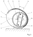
- FIG. 3 shows a sectional side view of the Combination instrument 1.
- the essentially circular Hollow body 2 takes the display instrument in its interior 9 on, the pointer flag 16 by means of a the rear of the common board 5 arranged pointer drive 17 is deflectable.
- rear area of the hollow body 2 is another, the control elements of the pointer instrument supporting board 18 arranged.
- the boards 5, 18 are each in a not shown Guide held in the side parts 3, 4.
- the boards 5, 18 are first with the side part 4 connected.
- the hollow body 2 over the Circuit boards 5, 18 and finally the second, not shown side part by means of the screw 13 and a further screw 19 against the first one in FIG. 1 shown side part 3 clamped.
- a cover which is displaceable in the region of the guide 20 21 used. This cover 21 serves to protect the Combination instrument 1 against environmental influences, for example sun exposure, and before mechanical Damage.
- Figure 4 shows a recessed in a dashboard 22 Combination instrument 23.
- Combination instrument 1 is the hollow body 2 here directly in a recess 24 of the dashboard 22 rotatably inserted, so that a support bracket is omitted.
- the hollow body 2 can be in any Angle are rotated so that by means of the pointer drive 17 deflectable pointer flag 16 optimally readable is.
- the hollow body 2 can also be compared to the shown operating position by 180 ° in a rear Rest position can be pivoted, making the combination instrument 1 is particularly well protected and for example commissioning also to protect against theft of the vehicle prevented.
- the Hollow body 2 in particular in the two-component injection molding process made and only on the front be made transparent.
- Figure 5 shows a hollow body shown in section 25 of a further combination instrument 26 in one Side view.
- the hollow body 25 a modified cross-sectional shape with one each fixing means 27, 28 arranged on its inside to accommodate a common board 5 and the rear Circuit board 18.
- the essentially transparent hollow body 25 is in the rear area by means of a opaque privacy film 29 against one Viewer shielded.
- Other embodiments can also equipped without such a privacy film 29 be to contemplate the inside, electronic Allow components.
- the display instruments 8, 9 facing section of the hollow body 25 can any suitable configuration, for example convex or concave.
- the surface of the Hollow body 25 can in addition to transparent sections also opaque coatings or areas with colored or diffuse translucent areas to have.
Landscapes
- Engineering & Computer Science (AREA)
- Chemical & Material Sciences (AREA)
- Combustion & Propulsion (AREA)
- Transportation (AREA)
- Mechanical Engineering (AREA)
- Instrument Panels (AREA)
- Details Of Measuring And Other Instruments (AREA)
Abstract
Description
- Fig. 1
- ein erfindungsgemäßes Kombinationsinstrument in einer Vorderansicht,
- Fig. 2
- das Kombinationsinstrument in einer Seitenansicht,
- Fig. 3
- das Kombinationsinstrument in einer geschnittenen Seitenansicht,
- Fig. 4
- ein in eine Armaturentafel eingebautes Kombinationsinstrument,
- Fig. 5
- ein weiteres Kombinationsinstrument mit abgenommenem Seitenteil in einer Seitenansicht.
Claims (13)
- Kombinationsinstrument, insbesondere für ein Wasserfahrzeug, mit einem Instrumententräger zur Aufnahme mehrerer Anzeigeinstrumente, dadurch gekennzeichnet, dass der Instrumententräger einen zumindest abschnittsweise transparenten Hohlkörper (2, 25) hat, welcher in seinem Inneren die Anzeigeinstrumente (6, 7, 8, 9) in der Weise aufnimmt, dass die Anzeigen der Anzeigeinstrumente (6, 7, 8, 9) durch den Hohlkörper (2, 25) für einen Betrachter sichtbar sind.
- Kombinationsinstrument nach Anspruch 1, dadurch gekennzeichnet, dass der Hohlkörper rohrförmig ist und dass die Enden des Hohlkörpers (2) jeweils mittels eines Seitenteiles (3, 4) verschlossen sind.
- Kombinationsinstrument nach Anspruch 1 oder 2, dadurch gekennzeichnet, dass der Hohlkörper (2, 25) einen transparenten, der Vorderseite der Anzeigeinstrumente (6, 7, 8, 9) zugeneigten Abschnitt und einen undurchsichtigen, der Rückseite der Anzeigeinstrumente (6, 7, 8, 9) zugeneigten Abschnitt hat.
- Kombinationsinstrument nach einem der vorhergehenden Ansprüche, dadurch gekennzeichnet, dass der Hohlkörper (2, 25) im Zweikomponenten-Spritzgießverfahren hergestellt ist und einen ersten, transparenten Bereich und einen zweiten, lichtundurchlässigen Bereich aufweist.
- Kombinationsinstrument nach einem der vorhergehenden Ansprüche, dadurch gekennzeichnet, dass die Seitenteile (3, 4) ein Fixiermittel für die Anzeigeinstrumente (6, 7, 8, 9) aufweisen.
- Kombinationsinstrument nach Anspruch 5, dadurch gekennzeichnet, dass das Fixiermittel zum Einstecken einer gemeinsamen Platine (5, 18) der Anzeigeinstrumente (6, 7, 8, 9) ausgeführt ist.
- Kombinationsinstrument nach einem der vorhergehenden Ansprüche, dadurch gekennzeichnet, dass der Hohlkörper (2, 25) zwischen den gegeneinander verspannten Seitenteilen (3, 4) fixiert ist.
- Kombinationsinstrument nach Anspruch 7, dadurch gekennzeichnet, dass die Anzeigeinstrumente (6, 7, 8, 9) in dem Hohlkörper (2, 25) gegenüber den Seitenteilen (3, 4) mit Spiel fixiert sind.
- Kombinationsinstrument nach Anspruch 7 oder 8, dadurch gekennzeichnet, dass die Seitenteile (3, 4) gegenüber dem Hohlkörper (2, 25) mittels einer Dichtung abgedichtet sind.
- Kombinationsinstrument nach einem der vorhergehenden Ansprüche, dadurch gekennzeichnet, dass zumindest ein Seitenteil (3, 4) eine Ausnehmung für eine elektrische Kontaktierung (15) hat.
- Kombinationsinstrument nach einem der vorhergehenden Ansprüche, dadurch gekennzeichnet, dass der Hohlkörper (2, 25) in einer Armaturentafel (11, 22) schwenkbar von einer Betriebsposition, bei der die Anzeigeinstrumente (6, 7, 8, 9) für einen Betrachter sichtbar sind, in eine Ruheposition, in der die Anzeigeinstrumente (6, 7, 8, 9) durch die Armaturentafel (11, 22) verdeckt sind, angeordnet ist.
- Kombinationsinstrument nach einem der vorhergehenden Ansprüche, gekennzeichnet durch eine gegenüber dem Hohlkörper (2) relativ bewegliche Abdeckung (21) zum Schutz gegen Fremdlichteinfall und Beschädigung.
- Kombinationsinstrument nach Anspruch 12, dadurch gekennzeichnet, dass die Abdeckung (21) in einer Führung (20) des jeweiligen Seitenteiles (3, 4) verschiebbar ist.
Applications Claiming Priority (2)
| Application Number | Priority Date | Filing Date | Title |
|---|---|---|---|
| DE19835215A DE19835215C2 (de) | 1998-08-05 | 1998-08-05 | Kombinationsinstrument |
| DE19835215 | 1998-08-05 |
Publications (3)
| Publication Number | Publication Date |
|---|---|
| EP0978409A2 true EP0978409A2 (de) | 2000-02-09 |
| EP0978409A3 EP0978409A3 (de) | 2001-01-31 |
| EP0978409B1 EP0978409B1 (de) | 2003-03-05 |
Family
ID=7876438
Family Applications (1)
| Application Number | Title | Priority Date | Filing Date |
|---|---|---|---|
| EP99114305A Expired - Lifetime EP0978409B1 (de) | 1998-08-05 | 1999-07-21 | Kombinationsinstrument |
Country Status (3)
| Country | Link |
|---|---|
| US (2) | US6352003B1 (de) |
| EP (1) | EP0978409B1 (de) |
| DE (2) | DE19835215C2 (de) |
Cited By (1)
| Publication number | Priority date | Publication date | Assignee | Title |
|---|---|---|---|---|
| WO2004050410A1 (de) * | 2002-12-02 | 2004-06-17 | Siemens Aktiengesellschaft | Anzeigeinstrument sowie verfahren zur herstellung eines anzeigeinstrumentes |
Families Citing this family (9)
| Publication number | Priority date | Publication date | Assignee | Title |
|---|---|---|---|---|
| DE10029729A1 (de) * | 2000-06-16 | 2002-02-21 | Mannesmann Vdo Ag | Kombiinstrument zur Anzeige von Messwerten und/oder sonstigen Hinweisen, insbesondere zur Verwendung in einem Kraftfahrzeug |
| US6854328B2 (en) * | 2001-06-14 | 2005-02-15 | Custom Spec Engineering, Inc. | Cover structure for marine instrument |
| USD555164S1 (en) * | 2004-02-11 | 2007-11-13 | Progetica S.R.L. | Interface screen |
| WO2007053399A2 (en) * | 2005-10-31 | 2007-05-10 | Auto Meter Products, Inc. | Vehicle gauge mounting bracket |
| USD542301S1 (en) * | 2006-08-17 | 2007-05-08 | Microsoft Corporation | Icon for a portion of a display screen |
| DE102007041764B4 (de) | 2007-02-21 | 2011-07-21 | Johnson Controls Automotive Electronics GmbH, 75196 | Bewegbar gelagerte Anzeige in einem Kraftfahrzeug |
| USD681649S1 (en) * | 2012-01-05 | 2013-05-07 | Flextronics Ap, Llc | Display panel with graphical user interface for analyzing and presenting supply, fabrication, and logistics data |
| USD681662S1 (en) * | 2012-01-05 | 2013-05-07 | Flextronics Ap, Llc | Display panel with graphical user interface for analyzing and presenting supply, fabrication, and logistics data |
| USD786304S1 (en) * | 2014-11-20 | 2017-05-09 | General Electric Company | Computer display or portion thereof with icon |
Family Cites Families (103)
| Publication number | Priority date | Publication date | Assignee | Title |
|---|---|---|---|---|
| DE2720764C2 (de) * | 1977-05-09 | 1983-09-22 | Vdo Adolf Schindling Ag, 6000 Frankfurt | Konsole zur Aufnahme nautischer Anzeigeinstrumente |
| US4222076A (en) * | 1978-09-15 | 1980-09-09 | Bell Telephone Laboratories, Incorporated | Progressive image transmission |
| DE2937206A1 (de) * | 1979-09-14 | 1981-04-02 | Vdo Adolf Schindling Ag, 6000 Frankfurt | Messinstrumentengehaeuse |
| FR2497996A1 (fr) * | 1981-01-15 | 1982-07-16 | Christian Estarellas | Systeme electronique autonome et insubmersible de securite nautique |
| US4475104A (en) * | 1983-01-17 | 1984-10-02 | Lexidata Corporation | Three-dimensional display system |
| US4748511A (en) * | 1984-06-07 | 1988-05-31 | Raytel Systems Corporation | Teleradiology system |
| US4910609A (en) * | 1984-06-07 | 1990-03-20 | Raytel Systems Corporation | Teleradiology system |
| US4625289A (en) * | 1985-01-09 | 1986-11-25 | Evans & Sutherland Computer Corp. | Computer graphics system of general surface rendering by exhaustive sampling |
| US4737921A (en) * | 1985-06-03 | 1988-04-12 | Dynamic Digital Displays, Inc. | Three dimensional medical image display system |
| US5005126A (en) * | 1987-04-09 | 1991-04-02 | Prevail, Inc. | System and method for remote presentation of diagnostic image information |
| US4961425A (en) * | 1987-08-14 | 1990-10-09 | Massachusetts Institute Of Technology | Morphometric analysis of anatomical tomographic data |
| US5038302A (en) * | 1988-07-26 | 1991-08-06 | The Research Foundation Of State University Of New York | Method of converting continuous three-dimensional geometrical representations into discrete three-dimensional voxel-based representations within a three-dimensional voxel-based system |
| US4987554A (en) * | 1988-08-24 | 1991-01-22 | The Research Foundation Of State University Of New York | Method of converting continuous three-dimensional geometrical representations of polygonal objects into discrete three-dimensional voxel-based representations thereof within a three-dimensional voxel-based system |
| US4985856A (en) * | 1988-11-10 | 1991-01-15 | The Research Foundation Of State University Of New York | Method and apparatus for storing, accessing, and processing voxel-based data |
| US5027110A (en) * | 1988-12-05 | 1991-06-25 | At&T Bell Laboratories | Arrangement for simultaneously displaying on one or more display terminals a series of images |
| US5205289A (en) * | 1988-12-23 | 1993-04-27 | Medical Instrumentation And Diagnostics Corporation | Three-dimensional computer graphics simulation and computerized numerical optimization for dose delivery and treatment planning |
| US5101475A (en) * | 1989-04-17 | 1992-03-31 | The Research Foundation Of State University Of New York | Method and apparatus for generating arbitrary projections of three-dimensional voxel-based data |
| FR2648090B1 (fr) * | 1989-06-13 | 1994-11-18 | Sagem | Tableau de bord de vehicule automobile |
| US4948074A (en) * | 1989-08-28 | 1990-08-14 | Crompton Modutec, Inc. | Flush mounted gauge for instrument panels of different thicknesses |
| CA2051939A1 (en) * | 1990-10-02 | 1992-04-03 | Gary A. Ransford | Digital data registration and differencing compression system |
| EP0487110B1 (de) * | 1990-11-22 | 1999-10-06 | Kabushiki Kaisha Toshiba | Rechnergestütztes System zur Diagnose für medizinischen Gebrauch |
| US5730146A (en) * | 1991-08-01 | 1998-03-24 | Itil; Turan M. | Transmitting, analyzing and reporting EEG data |
| US5291401A (en) * | 1991-11-15 | 1994-03-01 | Telescan, Limited | Teleradiology system |
| US5448686A (en) * | 1992-01-02 | 1995-09-05 | International Business Machines Corporation | Multi-resolution graphic representation employing at least one simplified model for interactive visualization applications |
| US5442733A (en) * | 1992-03-20 | 1995-08-15 | The Research Foundation Of State University Of New York | Method and apparatus for generating realistic images using a discrete representation |
| US5441047A (en) * | 1992-03-25 | 1995-08-15 | David; Daniel | Ambulatory patient health monitoring techniques utilizing interactive visual communication |
| US5360971A (en) * | 1992-03-31 | 1994-11-01 | The Research Foundation State University Of New York | Apparatus and method for eye tracking interface |
| US5384862A (en) * | 1992-05-29 | 1995-01-24 | Cimpiter Corporation | Radiographic image evaluation apparatus and method |
| US5321520A (en) * | 1992-07-20 | 1994-06-14 | Automated Medical Access Corporation | Automated high definition/resolution image storage, retrieval and transmission system |
| US6283761B1 (en) * | 1992-09-08 | 2001-09-04 | Raymond Anthony Joao | Apparatus and method for processing and/or for providing healthcare information and/or healthcare-related information |
| DE4315027A1 (de) * | 1992-12-02 | 1994-06-09 | Vdo Schindling | Kombinations-Instrument |
| US5517021A (en) * | 1993-01-19 | 1996-05-14 | The Research Foundation State University Of New York | Apparatus and method for eye tracking interface |
| IL104636A (en) * | 1993-02-07 | 1997-06-10 | Oli V R Corp Ltd | Apparatus and method for encoding and decoding digital signals |
| DE4318011A1 (de) * | 1993-05-29 | 1994-12-01 | Vdo Schindling | Anzeigeeinrichtung |
| US5544283A (en) * | 1993-07-26 | 1996-08-06 | The Research Foundation Of State University Of New York | Method and apparatus for real-time volume rendering from an arbitrary viewing direction |
| US5432871A (en) * | 1993-08-04 | 1995-07-11 | Universal Systems & Technology, Inc. | Systems and methods for interactive image data acquisition and compression |
| JP2605598B2 (ja) * | 1993-08-20 | 1997-04-30 | 日本電気株式会社 | 指紋画像の伝送装置 |
| US5377258A (en) * | 1993-08-30 | 1994-12-27 | National Medical Research Council | Method and apparatus for an automated and interactive behavioral guidance system |
| DE4332716A1 (de) * | 1993-09-25 | 1995-03-30 | Vdo Schindling | Kombinations-Instrument |
| US5408249A (en) * | 1993-11-24 | 1995-04-18 | Radiation Measurements, Inc. | Bit extension adapter for computer graphics |
| US5469353A (en) * | 1993-11-26 | 1995-11-21 | Access Radiology Corp. | Radiological image interpretation apparatus and method |
| US5660176A (en) * | 1993-12-29 | 1997-08-26 | First Opinion Corporation | Computerized medical diagnostic and treatment advice system |
| US5482043A (en) * | 1994-05-11 | 1996-01-09 | Zulauf; David R. P. | Method and apparatus for telefluoroscopy |
| EP0780010A4 (de) * | 1994-09-06 | 1997-11-12 | Univ New York State Res Found | Apparat und verfahren für die echtzeitvisualisierung von rauminhalten |
| US5594842A (en) * | 1994-09-06 | 1997-01-14 | The Research Foundation Of State University Of New York | Apparatus and method for real-time volume visualization |
| US5838906A (en) * | 1994-10-17 | 1998-11-17 | The Regents Of The University Of California | Distributed hypermedia method for automatically invoking external application providing interaction and display of embedded objects within a hypermedia document |
| US5883976A (en) * | 1994-12-28 | 1999-03-16 | Canon Kabushiki Kaisha | Selectively utilizing multiple encoding methods |
| US5594935A (en) * | 1995-02-23 | 1997-01-14 | Motorola, Inc. | Interactive image display system of wide angle images comprising an accounting system |
| US5649173A (en) * | 1995-03-06 | 1997-07-15 | Seiko Epson Corporation | Hardware architecture for image generation and manipulation |
| US5882206A (en) * | 1995-03-29 | 1999-03-16 | Gillio; Robert G. | Virtual surgery system |
| US6807558B1 (en) * | 1995-06-12 | 2004-10-19 | Pointcast, Inc. | Utilization of information “push” technology |
| DE19537233A1 (de) * | 1995-10-06 | 1997-04-10 | Bayerische Motoren Werke Ag | Instrumententräger für ein Kraftfahrzeug |
| US5797515A (en) * | 1995-10-18 | 1998-08-25 | Adds, Inc. | Method for controlling a drug dispensing system |
| US5805118A (en) * | 1995-12-22 | 1998-09-08 | Research Foundation Of The State Of New York | Display protocol specification with session configuration and multiple monitors |
| US5603323A (en) * | 1996-02-27 | 1997-02-18 | Advanced Technology Laboratories, Inc. | Medical ultrasonic diagnostic system with upgradeable transducer probes and other features |
| US5715823A (en) * | 1996-02-27 | 1998-02-10 | Atlantis Diagnostics International, L.L.C. | Ultrasonic diagnostic imaging system with universal access to diagnostic information and images |
| US5862346A (en) * | 1996-06-28 | 1999-01-19 | Metadigm | Distributed group activity data network system and corresponding method |
| US5917929A (en) * | 1996-07-23 | 1999-06-29 | R2 Technology, Inc. | User interface for computer aided diagnosis system |
| JP3688822B2 (ja) * | 1996-09-03 | 2005-08-31 | 株式会社東芝 | 電子カルテシステム |
| US5682328A (en) * | 1996-09-11 | 1997-10-28 | Bbn Corporation | Centralized computer event data logging system |
| US6331116B1 (en) * | 1996-09-16 | 2001-12-18 | The Research Foundation Of State University Of New York | System and method for performing a three-dimensional virtual segmentation and examination |
| US5971767A (en) * | 1996-09-16 | 1999-10-26 | The Research Foundation Of State University Of New York | System and method for performing a three-dimensional virtual examination |
| US6343936B1 (en) * | 1996-09-16 | 2002-02-05 | The Research Foundation Of State University Of New York | System and method for performing a three-dimensional virtual examination, navigation and visualization |
| DE29617813U1 (de) * | 1996-10-14 | 1996-11-28 | Fahrion, Joachim, 73240 Wendlingen | Navigationscomputer für Seefahrzeuge |
| US5986662A (en) * | 1996-10-16 | 1999-11-16 | Vital Images, Inc. | Advanced diagnostic viewer employing automated protocol selection for volume-rendered imaging |
| US5987345A (en) * | 1996-11-29 | 1999-11-16 | Arch Development Corporation | Method and system for displaying medical images |
| US5836877A (en) * | 1997-02-24 | 1998-11-17 | Lucid Inc | System for facilitating pathological examination of a lesion in tissue |
| US6253228B1 (en) * | 1997-03-31 | 2001-06-26 | Apple Computer, Inc. | Method and apparatus for updating and synchronizing information between a client and a server |
| US6008813A (en) * | 1997-08-01 | 1999-12-28 | Mitsubishi Electric Information Technology Center America, Inc. (Ita) | Real-time PC based volume rendering system |
| US6369812B1 (en) * | 1997-11-26 | 2002-04-09 | Philips Medical Systems, (Cleveland), Inc. | Inter-active viewing system for generating virtual endoscopy studies of medical diagnostic data with a continuous sequence of spherical panoramic views and viewing the studies over networks |
| JPH11239165A (ja) * | 1998-02-20 | 1999-08-31 | Fuji Photo Film Co Ltd | メディカルネットワークシステム |
| US6260021B1 (en) * | 1998-06-12 | 2001-07-10 | Philips Electronics North America Corporation | Computer-based medical image distribution system and method |
| US6674430B1 (en) * | 1998-07-16 | 2004-01-06 | The Research Foundation Of State University Of New York | Apparatus and method for real-time volume processing and universal 3D rendering |
| US6407743B1 (en) * | 1998-10-20 | 2002-06-18 | Microsoft Corporation | System and method for morphing based on multiple weighted parameters |
| US6411296B1 (en) * | 1998-11-12 | 2002-06-25 | Trrarecon, Inc. | Method and apparatus for applying modulated lighting to volume data in a rendering pipeline |
| US6369816B1 (en) * | 1998-11-12 | 2002-04-09 | Terarecon, Inc. | Method for modulating volume samples using gradient magnitudes and complex functions over a range of values |
| US6404429B1 (en) * | 1998-11-12 | 2002-06-11 | Terarecon, Inc. | Method for modulating volume samples with gradient magnitude vectors and step functions |
| US6426749B1 (en) * | 1998-11-12 | 2002-07-30 | Terarecon, Inc. | Method and apparatus for mapping reflectance while illuminating volume data in a rendering pipeline |
| US6266733B1 (en) * | 1998-11-12 | 2001-07-24 | Terarecon, Inc | Two-level mini-block storage system for volume data sets |
| US6297799B1 (en) * | 1998-11-12 | 2001-10-02 | James Knittel | Three-dimensional cursor for a real-time volume rendering system |
| US6211884B1 (en) * | 1998-11-12 | 2001-04-03 | Mitsubishi Electric Research Laboratories, Inc | Incrementally calculated cut-plane region for viewing a portion of a volume data set in real-time |
| JP2000149047A (ja) * | 1998-11-12 | 2000-05-30 | Mitsubishi Electric Inf Technol Center America Inc | ボリュ―ムレンダリングプロセッサ |
| US6532017B1 (en) * | 1998-11-12 | 2003-03-11 | Terarecon, Inc. | Volume rendering pipeline |
| US6342885B1 (en) * | 1998-11-12 | 2002-01-29 | Tera Recon Inc. | Method and apparatus for illuminating volume data in a rendering pipeline |
| US6356265B1 (en) * | 1998-11-12 | 2002-03-12 | Terarecon, Inc. | Method and apparatus for modulating lighting with gradient magnitudes of volume data in a rendering pipeline |
| US6512517B1 (en) * | 1998-11-12 | 2003-01-28 | Terarecon, Inc. | Volume rendering integrated circuit |
| US6166544A (en) * | 1998-11-25 | 2000-12-26 | General Electric Company | MR imaging system with interactive image contrast control |
| US6310620B1 (en) * | 1998-12-22 | 2001-10-30 | Terarecon, Inc. | Method and apparatus for volume rendering with multiple depth buffers |
| US6381029B1 (en) * | 1998-12-23 | 2002-04-30 | Etrauma, Llc | Systems and methods for remote viewing of patient images |
| US6222551B1 (en) * | 1999-01-13 | 2001-04-24 | International Business Machines Corporation | Methods and apparatus for providing 3D viewpoint selection in a server/client arrangement |
| US6132269A (en) * | 1999-03-09 | 2000-10-17 | Outboard Marine Corporation | Cantilever jet drive package |
| US6615264B1 (en) * | 1999-04-09 | 2003-09-02 | Sun Microsystems, Inc. | Method and apparatus for remotely administered authentication and access control |
| US6407737B1 (en) * | 1999-05-20 | 2002-06-18 | Terarecon, Inc. | Rendering a shear-warped partitioned volume data set |
| US6424346B1 (en) * | 1999-07-15 | 2002-07-23 | Tera Recon, Inc. | Method and apparatus for mapping samples in a rendering pipeline |
| US6421057B1 (en) * | 1999-07-15 | 2002-07-16 | Terarecon, Inc. | Configurable volume rendering pipeline |
| WO2001046804A1 (en) * | 1999-08-16 | 2001-06-28 | Z-Force Corporation | System of reusable software parts for implementing concurrency and hardware access, and methods of use |
| US6618751B1 (en) * | 1999-08-20 | 2003-09-09 | International Business Machines Corporation | Systems and methods for publishing data with expiration times |
| US6621918B1 (en) * | 1999-11-05 | 2003-09-16 | H Innovation, Inc. | Teleradiology systems for rendering and visualizing remotely-located volume data sets |
| US6614447B1 (en) * | 2000-10-04 | 2003-09-02 | Terarecon, Inc. | Method and apparatus for correcting opacity values in a rendering pipeline |
| US6680735B1 (en) * | 2000-10-04 | 2004-01-20 | Terarecon, Inc. | Method for correcting gradients of irregular spaced graphic data |
| JP3766608B2 (ja) * | 2001-05-02 | 2006-04-12 | テラリコン・インコーポレイテッド | ネットワーク環境における三次元画像表示装置 |
| US7039723B2 (en) * | 2001-08-31 | 2006-05-02 | Hinnovation, Inc. | On-line image processing and communication system |
| JP3704492B2 (ja) * | 2001-09-11 | 2005-10-12 | テラリコン・インコーポレイテッド | ネットワーク環境におけるレポートシステム |
-
1998
- 1998-08-05 DE DE19835215A patent/DE19835215C2/de not_active Expired - Fee Related
-
1999
- 1999-07-21 EP EP99114305A patent/EP0978409B1/de not_active Expired - Lifetime
- 1999-07-21 DE DE59904423T patent/DE59904423D1/de not_active Expired - Fee Related
- 1999-07-30 US US09/364,405 patent/US6352003B1/en not_active Expired - Fee Related
-
2001
- 2001-11-30 US US10/000,816 patent/US20020053246A1/en not_active Abandoned
Non-Patent Citations (1)
| Title |
|---|
| None |
Cited By (1)
| Publication number | Priority date | Publication date | Assignee | Title |
|---|---|---|---|---|
| WO2004050410A1 (de) * | 2002-12-02 | 2004-06-17 | Siemens Aktiengesellschaft | Anzeigeinstrument sowie verfahren zur herstellung eines anzeigeinstrumentes |
Also Published As
| Publication number | Publication date |
|---|---|
| DE19835215A1 (de) | 2000-02-17 |
| DE19835215C2 (de) | 2000-07-27 |
| EP0978409B1 (de) | 2003-03-05 |
| EP0978409A3 (de) | 2001-01-31 |
| US20020053246A1 (en) | 2002-05-09 |
| US6352003B1 (en) | 2002-03-05 |
| DE59904423D1 (de) | 2003-04-10 |
Similar Documents
| Publication | Publication Date | Title |
|---|---|---|
| EP0096154B1 (de) | Sonnenblende, insbesondere für Fahrzeuge | |
| EP0883521B1 (de) | Multifunktionseinrichtung für ein kraftfahrzeug | |
| EP0228508B1 (de) | Beleuchtungseinrichtung für eine Frontplatte | |
| EP0978409B1 (de) | Kombinationsinstrument | |
| EP2565688B1 (de) | Beleuchtungsvorrichtung zum Erzeugen eines Leuchtstreifens sowie Kraftwagen | |
| DE3800572A1 (de) | Kombinationsinstrument fuer kraftfahrzeuge | |
| EP1013496A2 (de) | Anzeigeinstrument | |
| DE2857738C2 (de) | Armaturenanordnung für Kraftfahrzeuge | |
| DE3688656T2 (de) | Flüssigkristall-Anzeigevorrichtung. | |
| DE10220732A1 (de) | Kraftfahrzeug-Türschloß oder -Klappenschloß | |
| DE10001988A1 (de) | Display zur Anzeige von betriebs- und/oder verkehrsbezogenen Daten | |
| DE60000664T2 (de) | Antriebsvorrichtung | |
| DE68922028T2 (de) | Anzeigevorrichtung. | |
| DE2929817A1 (de) | Messgeraet | |
| DE102022127406A1 (de) | Stoßfänger und Stoßfängerbaukasten | |
| DE19644658B4 (de) | Außenspiegel für ein Fahrzeug | |
| DE60204615T2 (de) | KFZ-Türträgerblech mit Fensterheberantrieb und Montagemethode | |
| DE4318011A1 (de) | Anzeigeeinrichtung | |
| DE4343201A1 (de) | Anzeigeeinrichtung | |
| DE4425204C2 (de) | Entspiegelte Anzeigevorrichtung für Kraftfahrzeuge | |
| DE10105471B4 (de) | Anzeigevorrichtung | |
| DE212017000221U1 (de) | Spiegelumklappanordnung | |
| DE69701118T2 (de) | Abdeckeinrichtung für einen Teil einer Kraftfahrzeugtür | |
| DE2607398B2 (de) | Batteriebetriebene elektrische Uhr mit Weckeinrichtung | |
| DE69500657T2 (de) | Armaturenbrett mit Zwischenstück |
Legal Events
| Date | Code | Title | Description |
|---|---|---|---|
| PUAI | Public reference made under article 153(3) epc to a published international application that has entered the european phase |
Free format text: ORIGINAL CODE: 0009012 |
|
| AK | Designated contracting states |
Kind code of ref document: A2 Designated state(s): DE FR GB IT |
|
| AX | Request for extension of the european patent |
Free format text: AL;LT;LV;MK;RO;SI |
|
| PUAL | Search report despatched |
Free format text: ORIGINAL CODE: 0009013 |
|
| AK | Designated contracting states |
Kind code of ref document: A3 Designated state(s): AT BE CH CY DE DK ES FI FR GB GR IE IT LI LU MC NL PT SE |
|
| AX | Request for extension of the european patent |
Free format text: AL;LT;LV;MK;RO;SI |
|
| 17P | Request for examination filed |
Effective date: 20010621 |
|
| AKX | Designation fees paid |
Free format text: DE FR GB IT |
|
| RAP1 | Party data changed (applicant data changed or rights of an application transferred) |
Owner name: SIEMENS AKTIENGESELLSCHAFT |
|
| 17Q | First examination report despatched |
Effective date: 20020215 |
|
| GRAH | Despatch of communication of intention to grant a patent |
Free format text: ORIGINAL CODE: EPIDOS IGRA |
|
| GRAH | Despatch of communication of intention to grant a patent |
Free format text: ORIGINAL CODE: EPIDOS IGRA |
|
| GRAA | (expected) grant |
Free format text: ORIGINAL CODE: 0009210 |
|
| AK | Designated contracting states |
Designated state(s): DE FR GB IT |
|
| REG | Reference to a national code |
Ref country code: GB Ref legal event code: FG4D Free format text: NOT ENGLISH |
|
| REF | Corresponds to: |
Ref document number: 59904423 Country of ref document: DE Date of ref document: 20030410 Kind code of ref document: P |
|
| GBT | Gb: translation of ep patent filed (gb section 77(6)(a)/1977) | ||
| PG25 | Lapsed in a contracting state [announced via postgrant information from national office to epo] |
Ref country code: GB Free format text: LAPSE BECAUSE OF NON-PAYMENT OF DUE FEES Effective date: 20030721 |
|
| ET | Fr: translation filed | ||
| PLBE | No opposition filed within time limit |
Free format text: ORIGINAL CODE: 0009261 |
|
| STAA | Information on the status of an ep patent application or granted ep patent |
Free format text: STATUS: NO OPPOSITION FILED WITHIN TIME LIMIT |
|
| PG25 | Lapsed in a contracting state [announced via postgrant information from national office to epo] |
Ref country code: DE Free format text: LAPSE BECAUSE OF NON-PAYMENT OF DUE FEES Effective date: 20040203 |
|
| 26N | No opposition filed |
Effective date: 20031208 |
|
| GBPC | Gb: european patent ceased through non-payment of renewal fee |
Effective date: 20030721 |
|
| PG25 | Lapsed in a contracting state [announced via postgrant information from national office to epo] |
Ref country code: IT Free format text: LAPSE BECAUSE OF NON-PAYMENT OF DUE FEES Effective date: 20050721 |
|
| PG25 | Lapsed in a contracting state [announced via postgrant information from national office to epo] |
Ref country code: FR Free format text: LAPSE BECAUSE OF NON-PAYMENT OF DUE FEES Effective date: 20030731 |
|
| REG | Reference to a national code |
Ref country code: FR Ref legal event code: ST Effective date: 20111021 |