EP0978341B1 - Dekupiersäge - Google Patents
Dekupiersäge Download PDFInfo
- Publication number
- EP0978341B1 EP0978341B1 EP99107604A EP99107604A EP0978341B1 EP 0978341 B1 EP0978341 B1 EP 0978341B1 EP 99107604 A EP99107604 A EP 99107604A EP 99107604 A EP99107604 A EP 99107604A EP 0978341 B1 EP0978341 B1 EP 0978341B1
- Authority
- EP
- European Patent Office
- Prior art keywords
- saw blade
- saw
- stroke
- housing block
- clamping unit
- Prior art date
- Legal status (The legal status is an assumption and is not a legal conclusion. Google has not performed a legal analysis and makes no representation as to the accuracy of the status listed.)
- Expired - Lifetime
Links
Images


Classifications
-
- B—PERFORMING OPERATIONS; TRANSPORTING
- B23—MACHINE TOOLS; METAL-WORKING NOT OTHERWISE PROVIDED FOR
- B23D—PLANING; SLOTTING; SHEARING; BROACHING; SAWING; FILING; SCRAPING; LIKE OPERATIONS FOR WORKING METAL BY REMOVING MATERIAL, NOT OTHERWISE PROVIDED FOR
- B23D49/00—Machines or devices for sawing with straight reciprocating saw blades, e.g. hacksaws
- B23D49/007—Jig saws, i.e. machine saws with a vertically reciprocating narrow saw blade chucked at both ends for contour cutting
-
- B—PERFORMING OPERATIONS; TRANSPORTING
- B23—MACHINE TOOLS; METAL-WORKING NOT OTHERWISE PROVIDED FOR
- B23D—PLANING; SLOTTING; SHEARING; BROACHING; SAWING; FILING; SCRAPING; LIKE OPERATIONS FOR WORKING METAL BY REMOVING MATERIAL, NOT OTHERWISE PROVIDED FOR
- B23D59/00—Accessories specially designed for sawing machines or sawing devices
- B23D59/006—Accessories specially designed for sawing machines or sawing devices for removing or collecting chips
- B23D59/0062—Accessories specially designed for sawing machines or sawing devices for removing or collecting chips by blowing
Definitions
- the present invention relates to a scroll saw according to the preamble of claim 1.
- Scroll saws are used in particular for precise curved cuts.
- she include a base housing that can be set up, for example, on a workbench is and u.a. serves as a supporting structure for a worktop.
- One on the base housing attached saw arm extends over the worktop and carries an upper Saw blade clamping unit.
- In the base housing is below the worktop vertically below the upper saw blade clamping unit is a lower saw blade clamping unit arranged.
- a fret saw blade is between the lower and Clamped upper blade clamping unit and extends through a Opening in the worktop.
- the lower saw blade clamping unit on an electric lifting drive.
- the upper saw blade clamping unit here is a passive hub integrated, so that the lifting drive an alternating lifting movement on the saw blade can transfer.
- a scroll saw for example, by the applicant sold under the name "MINIMOT® scroll saw DS 220 / E".
- Other scroll saws pivot about a horizontal axis mounted saw arm, which is connected to a drive to the lifting movements of the saw blade to produce.
- the workpiece to be sawn is placed on the worktop of the scroll saw and pressed lightly against the fretsaw blade by hand. It can be done by hand be performed freely on the countertop, so that even complicated curved cuts can be executed precisely.
- the scroll saw comprise a height adjustable guide shoe, the saw blade on the Workpiece surrounds. It is also known, a blowing device in the scroll saw and the blown air via flexible air ducts to the Bring interface to blow away the sawdust and so a free To ensure a view of the cutting line.
- the maximum cutting performance of the scroll saw i. the maximum material thickness which can theoretically be sawed on the scroll saw corresponds to the Distance between upper saw blade clamping unit and worktop minus the hub. It goes without saying, however, that the maximum cutting power can be fully exploited only with very soft materials. For harder ones Materials is the maximum material thickness that can be sawn naturally much smaller than the maximum cutting power. It follows that in Contrary to a band saw or a circular saw, with a scroll saw the clamped saw blade usually only in a very small section, i. With a small fraction of his teeth is used. Are the teeth in the cutting area, its extension by the material thickness of the workpiece and the Hub of the saw blade is fixed, worn, so the saw blade must be replaced although most of the teeth are still unused.
- a jigsaw is known in which a saw arm itself extends over the worktop where it forms a vertical flange.
- This flange is a saw blade holder for clamping the upper end of the Leaf saw blade arranged.
- the blade holder has a housing , which is provided with a lower extension.
- the extension is at the front guided the vertical flange, for example in a groove / spring guide and fixable by means of a screw which passes through a slot, the extends in the vertical direction.
- the saw blade holder When clamping a saw blade is the saw blade holder is fixed in a position on the flange, in which the fretsaw blade has the desired bias.
- the saw blade holder has a rotatable socket on, by means of a desired Verschränkungswinkel of the saw blade can be adjusted. This is intended to bleed straight to leading saw cuts are avoided.
- the present invention is i.a. the task is based on a simple To create a scroll saw that gives the user the Possibility to make better use of his saw blades. These Task is solved by a scroll saw according to claim 1.
- the upper blade clamping unit on the saw arm in at least two different heights above the worktop fastened.
- the user of the scroll saw has the Possibility of wear of the saw teeth in a section of the saw blade, move the cutting area to another section of the saw blade, in which the teeth are still intact.
- the consumption of saw blades can thus be significantly reduced.
- the distance between lower and upper saw blade clamping unit i. the length of the saw blade to which Adjust material thickness.
- a saw blade that only slightly longer than the sawed Material thickness plus stroke allows more precise cuts than one essential longer blade, which will bend or twist more easily when pressed leaves.
- sawing narrow radii brings a shortened saw blade significantly more precision, in which the tendency of the saw blade with the Turning the workpiece is significantly reduced.
- the attachment of the upper Saw blade clamping unit on the saw arm to make such that the Height of the upper saw blade clamping unit above the worktop, at least in a certain range, is continuously adjustable.
- the lifting drive is advantageously a part of the lower saw blade clamping unit.
- the upper blade clamping unit then advantageously comprises a height-adjustable attached to the saw arm housing block in the one passive lifting part and a clamping device for the saw blade are integrated.
- the scroll saw is the saw arm pivotally mounted and connected to a drive to the lifting movements to produce the saw blade.
- the adjustable upper saw blade clamping unit is then attached to the pivotally mounted saw arm height adjustable.
- At least one of the two saw blade clamping units has a fastening device for the saw blade advantageously a clamping device, so that, for example, the worn lower portion of the saw blade is easy separated and the shortened saw blade then easily back in the lower saw blade clamping unit can be clamped.
- the scroll saw is in the upper blade clamping unit a bellows installed so that it through the alternating stroke movement of the scroll saw is actuated. If the scroll saw For example, a passive lifting part in the upper blade clamping unit has, the bellows, for example, by the lifting movement operated this passive Hubteils. An additional drive for the blowing device and / or long air lines eliminated with this solution.
- a scroll saw with such a blowing device then has advantages a guide shoe with a pipe formed as a tube, with connected to the bellows.
- This hollow shaft is that of the blowing device generated blast air fed into the guide shoe to the same leave through an air outlet in the direction of the saw blade.
- the so produced Air jet blows the sawdust away at the interface, so always for free View of the workpiece and the (pre-drawn) cutting line is taken care of. Disturbing air lines are completely avoided in this design.
- the lower saw blade clamping unit comprises 24 a known lifting drive 30, with an electric Engine 32 and an eccentric 34.
- a lift pin 38 guided vertically and is by an eccentric 39 a subjected to alternating, vertical lifting movement.
- This lifting pin 38 has at its upper end a known clamping device 40 for the lower end of the saw blade 26 on.
- the upper saw blade clamping unit 22 will become more apparent with reference to FIG described. It comprises a housing block 42 into which a passive lifting part, with lift pin 44, guide bushes 46, 47 and counter spring 48, and a Clamping device with a clamping screw 50 are integrated for the saw blade.
- the lifting pin 44 is in its guide bush 46, 47 in the vertical direction relative to the housing block 42 against the counter-spring 48 downwardly displaceable.
- the lifting pin 44 has a clamping device 52 on, in which the upper end of the saw blade 26 is clamped.
- the in the upper saw blade clamping unit 22 integrated clamping device 50 allows It allows the user to the vertical position of the lifting pin in the housing block 42 Adjust and thereby in a known manner the forces exerted on the saw blade 26 Adjust clamping force.
- the distance between the worktop 14 and the upper blade clamping unit 22 adjustable.
- This is preferably made possible by the fact that the upper blade clamping unit 22 on the head portion 20 of the saw arm 18 at different heights can be fastened over the worktop 14.
- the head part 20 is advantageous a vertically disposed angle profile 54 on which the upper blade clamping unit 22 is clamped at different heights.
- the Angle profile 54 forms a kind of vertical guide rail, on which the housing block 42 abuts with its rear surface and a side surface, whereby when adjusting the upper blade clamping unit 22 a simple and accurate alignment is guaranteed.
- Clamping the top Saw blade clamping unit 22 on the angle section 54 can, as in the figures 1 2 and 2, are made by means of screws 56 in threaded holes in the lateral Flange of the angle profile 54 are screwed and with her head on lateral shoulder surfaces in a vertical slot 58 of the housing block 42nd issue. If the screws 56 are released, then the housing block 42 in its guide rail 54 down, or move up.
- the saw blade 26 in this case has its greatest length.
- the distance between the worktop 14 is and the upper blade clamping unit 22 smallest, and the saw blade 26 has its smallest length.
- the height of the upper saw blade clamping unit 22 may be above the work surface 14, and consequently the length of the saw blade 26, by moving the Housing block 42 can be adjusted continuously along the angle section 54.
- Such a scroll saw 10 brings a variety Advantages. It gives the user of the scroll saw the opportunity, for example after wear of the saw teeth at the lower end of the saw blade 26, move the cutting area closer to the upper end of the saw blade 26, where the saw teeth are still intact, and thus the consumption of saw blades significantly reduce. All you need is the lower end of the Saw blade 26 taken from the lower clamping device 40 to be severed, the worn lower part of the saw blade 26, the vertical position of the upper blade clamping unit 22 to the new Saw blade length to be adjusted, and the saw blade 26 back into the lower Clamping device 40 to be clamped to subsequently by means of Clamping in the upper blade clamping unit 22 stretched to become.
- the user of the scroll saw 10 may also have the blade length adapt to the material thickness of the workpiece to be sawn. By shortening the length of the saw blade its tendency to Bending and twisting when sawing reduced, which is beneficial to the Cut quality affects and allows smaller cutting radii.
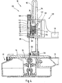
- the reference numeral 60 in FIG. 4 is an integrated into the housing block 42 Blowing device called.
- the latter is via a flexible pipeline 62 connected to a trained as a pipe shaft 64 on the guide shoe 28.
- This hollow shaft 64 is generated by the blowing device 60 Air fed into the guide shoe 28.
- From the guide shoe 28 enters the Blowing air via an air outlet 66 in the direction of the saw blade 26 from. She takes care of free view of the workpiece and the (pre-drawn) cutting line by the sawdust blows away from the interface.
- the hollow shaft 64 serves as a mounting shank of the guide shoe 28 is in a through hole height adjustable in the housing block 42 by means of a clamping screw attached, so that the height of the guide shoe 28 on the worktop 14 continuously adapted to the thickness of the workpiece to be sawn can be.
- the blowing device 60 comprises a bellows 70 which in a chamber 72nd the housing block 42 is installed.
- One end of the bellows 70 is with a Air outlet 74 connected to the flexible pipe 62 connected is.
- the other end of the bellows 70 is provided with a header 76 closed, in the chamber 72 parallel to the lifting movement of the lifting pin 44 is slidably guided.
- this head piece 76 is a check valve 78th built-in.
- a connecting device 80 connects the head part 76 with the Lifting pin 44. If the lifting pin 44 is moved downward, the bellows 70 expanded and air flows through the check valve 78 in the bellows 70 a. If the lifting pin is moved upward, the air in the bellows 70 is compressed.
- the serving as a check valve ball 78 is in this case in their seat pressed so that the compressed air, the bellows 70 via the air outlet 74 must leave.
Landscapes
- Engineering & Computer Science (AREA)
- Mechanical Engineering (AREA)
- Sawing (AREA)
- Valve Device For Special Equipments (AREA)
- Dry Shavers And Clippers (AREA)
Description
- Figur 1:
- eine perspektivische Ansicht einer erfindungsgemäßen Dekupiersäge in einer ersten Arbeitsstellung;
- Figur 2:
- eine perspektivische Ansicht der Dekupiersäge nach Figur 1, in einer zweiten Arbeitsstellung;
- Figur 3:
- eine Explosionszeichnung der unteren Sägeblatt-Einspanneinheit der Dekupiersäge nach Figur 1;
- Figur 4:
- einen Schnitt durch eine vorteilhafte Ausgestaltung einer erfindungsgemäßen Dekupiersäge.
Claims (8)
- Dekupiersäge, umfassend:dadurch gekennzeichnet, daßeine Tragstruktur (12) zum Aufstellen der Dekupiersäge;eine Arbeitsplatte (14) die von der Tragstruktur (12) getragen wird;einen Sägearm (18) der von der Tragstruktur (12) getragen wird und sichüber die Arbeitsplatte (14) erstreckt, wo er eine vertikale Führungsschiene ausbildet;eine obere Sägeblatt-Einspanneinheit (22) mit einem Gehäuseblock (42) der an der vertikalen Führungsschiene des Sägearms (18) in unterschiedlichen Höhen festklemmbar ist;eine untere Sägeblatt-Einspanneinheit (24) die unterhalb der Arbeitsplatte (14) angeordnet ist;ein Sägeblatt (26) das in der unteren und oberen Sägeblatt-Einspanneinheit (22 und 24) eingespannt ist und sich durch eine Öffnung in der Arbeitsplatte (14) erstreckt; undeinen Antrieb (30) zum Erzeugen einer alternierenden Hubbewegung des Sägeblattes (26);
die Führungsschiene durch ein senkrechtes Winkelprofil (54) mit einem seitlichen Flansch ausgebildet wird, und der Gehäuseblock (42) in unterschiedlichen Höhen an diesem seitlichen Flansch des Winkelprofils (54) festklemmbar ist, so dass unterschiedliche Einspannlängen für das Sägeblatt eingestellt werden können. - Dekupiersäge nach Anspruch 1, dadurch gekennzeichnet, daß der Gehäuseblock (42) an dem seitlichen Flansch des Winkelprofils (54) stufenlos festklemmbar ist.
- Dekupiersäge nach einem der Ansprüche 1 oder 2, dadurch gekennzeichnet, daß mindestens eine Sägeblatt-Einspanneinheit (22, 24) eine Klemmvorrichtung (40) für die Befestigung des Sägeblattes (26) aufweist.
- Dekupiersäge nach einem der Ansprüche 1 bis 3, dadurch gekennzeichnet, daß
die untere Sägeblatt-Einspanneinheit (24) den Hubantrieb (30) umfaßt, und
in den Gehäuseblock (42) ein passiver Hubteil integriert ist, wobei das obere Ende des Sägeblattes (26) an diesem passiven Hubteil befestigt ist. - Dekupiersäge nach Anspruch 4, dadurch gekennzeichnet, daß der passive Hubteil einen Hubstift (44), mindestens eine Führungsbuchse (46, 47) für den Hubstift (44), und eine Gegenfeder (48) aufweist, wobei das obere Ende des Sägeblattes (26) an dem Hubstift (44) befestigt ist.
- Dekupiersäge nach Anspruch 4 oder 5, dadurch gekennzeichnet, daß in den Gehäuseblock (42) weiterhin eine Spannschraube (50) für das Sägeblatt (26) integriert ist.
- Dekupiersäge nach einem der Ansprüche 1 bis 6, dadurch gekennzeichnet, daß in die obere Sägeblatt-Einspanneinheit (22) ein Blasebalg (70) derart eingebaut ist, daß er durch die alternierende Hubbewegung des Sägeblatts (26) betätigt wird.
- Dekupiersäge nach Anspruch 7, gekennzeichnet durch einen Führungsschuh (28) mit einem als Rohr ausgebildeten Schaft (64), der mit dem Blasebalg (70) verbunden ist, wobei der Führungsschuh (28) einen Luftauslaß (66) in Richtung Sägeblatt 26 aufweist.
Applications Claiming Priority (2)
| Application Number | Priority Date | Filing Date | Title |
|---|---|---|---|
| LU90272 | 1998-08-05 | ||
| LU90272 | 1998-08-05 |
Publications (3)
| Publication Number | Publication Date |
|---|---|
| EP0978341A2 EP0978341A2 (de) | 2000-02-09 |
| EP0978341A3 EP0978341A3 (de) | 2002-04-24 |
| EP0978341B1 true EP0978341B1 (de) | 2005-08-24 |
Family
ID=19731760
Family Applications (1)
| Application Number | Title | Priority Date | Filing Date |
|---|---|---|---|
| EP99107604A Expired - Lifetime EP0978341B1 (de) | 1998-08-05 | 1999-04-16 | Dekupiersäge |
Country Status (3)
| Country | Link |
|---|---|
| EP (1) | EP0978341B1 (de) |
| AT (1) | ATE302663T1 (de) |
| DE (1) | DE59912453D1 (de) |
Families Citing this family (1)
| Publication number | Priority date | Publication date | Assignee | Title |
|---|---|---|---|---|
| CN107088677B (zh) * | 2017-05-31 | 2018-05-22 | 盐城市诚益通机械制造有限责任公司 | 一种工程施工用金属板切割机 |
Family Cites Families (5)
| Publication number | Priority date | Publication date | Assignee | Title |
|---|---|---|---|---|
| DE68662C (de) * | F. W. MÜLLER JUN. in Berlin S.O., Mariannenstr. 31/32 | Laubsäge | ||
| US1467720A (en) * | 1921-06-25 | 1923-09-11 | Wm A Field Company | Jig saw |
| US2165002A (en) * | 1937-05-20 | 1939-07-04 | Walker Turner Co Inc | Tensioning means for running jigsaws |
| US2327239A (en) * | 1941-12-12 | 1943-08-17 | Herbert R Bartlett | Jigsaw |
| DE3930532C1 (en) * | 1989-09-13 | 1991-02-28 | Reinhard 7000 Stuttgart De Becher | Fret saw with saw blade end clamped in bracket - has other blade end non-rotatably clamp by retainer, with both blade ends mutually twisted |
-
1999
- 1999-04-16 DE DE59912453T patent/DE59912453D1/de not_active Expired - Lifetime
- 1999-04-16 EP EP99107604A patent/EP0978341B1/de not_active Expired - Lifetime
- 1999-04-16 AT AT99107604T patent/ATE302663T1/de not_active IP Right Cessation
Also Published As
| Publication number | Publication date |
|---|---|
| EP0978341A3 (de) | 2002-04-24 |
| DE59912453D1 (de) | 2005-09-29 |
| EP0978341A2 (de) | 2000-02-09 |
| ATE302663T1 (de) | 2005-09-15 |
Similar Documents
| Publication | Publication Date | Title |
|---|---|---|
| EP0163185B1 (de) | Stichsäge | |
| EP0736353B1 (de) | Stichsäge | |
| DE3509515C2 (de) | ||
| DE4403186B4 (de) | Handkreissäge mit Pendelschutzhaube und mit einer Gehrungswinkel-Einstellvorrichtung | |
| DE3022493A1 (de) | Motorbetriebene stossaege mit langgestrecktem saegeblatt | |
| EP1753579A1 (de) | Universalsäge | |
| DE3912307C2 (de) | ||
| DE3635159C2 (de) | Handwerkzeugmaschine mit einer Auflageplatte und einem Parallelanschlag | |
| EP0012257A1 (de) | Schutzvorrichtung für das Kreissägeblatt von Kreissägemaschinen mit vertikal beweglichem Sägeaggregat | |
| EP0446456B1 (de) | Pendelhubsäge | |
| EP0215073B2 (de) | Stichsäge | |
| DE19513077B4 (de) | Stichsäge | |
| EP1466690A1 (de) | Säbelsäge mit Justiervorrichtung für eine Führungsvorrichtung | |
| DE10055049C1 (de) | Vorrichtung zur Aufhängung eines Sägeblattes in einer Parallelogramm-Dekupiersäge | |
| EP0978341A2 (de) | Dekupiersäge | |
| EP1466689A1 (de) | Säbelsäge mit Führungsvorrichtung | |
| DE19507286C2 (de) | Abrichtlinealführung für motorbetriebene Werkzeuge | |
| DE202004019137U1 (de) | Kapp- und Tischkreissäge | |
| WO2022226558A1 (de) | Kettenfräsvorrichtung mit splitterschutz zum fräsen einer taschenförmigen ausnehmung in einem werkstück | |
| DE9315498U1 (de) | Hubsäge | |
| DE19521247C2 (de) | Stichsäge mit Sägeblatt mit Wellrücken | |
| EP1066905B1 (de) | Stichsäge mit Sägeblattführungvorrichtung | |
| AT525009B1 (de) | Kettenfräsvorrichtung mit Anschlagelementen zum Fräsen einer taschenförmigen Ausnehmung in einem Werkstück | |
| DE19502469B4 (de) | Stationäre Stichsäge mit Absaugvorrichtung | |
| DE3420183A1 (de) | Halterung fuer den spaltkeil einer zerspanenden bearbeitungsmaschine |
Legal Events
| Date | Code | Title | Description |
|---|---|---|---|
| PUAI | Public reference made under article 153(3) epc to a published international application that has entered the european phase |
Free format text: ORIGINAL CODE: 0009012 |
|
| AK | Designated contracting states |
Kind code of ref document: A2 Designated state(s): AT BE CH CY DE DK ES FI FR GB GR IE IT LI LU MC NL PT SE Kind code of ref document: A2 Designated state(s): AT DE FR GB |
|
| AX | Request for extension of the european patent |
Free format text: AL;LT;LV;MK;RO;SI |
|
| PUAL | Search report despatched |
Free format text: ORIGINAL CODE: 0009013 |
|
| AK | Designated contracting states |
Kind code of ref document: A3 Designated state(s): AT BE CH CY DE DK ES FI FR GB GR IE IT LI LU MC NL PT SE |
|
| AX | Request for extension of the european patent |
Free format text: AL;LT;LV;MK;RO;SI |
|
| 17P | Request for examination filed |
Effective date: 20021014 |
|
| AKX | Designation fees paid |
Free format text: AT DE FR GB |
|
| 17Q | First examination report despatched |
Effective date: 20030207 |
|
| GRAP | Despatch of communication of intention to grant a patent |
Free format text: ORIGINAL CODE: EPIDOSNIGR1 |
|
| GRAS | Grant fee paid |
Free format text: ORIGINAL CODE: EPIDOSNIGR3 |
|
| GRAA | (expected) grant |
Free format text: ORIGINAL CODE: 0009210 |
|
| AK | Designated contracting states |
Kind code of ref document: B1 Designated state(s): AT DE FR GB |
|
| PG25 | Lapsed in a contracting state [announced via postgrant information from national office to epo] |
Ref country code: GB Free format text: LAPSE BECAUSE OF FAILURE TO SUBMIT A TRANSLATION OF THE DESCRIPTION OR TO PAY THE FEE WITHIN THE PRESCRIBED TIME-LIMIT Effective date: 20050824 |
|
| REG | Reference to a national code |
Ref country code: GB Ref legal event code: FG4D Free format text: NOT ENGLISH |
|
| REF | Corresponds to: |
Ref document number: 59912453 Country of ref document: DE Date of ref document: 20050929 Kind code of ref document: P |
|
| GBV | Gb: ep patent (uk) treated as always having been void in accordance with gb section 77(7)/1977 [no translation filed] |
Effective date: 20050824 |
|
| PG25 | Lapsed in a contracting state [announced via postgrant information from national office to epo] |
Ref country code: AT Free format text: LAPSE BECAUSE OF NON-PAYMENT OF DUE FEES Effective date: 20060416 |
|
| PLBE | No opposition filed within time limit |
Free format text: ORIGINAL CODE: 0009261 |
|
| STAA | Information on the status of an ep patent application or granted ep patent |
Free format text: STATUS: NO OPPOSITION FILED WITHIN TIME LIMIT |
|
| 26N | No opposition filed |
Effective date: 20060526 |
|
| EN | Fr: translation not filed | ||
| PG25 | Lapsed in a contracting state [announced via postgrant information from national office to epo] |
Ref country code: FR Free format text: LAPSE BECAUSE OF FAILURE TO SUBMIT A TRANSLATION OF THE DESCRIPTION OR TO PAY THE FEE WITHIN THE PRESCRIBED TIME-LIMIT Effective date: 20061020 |
|
| PG25 | Lapsed in a contracting state [announced via postgrant information from national office to epo] |
Ref country code: FR Free format text: LAPSE BECAUSE OF FAILURE TO SUBMIT A TRANSLATION OF THE DESCRIPTION OR TO PAY THE FEE WITHIN THE PRESCRIBED TIME-LIMIT Effective date: 20050824 |
|
| PGFP | Annual fee paid to national office [announced via postgrant information from national office to epo] |
Ref country code: DE Payment date: 20180215 Year of fee payment: 20 |
|
| REG | Reference to a national code |
Ref country code: DE Ref legal event code: R071 Ref document number: 59912453 Country of ref document: DE |