EP0978250A2 - A device for drying the dishes at the end of the washing process of a dishwasher - Google Patents
A device for drying the dishes at the end of the washing process of a dishwasher Download PDFInfo
- Publication number
- EP0978250A2 EP0978250A2 EP99115218A EP99115218A EP0978250A2 EP 0978250 A2 EP0978250 A2 EP 0978250A2 EP 99115218 A EP99115218 A EP 99115218A EP 99115218 A EP99115218 A EP 99115218A EP 0978250 A2 EP0978250 A2 EP 0978250A2
- Authority
- EP
- European Patent Office
- Prior art keywords
- duct
- tank
- dishwasher
- outlet
- dishes
- Prior art date
- Legal status (The legal status is an assumption and is not a legal conclusion. Google has not performed a legal analysis and makes no representation as to the accuracy of the status listed.)
- Withdrawn
Links
- 238000005406 washing Methods 0.000 title claims abstract description 15
- 238000001035 drying Methods 0.000 title claims abstract description 14
- 239000000203 mixture Substances 0.000 claims abstract description 19
- 238000001816 cooling Methods 0.000 claims 3
- 239000012809 cooling fluid Substances 0.000 claims 2
- XLYOFNOQVPJJNP-UHFFFAOYSA-N water Substances O XLYOFNOQVPJJNP-UHFFFAOYSA-N 0.000 description 17
- 239000000463 material Substances 0.000 description 4
- 238000000034 method Methods 0.000 description 3
- 238000004519 manufacturing process Methods 0.000 description 2
- 239000012782 phase change material Substances 0.000 description 2
- 238000006424 Flood reaction Methods 0.000 description 1
- 238000006243 chemical reaction Methods 0.000 description 1
- 238000004851 dishwashing Methods 0.000 description 1
- 239000000428 dust Substances 0.000 description 1
- 238000001704 evaporation Methods 0.000 description 1
- 230000008020 evaporation Effects 0.000 description 1
- 239000012530 fluid Substances 0.000 description 1
- 230000005484 gravity Effects 0.000 description 1
- 230000017525 heat dissipation Effects 0.000 description 1
- 238000010438 heat treatment Methods 0.000 description 1
- 239000012188 paraffin wax Substances 0.000 description 1
- 125000002467 phosphate group Chemical class [H]OP(=O)(O[H])O[*] 0.000 description 1
- 238000009423 ventilation Methods 0.000 description 1
- 239000001993 wax Substances 0.000 description 1
Images
Classifications
-
- A—HUMAN NECESSITIES
- A47—FURNITURE; DOMESTIC ARTICLES OR APPLIANCES; COFFEE MILLS; SPICE MILLS; SUCTION CLEANERS IN GENERAL
- A47L—DOMESTIC WASHING OR CLEANING; SUCTION CLEANERS IN GENERAL
- A47L15/00—Washing or rinsing machines for crockery or tableware
- A47L15/42—Details
- A47L15/48—Drying arrangements
- A47L15/483—Drying arrangements by using condensers
-
- A—HUMAN NECESSITIES
- A47—FURNITURE; DOMESTIC ARTICLES OR APPLIANCES; COFFEE MILLS; SPICE MILLS; SUCTION CLEANERS IN GENERAL
- A47L—DOMESTIC WASHING OR CLEANING; SUCTION CLEANERS IN GENERAL
- A47L15/00—Washing or rinsing machines for crockery or tableware
- A47L15/42—Details
- A47L15/48—Drying arrangements
- A47L15/481—Drying arrangements by using water absorbent materials, e.g. Zeolith
Definitions
- the present invention refers to a device for drying the dishes at the end of the washing process of a dishwasher.
- said steam In order to condense the steam contained in the air, said steam has to transfer heat to a body at a temperature lower than the dew point temperature of the air-steam mixture.
- Some manufacturers use electric resistors to heat the air inside the dishwasher and therefore to lower the relative humidity, in order to enhance the drying process.
- the disadvantage of said process is the significant consumption of electric energy. Then, the normal heat dissipation towards the outside environment causes the decrease of the temperature of the tank walls and the condensing of the steam on said walls.
- the purpose of the present invention is to realise a device to enhance the drying process of the dishes at the end of the washing process of a dishwasher, said device being free from the above described disadvantages.
- a device for drying the dishes at the end of the washing process of a dishwasher is characterised by comprising a condensing duct connected, at its inlet and outlet sections, to the washing tank of the dishwasher, a forced conduction device of an air-steam mixture along said duct, and heat exchange means positioned along the duct, and maintained at a temperature substantially lower than the dew point temperature of said mixture.
- numeral 1 indicates, as a whole, a device for drying the dishes at the end of the washing process of a dishwasher 10.
- the device 1 comprises a condensing duct 11 which extends outside a dish washing tank 12, and said duct is fully positioned inside the dishwasher 10, and an electric fan 13 suitable to feed an air-steam mixture 14 along said duct 11.
- the duct 11 comprises an inlet 11i and an outlet 11u directly connected to the tank 12, while the electric fan comprises a fan 30 positioned within the duct 11, substantially at the outlet 11u or along said duct 11, and a driving motor 31 suitable to rotate the fan 30 so as to draw the mixture 14 from the tank 12 and to make said mixture advance in a feed direction D along said duct 11.
- the device 1 further comprises a water tank 16, which is suitable to be filled with a certain amount of water at the beginning of the drying process, and which is provided with a heat exchange wall 15 positioned inside the duct 11, and maintained at a temperature lower than the dew point temperature of the air by said water.
- the heat exchange between the mixture 14, which circulates inside the duct 11, and the wall 15 causes the condensing of at least a portion of the steam of said mixture 14.
- the size of said tank 16 is a function of the amount of steam which needs to be condensed; in fact, since the device 1 is a closed device, i.e. a device which does not have any outside emissions, said device works by using the water thermal capacity in order to accumulate the steam condensing energy.
- the wall 15 has a sufficiently reduced thickness, while the corresponding exchange surface 15s which faces the inside of the duct 11 has an elevated exchange area.
- the surface 15s has a bellows-like shape, but it can have any other shape and it can be realised with any kind of material.
- the tank 16 can contain other materials as, for instance, waxes, paraffin, some phosphate salts, PCM ( Phase Change Material ), which allow to accumulate heat through physical changes or through endothermic chemical reactions.
- PCM Phase Change Material
- the device 1 comprises a feed opening 17 to feed cool water to the tank 16, and a discharge opening 19 to discharge the heated water from said tank 16; while the duct 11 is provided with a discharge outlet 18 for the condensate, which is collected by the gravity force from the surface 15s at said discharge outlet 18.
- the discharge outlet 18 is connected alternatively to a small well (not shown) in the dishwasher 10, or directly to the tank 12, and, in this case, in order to avoid flooding the duct 11 with the washing water, the discharge outlet 18 is provided with a stop solenoid valve (not shown and of a known type), or with a float (not shown and of a known type) suitable to automatically close said discharge outlet 18.
- the tank 16 could also be defined by a bag 20 hermetically sealed placed inside the duct 11 and which is not in contact with said duct 11 so as to have its outer surface 15s fully surrounded by the mixture 14.
- the air-steam mixture at the outlet 11u of the condensing duct 11 has a lower steam content with respect to the inlet conditions into said duct 11.
- the position of the electric fan 13 used to circulate the air is also important, in fact, by placing the electric fan 13 at the outlet 11u of the condensing duct 11, it is possible to maintain the pressure inside said duct 11 at a value lower than the value of the environment pressure because of the normal pressure drops inside the ducts: this fact further enhances the condensing since the pressure value influences the saturation temperature. Further, by placing also the motor 31 inside the duct 11 and by making the air, before it goes back into the tank 12 of the dishwasher 10, get in touch and cool said motor 31, a partial heating of the air itself is obtained with a consequent further decrease of the relative humidity. The power dissipated by the motor 31 is therefore used to further enhance the drying process.
- the electric fan 13 can be placed at any point of the duct 11, according to the production needs, without, for this reason, significantly jeopardising the just described advantages with respect to the positioning of said electric fan 13 at the outlet 11u.
- Figures 4, 5 and 6 show a preferred embodiment of the device 1, wherein, for reasons of overall dimensions, the duct 11 is mounted laterally and below the tank 12, and the electric fan 13 is placed inside the duct 11 and directly below the tank 12.
- the inlet 11i is provided with a vertical siphon 51, while the outlet 11u is provided with a corresponding vertical siphon 52, which is positioned on the same plane of the siphon 51 and the mixture 14 passes vertically through said siphon 52 to reduce its speed and to enhance the heat exchange with the wall 15, which defines a rear wall both for the siphon 51 and for the siphon 52.
- At least the fan 30 of the electric fan 31 is enclosed in a fluid tight box 53, which defines an intermediate portion of the duct 11, and it is positioned below the tank 12, and it comprises an elbow shaped inlet 53i connected to the siphon 52 in order to fully insulate said electric fan 13 from the tank 12.
- Said box comprises two side appendices, wherein the appendix 54 defines an elbow shaped inlet duct for the siphon 51, while the appendix 55 has an inlet duct 56 and an outlet duct 57 of the water from the tank 16.
- the siphon 51 is substantially U-shaped and has its concave portion facing downward
- the siphon 52 has substantially an upside-down L shape and extends from the outlet 53u until it reaches the outlet 11u, and it is provided with a plurality of inner bent tiles 58 suitable to obstruct the free flow of the mixture 14.
- the fan 30 is a fan which has an axial inlet flow and a radial outlet flow in order to feed both the outlet 53u and the appendix 54 so as to enhance the circulation of the mixture 14 along the duct 11.
Abstract
Description
- The present invention refers to a device for drying the dishes at the end of the washing process of a dishwasher.
- At the end of the washing process of a dishwasher, in order to dry the dishes, it is necessary to evaporate the water left on said dishes, and it is necessary that the following conditions are met:
- a) the air within the dishwasher must have a steam content lower than the saturation level;
- b) the water on the dishes must have a temperature higher than the dew point temperature of the air.
-
- Therefrom, the need to reduce the steam content of the air or to heat the air or to substitute the air contained in the dishwasher with other air having a lower steam content.
- In order to condense the steam contained in the air, said steam has to transfer heat to a body at a temperature lower than the dew point temperature of the air-steam mixture.
- Some manufacturers use electric resistors to heat the air inside the dishwasher and therefore to lower the relative humidity, in order to enhance the drying process.
- The disadvantage of said process is the significant consumption of electric energy. Then, the normal heat dissipation towards the outside environment causes the decrease of the temperature of the tank walls and the condensing of the steam on said walls.
- Other manufacturers use fans to draw the steam from the dishwasher and to send it into the outside environment; the so expelled air-steam mixture is substituted with outside air which contains dust which can dirty the dishes.
- Another disadvantage of this process is the introduction of steam and of odours into the environment.
- Further, this type of process is not suitable with the integral built-in dishwashers in the kitchen furniture.
- Other manufacturers use cold water in order to cool one or more inside walls of the dishwasher whereon the steam can condense; this solution has the advantage that it does not consume any amount of energy, but the lack of ventilation obstructs the water evaporation from the dishes, since the air moves only because of weak convective movements caused by the different temperatures on the various tank walls.
- The purpose of the present invention is to realise a device to enhance the drying process of the dishes at the end of the washing process of a dishwasher, said device being free from the above described disadvantages.
- According to the present invention, a device for drying the dishes at the end of the washing process of a dishwasher is realised, said device is characterised by comprising a condensing duct connected, at its inlet and outlet sections, to the washing tank of the dishwasher, a forced conduction device of an air-steam mixture along said duct, and heat exchange means positioned along the duct, and maintained at a temperature substantially lower than the dew point temperature of said mixture.
- The invention will now be described making reference to the attached drawings, which describe a non limiting example of an embodiment, wherein:
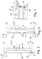
- figure 1 shows, in a schematic way, a dishwasher provided with a first preferred embodiment of the device according to the invention;
- figure 2 is a schematic side elevation view of the device of figure 1;
- figure 3 is a schematic side elevation view of a second preferred embodiment of the device of figure 1;
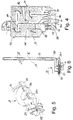
- figure 4 is a front view of a third type of embodiment of the device of figure 1, said view has sectional views of some of the parts and some exploded parts for clarity sake;
- figure 5 is an enlarged perspective view, with some exploded parts for clarity sake, of a detail of figure 4; and
- figure 6 is a side elevation view of the device of figure 4, said view has sectional views of some of the parts and some exploded parts for clarity sake.
- Referring to figure 1,
numeral 1 indicates, as a whole, a device for drying the dishes at the end of the washing process of a dishwasher 10. - The
device 1 comprises acondensing duct 11 which extends outside adish washing tank 12, and said duct is fully positioned inside the dishwasher 10, and anelectric fan 13 suitable to feed an air-steam mixture 14 along saidduct 11. - The
duct 11 comprises an inlet 11i and an outlet 11u directly connected to thetank 12, while the electric fan comprises afan 30 positioned within theduct 11, substantially at the outlet 11u or along saidduct 11, and adriving motor 31 suitable to rotate thefan 30 so as to draw themixture 14 from thetank 12 and to make said mixture advance in a feed direction D along saidduct 11. - The
device 1 further comprises awater tank 16, which is suitable to be filled with a certain amount of water at the beginning of the drying process, and which is provided with aheat exchange wall 15 positioned inside theduct 11, and maintained at a temperature lower than the dew point temperature of the air by said water. The heat exchange between themixture 14, which circulates inside theduct 11, and thewall 15 causes the condensing of at least a portion of the steam of saidmixture 14. - The size of said
tank 16 is a function of the amount of steam which needs to be condensed; in fact, since thedevice 1 is a closed device, i.e. a device which does not have any outside emissions, said device works by using the water thermal capacity in order to accumulate the steam condensing energy. - If the overall dimensions do not allow a sufficient water capacity, it is possible to divide the drying process by changing one or more times the warmed up water load of the
tank 16 with cool water. - In order to enhance the heat exchange, the
wall 15 has a sufficiently reduced thickness, while the corresponding exchange surface 15s which faces the inside of theduct 11 has an elevated exchange area. In the non limiting example of embodiment shown in figure 2, the surface 15s has a bellows-like shape, but it can have any other shape and it can be realised with any kind of material. - As an alternative to water, the
tank 16 can contain other materials as, for instance, waxes, paraffin, some phosphate salts, PCM (Phase Change Material), which allow to accumulate heat through physical changes or through endothermic chemical reactions. - No replacement is provided for these materials inside the
tank 16, and the heat accumulated in said materials to maintain thewall 15 at a temperature lower than the dew point temperature of the air is transferred to the outside environment during the rest period of the dishwasher 10 between the washing cycles, and, in order to enhance the heat exchange between the outside environment and thetank 16, the latter can be installed, for instance, in an opening (not shown) of the dishwasher 10. - Further, the
device 1 comprises afeed opening 17 to feed cool water to thetank 16, and a discharge opening 19 to discharge the heated water from saidtank 16; while theduct 11 is provided with adischarge outlet 18 for the condensate, which is collected by the gravity force from the surface 15s at saiddischarge outlet 18. - The
discharge outlet 18 is connected alternatively to a small well (not shown) in the dishwasher 10, or directly to thetank 12, and, in this case, in order to avoid flooding theduct 11 with the washing water, thedischarge outlet 18 is provided with a stop solenoid valve (not shown and of a known type), or with a float (not shown and of a known type) suitable to automatically close saiddischarge outlet 18. - According to what is shown in figure 3, the
tank 16 could also be defined by abag 20 hermetically sealed placed inside theduct 11 and which is not in contact with saidduct 11 so as to have its outer surface 15s fully surrounded by themixture 14. - Because of the partial condensing of the steam, the air-steam mixture at the outlet 11u of the
condensing duct 11 has a lower steam content with respect to the inlet conditions into saidduct 11. - The position of the
electric fan 13 used to circulate the air is also important, in fact, by placing theelectric fan 13 at the outlet 11u of thecondensing duct 11, it is possible to maintain the pressure inside saidduct 11 at a value lower than the value of the environment pressure because of the normal pressure drops inside the ducts: this fact further enhances the condensing since the pressure value influences the saturation temperature. Further, by placing also themotor 31 inside theduct 11 and by making the air, before it goes back into thetank 12 of the dishwasher 10, get in touch and cool saidmotor 31, a partial heating of the air itself is obtained with a consequent further decrease of the relative humidity. The power dissipated by themotor 31 is therefore used to further enhance the drying process. - However, the
electric fan 13 can be placed at any point of theduct 11, according to the production needs, without, for this reason, significantly jeopardising the just described advantages with respect to the positioning of saidelectric fan 13 at the outlet 11u. - Figures 4, 5 and 6 show a preferred embodiment of the
device 1, wherein, for reasons of overall dimensions, theduct 11 is mounted laterally and below thetank 12, and theelectric fan 13 is placed inside theduct 11 and directly below thetank 12. - In particular, in order to avoid at the same time that the washing water floods the
duct 11, the inlet 11i is provided with a vertical siphon 51, while the outlet 11u is provided with a correspondingvertical siphon 52, which is positioned on the same plane of the siphon 51 and themixture 14 passes vertically through saidsiphon 52 to reduce its speed and to enhance the heat exchange with thewall 15, which defines a rear wall both for the siphon 51 and for thesiphon 52. - The fact that the two
siphons 51 and 52 are integral with thewall 15 allows to take the best advantage of the available room by reducing to the minimum requirements the overall dimensions of thedevice 1. - At least the
fan 30 of theelectric fan 31 is enclosed in a fluidtight box 53, which defines an intermediate portion of theduct 11, and it is positioned below thetank 12, and it comprises an elbow shaped inlet 53i connected to thesiphon 52 in order to fully insulate saidelectric fan 13 from thetank 12. - Said box comprises two side appendices, wherein the
appendix 54 defines an elbow shaped inlet duct for the siphon 51, while theappendix 55 has aninlet duct 56 and anoutlet duct 57 of the water from thetank 16. In particular, the siphon 51 is substantially U-shaped and has its concave portion facing downward, while thesiphon 52 has substantially an upside-down L shape and extends from the outlet 53u until it reaches the outlet 11u, and it is provided with a plurality ofinner bent tiles 58 suitable to obstruct the free flow of themixture 14. - In the example of embodiment shown in figures 4, 5 and 6, the
fan 30 is a fan which has an axial inlet flow and a radial outlet flow in order to feed both the outlet 53u and theappendix 54 so as to enhance the circulation of themixture 14 along theduct 11. - It is understood that the invention is not limited by the herein described and shown embodiments, which have to be considered as realisation examples of the
device 1 for the drying process of the dishes, which is instead suitable for further changes with respect to part shapes and to part positioning, and to production and assembly details.
Claims (13)
- A device for drying the dishes at the end of the washing process of a dishwasher (10), said device (1) is characterised by comprising a condensing duct (11) connected, at its inlet and outlet sections, to the washing tank (12) of the dishwasher (10), a forced conduction device (13) of an air-steam mixture (14) along said duct (10), and heat exchange means (15) positioned along the duct (11), wherein said heat exchange means are maintained at a temperature substantially lower than the dew point temperature of said mixture (14).
- A device as claimed in claim 1, characterised in that said fan (30) is positioned inside the duct (11).
- A device as claimed in claim 1 or 2, characterised in that said forced conduction device (13) comprises a fan (30) positioned substantially at one outlet (11u) of said duct (11).
- A device as claimed in claim 1 or 2, characterised in that the duct (11) comprises an intermediate portion (53) positioned below said tank (12); said fan (30) is positioned inside said intermediate portion (53).
- A device as claimed in claim 2 or 3, characterised in that said forced conduction device (13) comprises a motor (30) to drive said fan (31), the motor (30) is positioned inside said duct (11) substantially at said outlet (11u).
- A device as claimed in claim 4 or 5, characterised in that said device (13) comprises at least a siphon (51) integral with said device (13) positioned at said inlet (11i).
- A device as claimed in any of the previous claims, characterised in that said heat exchange means (15) comprise an exchange surface (15s) fully positioned inside the duct (11), and cooling means (16)(20) of said exchange surface (15s) in order to maintain the exchange surface (15s) at a temperature lower than the dew point temperature of said mixture (14).
- A device as claimed in claim 7, characterised in that said cooling means (16)(20) are defined by a tank (16)(20) suitable to receive, at the beginning of each drying process, a certain amount of cooling fluid; said exchange surface (15s) is an outer wall of said tank (16)(20).
- A device as claimed in claim 7, characterised in that said cooling means (16)(20) are defined by a tank (16)(20) which contains a defined amount of cooling fluid; said exchange surface (15s) is an outer wall of said tank (16)(20).
- A device as claimed in claim 8, characterised in that said tank (20) is defined by an envelope (20) fully positioned inside said duct (11) in a position detached from said duct (11).
- A device as claimed in any of the previous claims, characterised in that said duct (11) comprises a discharge outlet (18) to expel the condensed steam from said duct (11).
- A device as claimed in any of the previous claims, characterised in that said duct (11) is fully positioned inside said dishwasher (10).
- A device for drying the dishes at the end of the washing process of a dishwasher, substantially as it has been described with reference to any of the attached drawings.
Applications Claiming Priority (2)
| Application Number | Priority Date | Filing Date | Title |
|---|---|---|---|
| IT1998TO000686A IT1303213B1 (en) | 1998-08-06 | 1998-08-06 | DISHWASHER DRYING DEVICE AT THE END OF THE DISHWASHER WASHING PROCESS |
| ITTO980686 | 1998-08-06 |
Publications (2)
| Publication Number | Publication Date |
|---|---|
| EP0978250A2 true EP0978250A2 (en) | 2000-02-09 |
| EP0978250A3 EP0978250A3 (en) | 2000-11-22 |
Family
ID=11416981
Family Applications (1)
| Application Number | Title | Priority Date | Filing Date |
|---|---|---|---|
| EP99115218A Withdrawn EP0978250A3 (en) | 1998-08-06 | 1999-08-02 | A device for drying the dishes at the end of the washing process of a dishwasher |
Country Status (2)
| Country | Link |
|---|---|
| EP (1) | EP0978250A3 (en) |
| IT (1) | IT1303213B1 (en) |
Cited By (13)
| Publication number | Priority date | Publication date | Assignee | Title |
|---|---|---|---|---|
| FR2805729A1 (en) * | 2000-03-03 | 2001-09-07 | Aeg Hausgeraete Gmbh | DISHWASHER COMPRISING A CONDENSING DEVICE |
| EP1055389A3 (en) * | 1999-05-26 | 2002-05-08 | Miele & Cie. GmbH & Co. | Programmable dishwasher with device for drying the dishes |
| DE10013415B4 (en) * | 2000-03-03 | 2004-12-02 | AEG Hausgeräte GmbH | Dishwasher with a condensation device |
| DE10346304A1 (en) * | 2003-10-06 | 2005-04-28 | Bsh Bosch Siemens Hausgeraete | Dishwasher with drying device |
| EP1825800A3 (en) * | 2006-02-22 | 2008-05-14 | V-Zug AG | Dishwasher having a means for removing moisture from the tub |
| WO2008098745A2 (en) * | 2007-02-13 | 2008-08-21 | Meiko Maschinenbau Gmbh & Co. Kg | Front-load dishwasher machine with heat recovery |
| DE102007008827A1 (en) | 2007-02-22 | 2008-08-28 | Premark Feg L.L.C., Wilmington | Commercial dishwasher |
| DE102007008826A1 (en) | 2007-02-22 | 2008-08-28 | Premark Feg L.L.C., Wilmington | Commercial dishwashing machine and method of operation |
| WO2009074416A1 (en) * | 2007-12-11 | 2009-06-18 | BSH Bosch und Siemens Hausgeräte GmbH | Method for the drying time control in dishwashers |
| WO2010010166A1 (en) * | 2008-07-25 | 2010-01-28 | BSH Bosch und Siemens Hausgeräte GmbH | Washing method for a dishwashing machine |
| US7901518B2 (en) | 2005-05-20 | 2011-03-08 | Premark Feg L.L.C. | Commercial dishwasher with air deflector arrangement |
| ITTO20110985A1 (en) * | 2011-10-28 | 2013-04-29 | Bitron Spa | DRYING DEVICE FOR DISHWASHERS |
| WO2018104333A1 (en) | 2016-12-06 | 2018-06-14 | J.P.Industries S.P.A. | Machine for the drying of dishes or the like and method for the drying of dishes or the like with said machine. |
Citations (5)
| Publication number | Priority date | Publication date | Assignee | Title |
|---|---|---|---|---|
| FR1519571A (en) * | 1966-10-05 | 1968-04-05 | Household dryer for dishes, laundry and more, with automatic on and off | |
| GB2139083A (en) * | 1983-05-06 | 1984-11-07 | Bosch Siemens Hausgeraete | Waste heat utilisation in the operation of a dishwashing machine |
| DE3741652A1 (en) * | 1987-12-09 | 1989-06-22 | Bauknecht Hausgeraete | Device for drying dishes |
| EP0753282A1 (en) * | 1995-07-14 | 1997-01-15 | TECNOPLASTICA PREALPINA S.p.A. | A device for cooling and condensing the steam released from the washing drum of a dishwasher machine and the like |
| DE19622882A1 (en) * | 1996-06-07 | 1997-12-11 | Aeg Hausgeraete Gmbh | Dish washing appliance |
-
1998
- 1998-08-06 IT IT1998TO000686A patent/IT1303213B1/en active IP Right Grant
-
1999
- 1999-08-02 EP EP99115218A patent/EP0978250A3/en not_active Withdrawn
Patent Citations (5)
| Publication number | Priority date | Publication date | Assignee | Title |
|---|---|---|---|---|
| FR1519571A (en) * | 1966-10-05 | 1968-04-05 | Household dryer for dishes, laundry and more, with automatic on and off | |
| GB2139083A (en) * | 1983-05-06 | 1984-11-07 | Bosch Siemens Hausgeraete | Waste heat utilisation in the operation of a dishwashing machine |
| DE3741652A1 (en) * | 1987-12-09 | 1989-06-22 | Bauknecht Hausgeraete | Device for drying dishes |
| EP0753282A1 (en) * | 1995-07-14 | 1997-01-15 | TECNOPLASTICA PREALPINA S.p.A. | A device for cooling and condensing the steam released from the washing drum of a dishwasher machine and the like |
| DE19622882A1 (en) * | 1996-06-07 | 1997-12-11 | Aeg Hausgeraete Gmbh | Dish washing appliance |
Cited By (22)
| Publication number | Priority date | Publication date | Assignee | Title |
|---|---|---|---|---|
| EP1055389A3 (en) * | 1999-05-26 | 2002-05-08 | Miele & Cie. GmbH & Co. | Programmable dishwasher with device for drying the dishes |
| DE10013415B4 (en) * | 2000-03-03 | 2004-12-02 | AEG Hausgeräte GmbH | Dishwasher with a condensation device |
| FR2805729A1 (en) * | 2000-03-03 | 2001-09-07 | Aeg Hausgeraete Gmbh | DISHWASHER COMPRISING A CONDENSING DEVICE |
| DE10346304A1 (en) * | 2003-10-06 | 2005-04-28 | Bsh Bosch Siemens Hausgeraete | Dishwasher with drying device |
| US8887742B2 (en) | 2003-10-06 | 2014-11-18 | Bsh Bosch Und Siemens Hausgaraete Gmbh | Dishwasher comprising a drying apparatus |
| US7901518B2 (en) | 2005-05-20 | 2011-03-08 | Premark Feg L.L.C. | Commercial dishwasher with air deflector arrangement |
| EP1825800A3 (en) * | 2006-02-22 | 2008-05-14 | V-Zug AG | Dishwasher having a means for removing moisture from the tub |
| WO2008098745A2 (en) * | 2007-02-13 | 2008-08-21 | Meiko Maschinenbau Gmbh & Co. Kg | Front-load dishwasher machine with heat recovery |
| WO2008098745A3 (en) * | 2007-02-13 | 2009-01-22 | Meiko Maschinenbau Gmbh & Co | Front-load dishwasher machine with heat recovery |
| CN101248975B (en) * | 2007-02-22 | 2011-02-16 | 浦瑞玛柯Feg有限责任公司 | Commercial dishwasher |
| DE102007008827A1 (en) | 2007-02-22 | 2008-08-28 | Premark Feg L.L.C., Wilmington | Commercial dishwasher |
| DE102007008826A1 (en) | 2007-02-22 | 2008-08-28 | Premark Feg L.L.C., Wilmington | Commercial dishwashing machine and method of operation |
| US7875122B2 (en) | 2007-02-22 | 2011-01-25 | Premark Feg L.L.C. | Industrial dishwasher and method of operating the same |
| EP2289389A1 (en) * | 2007-12-11 | 2011-03-02 | BSH Bosch und Siemens Hausgeräte GmbH | Method for monitoring the drying period in dishwashers |
| US20100236575A1 (en) * | 2007-12-11 | 2010-09-23 | Bsh Bosch Und Siemens Hausgerate Gmbh | Method for the drying time control in dishwashers |
| CN101896113B (en) * | 2007-12-11 | 2013-04-10 | Bsh博世和西门子家用器具有限公司 | Method for the drying time control in dishwashers |
| WO2009074416A1 (en) * | 2007-12-11 | 2009-06-18 | BSH Bosch und Siemens Hausgeräte GmbH | Method for the drying time control in dishwashers |
| WO2010010166A1 (en) * | 2008-07-25 | 2010-01-28 | BSH Bosch und Siemens Hausgeräte GmbH | Washing method for a dishwashing machine |
| US9364133B2 (en) | 2008-07-25 | 2016-06-14 | BSH Hausgeräte GmbH | Washing method for a dishwashing machine |
| ITTO20110985A1 (en) * | 2011-10-28 | 2013-04-29 | Bitron Spa | DRYING DEVICE FOR DISHWASHERS |
| EP2586357A1 (en) * | 2011-10-28 | 2013-05-01 | Bitron S.p.A. | Drying device for a dishwasher |
| WO2018104333A1 (en) | 2016-12-06 | 2018-06-14 | J.P.Industries S.P.A. | Machine for the drying of dishes or the like and method for the drying of dishes or the like with said machine. |
Also Published As
| Publication number | Publication date |
|---|---|
| ITTO980686A0 (en) | 1998-08-06 |
| IT1303213B1 (en) | 2000-11-02 |
| EP0978250A3 (en) | 2000-11-22 |
| ITTO980686A1 (en) | 2000-02-06 |
Similar Documents
| Publication | Publication Date | Title |
|---|---|---|
| EP0978250A2 (en) | A device for drying the dishes at the end of the washing process of a dishwasher | |
| CN108078528B (en) | Drying device for dish-washing machine and dish-washing machine | |
| CN108209831B (en) | Drying device for a dishwasher and dishwasher | |
| CN111996770A (en) | Clothes nursing machine and self-cleaning control method thereof | |
| CN109974376A (en) | The return air grid and refrigerator of refrigerator | |
| CN206572649U (en) | A kind of reinforcing refrigeration outdoor unit of Split air conditioning system | |
| CN113639341B (en) | Dehumidification hot water unit based on three medium heat exchangers | |
| CN110906636A (en) | Refrigeration device | |
| JPH0387582A (en) | Drainage evaporating apparatus of refrigerator | |
| CN220345447U (en) | Dehumidification device and storage equipment | |
| CN218358374U (en) | Dehumidification module and storage equipment | |
| CN219846486U (en) | Cleaning machine | |
| CN103124889B (en) | Regenerative apparatus and the air conditioner possessing this regenerative apparatus | |
| CN218495398U (en) | Dehumidification heating module and storage equipment | |
| WO2015062661A1 (en) | Refrigeration appliance having an improved defrost water collection receptacle | |
| CN113124605A (en) | Refrigerator with frost reduction module and control method thereof | |
| CN217275043U (en) | Storage cabinet | |
| CN201104000Y (en) | Device for improving air conditioner refrigeration effect by condensation water | |
| CN215821751U (en) | Disinfection cabinet with quick drying function | |
| CN220494997U (en) | Cleaning machine | |
| CN216454322U (en) | Energy-saving heat radiator for condensed water of air curtain cabinet | |
| CN219780755U (en) | Heat exchanger and electronic cabinet | |
| CN212619125U (en) | Building air conditioner heat recovery system | |
| CN217274511U (en) | Mobile air conditioner | |
| CN112484177B (en) | Air conditioner |
Legal Events
| Date | Code | Title | Description |
|---|---|---|---|
| PUAI | Public reference made under article 153(3) epc to a published international application that has entered the european phase |
Free format text: ORIGINAL CODE: 0009012 |
|
| AK | Designated contracting states |
Kind code of ref document: A2 Designated state(s): AT BE CH CY DE DK ES FI FR GB GR IE IT LI LU MC NL PT SE |
|
| AX | Request for extension of the european patent |
Free format text: AL;LT;LV;MK;RO;SI |
|
| PUAL | Search report despatched |
Free format text: ORIGINAL CODE: 0009013 |
|
| AK | Designated contracting states |
Kind code of ref document: A3 Designated state(s): AT BE CH CY DE DK ES FI FR GB GR IE IT LI LU MC NL PT SE |
|
| AX | Request for extension of the european patent |
Free format text: AL;LT;LV;MK;RO;SI |
|
| AKX | Designation fees paid | ||
| REG | Reference to a national code |
Ref country code: DE Ref legal event code: 8566 |
|
| STAA | Information on the status of an ep patent application or granted ep patent |
Free format text: STATUS: THE APPLICATION IS DEEMED TO BE WITHDRAWN |
|
| 18D | Application deemed to be withdrawn |
Effective date: 20010523 |