EP0977607B1 - Dispositif d'inhalation - Google Patents
Dispositif d'inhalation Download PDFInfo
- Publication number
- EP0977607B1 EP0977607B1 EP98909952A EP98909952A EP0977607B1 EP 0977607 B1 EP0977607 B1 EP 0977607B1 EP 98909952 A EP98909952 A EP 98909952A EP 98909952 A EP98909952 A EP 98909952A EP 0977607 B1 EP0977607 B1 EP 0977607B1
- Authority
- EP
- European Patent Office
- Prior art keywords
- sealing surface
- cap
- grip portion
- lip
- housing
- Prior art date
- Legal status (The legal status is an assumption and is not a legal conclusion. Google has not performed a legal analysis and makes no representation as to the accuracy of the status listed.)
- Expired - Lifetime
Links
Images


Classifications
-
- A—HUMAN NECESSITIES
- A61—MEDICAL OR VETERINARY SCIENCE; HYGIENE
- A61M—DEVICES FOR INTRODUCING MEDIA INTO, OR ONTO, THE BODY; DEVICES FOR TRANSDUCING BODY MEDIA OR FOR TAKING MEDIA FROM THE BODY; DEVICES FOR PRODUCING OR ENDING SLEEP OR STUPOR
- A61M15/00—Inhalators
- A61M15/0065—Inhalators with dosage or measuring devices
-
- B—PERFORMING OPERATIONS; TRANSPORTING
- B65—CONVEYING; PACKING; STORING; HANDLING THIN OR FILAMENTARY MATERIAL
- B65D—CONTAINERS FOR STORAGE OR TRANSPORT OF ARTICLES OR MATERIALS, e.g. BAGS, BARRELS, BOTTLES, BOXES, CANS, CARTONS, CRATES, DRUMS, JARS, TANKS, HOPPERS, FORWARDING CONTAINERS; ACCESSORIES, CLOSURES, OR FITTINGS THEREFOR; PACKAGING ELEMENTS; PACKAGES
- B65D41/00—Caps, e.g. crown caps or crown seals, i.e. members having parts arranged for engagement with the external periphery of a neck or wall defining a pouring opening or discharge aperture; Protective cap-like covers for closure members, e.g. decorative covers of metal foil or paper
- B65D41/02—Caps or cap-like covers without lines of weakness, tearing strips, tags, or like opening or removal devices
- B65D41/04—Threaded or like caps or cap-like covers secured by rotation
- B65D41/0407—Threaded or like caps or cap-like covers secured by rotation with integral sealing means
-
- A—HUMAN NECESSITIES
- A61—MEDICAL OR VETERINARY SCIENCE; HYGIENE
- A61M—DEVICES FOR INTRODUCING MEDIA INTO, OR ONTO, THE BODY; DEVICES FOR TRANSDUCING BODY MEDIA OR FOR TAKING MEDIA FROM THE BODY; DEVICES FOR PRODUCING OR ENDING SLEEP OR STUPOR
- A61M15/00—Inhalators
- A61M15/0065—Inhalators with dosage or measuring devices
- A61M15/0068—Indicating or counting the number of dispensed doses or of remaining doses
- A61M15/007—Mechanical counters
- A61M15/0071—Mechanical counters having a display or indicator
- A61M15/0076—Mechanical counters having a display or indicator on a drum
-
- A—HUMAN NECESSITIES
- A61—MEDICAL OR VETERINARY SCIENCE; HYGIENE
- A61M—DEVICES FOR INTRODUCING MEDIA INTO, OR ONTO, THE BODY; DEVICES FOR TRANSDUCING BODY MEDIA OR FOR TAKING MEDIA FROM THE BODY; DEVICES FOR PRODUCING OR ENDING SLEEP OR STUPOR
- A61M2202/00—Special media to be introduced, removed or treated
- A61M2202/06—Solids
- A61M2202/062—Desiccants
-
- A—HUMAN NECESSITIES
- A61—MEDICAL OR VETERINARY SCIENCE; HYGIENE
- A61M—DEVICES FOR INTRODUCING MEDIA INTO, OR ONTO, THE BODY; DEVICES FOR TRANSDUCING BODY MEDIA OR FOR TAKING MEDIA FROM THE BODY; DEVICES FOR PRODUCING OR ENDING SLEEP OR STUPOR
- A61M2202/00—Special media to be introduced, removed or treated
- A61M2202/06—Solids
- A61M2202/064—Powder
Definitions
- the present invention relates to a powder inhaler for administering powder by inhalation.
- a number of powder inhalers which use different systems for introducing a dose of powder into an air stream.
- the powder is inhaled into the lungs of a patient in order to treat, for example, asthma.
- EP-A-0237507 discloses one such powder inhaler.
- This inhaler comprises an inhalation channel and a mouthpiece comprising an air chamber and an outler nozzle, which together define a flow path through which a stream of air is drawn during inhalation by a user.
- This inhaler further comprises means for introducing powder into the inhalation channel. During inhalation, air is first drawn into and through the inhalation channel so as to pick up powder. The stream of air containing powder is then drawn through the air chamber and out of the outlet nozzle of the mouthpiece.
- Powder inhalers are, however, particularly susceptible to the effects of moisture.
- a desiccant such as silica gel
- a cap which is either screwed or pressed onto the inhaler body so as to close any flow paths between the stored powder and atmosphere.
- DE-C-4415462 discloses a powder inhaler comprising a housing and a cap which is a screw fit to the housing.
- the cap includes a sealing collar which sealingly engages the inner surface of the neck of the housing when screwed thereto.
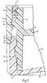
- FIGS 1 to 3 illustrate such a powder inhaler.
- the inhaler comprises a mouthpiece 2 comprising an outlet nozzle 4, an inhaler body 6 and a rotatable grip portion 8 for operating a dosing mechanism for providing doses of powder for inhalation.
- the inhaler body 6 is provided with an opening 10 which is filled with a window 12 through which an indicating wheel (not illustrated) is visible so as to provide an indication as to the usage of the inhaler.
- the inhaler further comprises a cap 14 comprising a tubular section having a closed end which is configured to fit over the mouthpiece 2 and the inhaler body 6.
- the cap 14 includes a sealing surface 15 at the inner peripheral edge of the lip 16 at the open end thereof, which sealing surface 15 tapers outwardly in the direction from the closed to the open end of the cap 14.
- the cap 14 further includes screw threads 17 provided to the inner surface thereof.
- the grip portion 8 comprises first and second hollow parts 18, 20 which are mutually configured so as to define an enclosed chamber 22 for containing desiccant when fitted together.
- the first part 18 comprises a tubular section 24, in this inhaler of generally cylindrical cross-section, having a circumferential ridge 26 disposed about the outer surface of one, the upper, end thereof to which the inhaler body 6 is clipped and screw threads 28 to which the cap 14 having corresponding screw threads 17 is screwed so as to cover the mouthpiece 2 and the inhaler body 6 and thus form a tight seal.
- the first part 18 further comprises an upwardly-directed resiliently-biased arm 30 disposed at the periphery of the upper end thereof, which arm 30, on rotation of the grip portion 8, engages part of the dosing mechanism so as to provide a dose of powder for inhalation.
- the first part 18 yet further comprises a transverse wall 32 which is permeable to moisture.
- the wall 32 is preferably formed at least in part of cardboard.
- the second part 20 comprises a tubular section 34, in this inhaler of senerally cylindrical cross-section, one, the lower, end of which is closed by a wall 36.
- the outer surface of the tubular section 34 includes a plurality of axially-directed ridges 38 which are gripped by a user on rotation of the grip portion 8 and a sealing surface 40 at the outer peripheral edge of the lip 41 at the open end thereof, which sealing surface 40 tapers inwardly in the direction from the closed to the open end of the second part 20.
- the axially-directed ridges 38 could be replaced by a knurled surface.
- the inner dimension of the tubular section 34 is configured so as to be a close radial fit over the tubular section 24 of the first part 18.
- the cap 14 is first removed by unscrewing in one sense. in this inhaler in the counter-clockwise sense when viewed from above.
- the grip portion 8 is then rotated in one sense, in this inhaler also in the counter-clockwise sense when viewed from above, through a predetermined angle relative to the inhaler body 6 and back in the opposite, clockwise, sense to the original position.
- This action operates the dosing mechanism to provide a dose of powder for inhalation.
- the user then takes the mouthpiece 2 in the lips and inhales so as to draw powder into the lungs.
- the cap 14 is then replaced by screwing on in the other, clockwise, sense when viewed from above. In screwing on the cap 14 the sealing surface 15 on the cap 14 is brought into engagement with the sealing surface 40 on the grip portion 8, with a tight seal being achieved by screwing the cap 14 tightly to the grip portion 8.
- the present invention provides an inhaler for administering powder by inhalation, comprising: a housing having a screw thread and a substantially circular sealing surface coaxial therewith: a mouthpiece attached to the housing; and a cap for covering at least the mouthpiece, the cap having a screw thread for engaging the screw thread on the housing and a substantially circular sealing surface for engaging the sealing surface on the housing; wherein the sealing surfaces are shaped and dimensioned such that the radial force therebetween is substantially constant for any relative position where the sealing surfaces engage one another: characterized in that the housing comprises a body and a grip portion which is rotatable relative to the body and on rotation provides a dose of powder for inhalation, in that the screw thread and the sealing surface on the housing are provided on the grip portion and in that the sealing surface on the grip portion is disposed axially forward, in the direction of fitting the cap to the housing, of the screw thread on the grip portion.
- the sealing surface on the grip portion comprises a substantially cylindrical outwardly-facing surface.
- the sealing surface on the cap comprises a substantially cylindrical inwardly-facing surface.
- the sealing surface on the grip portion is provided by a circular lip.
- the sealing surface on the cap is provided by a circular lip.
- the forward end, in the direction of fitting the cap to the housing, of at least one of the lip defining the sealing surface on the grip portion and the lip defining the sealing surface on the cap is shaped so as to guide the sealing surface on the cap onto the sealing surface on the grip portion.
- the respective forward end is rounded.
- the respective forward end is tapered.
- At least one of the lip defining the sealing surface on the grip portion and the lip defining the sealing surface on the cap is resiliently displaceable.
- At least one of the lip defining the sealing surface on the grip portion and the lip defining the sealing surface on the cap is formed of a resilient material.
- the internal diameter of the lip defining the sealing surface on the cap is smaller than the external diameter of the lip defining the sealing surface on the grip portion.
- At least one of the sealing surface on the grip portion and the sealing surface on the cap is a roughened surface.
- the respective sealing surface has a matt surface finish.
- the housing and the cap are both substantially cylindrical and the mouthpiece and the grip portion are disposed at opposite ends of the housing.
- the outer surface of the grip portion has a knurled or ridged surface which can be gripped by a user.
- the grip portion includes a chamber for containing desiccant and at least a part of the grip portion defining the chamber which faces inwardly is permeable to moisture.
- the frictional resistance to rotation of the cap is substantially constant irrespective of how fully the cap is screwed onto the housing.
- a tight seal is achieved irrespective of the area of contact between the sealing surfaces.
- the sealing surfaces are configured such that the force required to screw the cap onto the housing is sufficiently high as to prevent the cap from working loose and falling off, but sufficiently low as to enable a user to screw and unscrew the cap with relative ease.
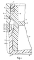
- the powder inhaler in accordance with the preferred embodiment of the present invention is quite similar to the above-described powder inhaler. For this reason. and in order to avoid unnecessary duplication of description, only the structural differences will be described in detail and reference is made to the preceding description.
- This inhaler differs from the above-described powder inhaler principally in that the sealing surface 15 on the cap 14 and the sealing surface 40 on the grip portion 8 comprise axially-extending cylindrical surfaces.
- the sealing surface 15 on the cap 14 is provided by the inner surface of the circumferential lip 16 at the open end thereof and the sealing surface 40 on the grip portion 8 is provided by the outer surface of the circumferential lip 41 at the open end of the tubular section 34 of the second part 20.
- both the sealing surface 15 on the cap 14 and the sealing surface 40 on the grip portion 8 are substantially co-axial, when at rest, the force acting therebetween is principally a radial force.
- essentially the only resistance that will have to be overcome is that due to friction.
- This increase in resistance is, however, relatively insignificant, certainly when compared to the level of resistance encountered in the first-described powder inhaler where the axial force increases significantly as the cap 14 is screwed further onto the grip portion 8.
- the outer peripheral edge 41a of the lip 41 defining the sealing surface 40 on the grip portion 8 is rounded and the inner peripheral edge 16a of the lip 16 defining the sealing surface 15 on the cap 14 is tapered outwardly in the direction from the closed to the open end thereof.
- the sealing surface 15 defined by the lip 16 is guided onto the sealing surface 40 defined by the lip 41.
- the outer peripheral edge 41a of the lip 41 on the grip portion 8 could alternatively be tapered inwardly in the direction from the closed to the open end of the second part 20 thereof and the inner peripheral edge 16a of the lip 16 on the cap 14 could alternatively be rounded.
- the outer peripheral edge 41a of the lip 41 on the grip portion 8 and the inner peripheral edge 16a of the lip 16 on the cap 14 could have any shape which assists in guiding the sealing surface 15 defined by the lip 16 onto the sealing surface 40 defined by the lip 41.
- one or both of the lip 16 defining the sealing surface 15 on the cap 14 and the lip 41 defining the sealing surface 40 on the grip portion 8 are formed from a resilient material.
- one or both or the lip 16 defining the sealing surface 15 on the cap 14 and the lip 41 defining the sealing surface 40 on the grip portion 8 can be formed of a sufficiently small thickness as to be resiliently displaceable.
- one or both of the lip 16 defining the sealing surface 15 on the cap 14 and the lip 41 defining the sealing surface 40 on the grip portion 8 are displaced from the relaxed state so as to provide an increased radial force.
- the increased radial force will contribute to the frictional force which resists loosening of the cap 14.
- the lip 41 on the second part 20 of the grip portion 8 defining the sealing surface 40 is unsupported from behind.
- the lip 41 on the grip portion 8 can be deflected radially inwardly.
- the lip 41 on the grip portion 8 is deflected and acts to provide a sealing force.
- This sealing force is relatively constant throughout the travel of the cap 14 in being screwed onto the grip portion 8. This can be contrasted to the arrangement of the first-described powder inhaler where the lip 41 defining the sealing surface 40 on the grip portion 8 is supported and immovable.
- the first-described powder inhaler relies on compression of the respective lips 16, 41 on the grip portion 8 and the cap 14, neither of which can be made from a particularly resilient material.
- the resistance to screwing on the cap 14 will increase dramatically as the cap 14 is screwed onto the grip portion 8.
- the cap 14 can tend to stick to the sealing surface 40.
- the sealing surface 40 can be formed with or treated to have a slightly roughened finish. It will of course be appreciated that the sealing surface 40 should not be too rough, since a very rough surface would increase the resistance to screwing on the cap 14. In a preferred embodiment the sealing surface 40 has a matt finish.
Claims (16)
- Inhalateur de poudre destiné à administrer de la poudre par inhalation, comprenant :caractérisé en ce que le logement comprend un corps (6) et une portion de saisie (8) qui peut tourner par rapport au corps (6) et qui fournit, lorsqu'elle est tournée, une dose de poudre pour inhalation, en ce que le filet de vis (28) et la surface d'étanchéité (40) sur le logement sont prévus sur la portion de saisie (8) et en ce que la surface d'étanchéité (40) sur la portion de saisie (8) est disposée axialement vers l'avant du filet de vis (28) sur la portion de saisie (8), dans la direction de l'ajustement du capuchon (14) sur le logement.un logement ayant un filet de vis (28) et une surface d'étanchéité substantiellement circulaire (40) coaxiale avec celui-ci ;un embout (2) attaché au logement ; etun capuchon (14) pour recouvrir au moins l'embout (2), le capuchon (14) ayant un filet de vis (17) destiné à s'engager avec le filet de vis (28) sur le logement et une surface d'étanchéité substantiellement circulaire (15) destinée à s'engager avec la surface d'étanchéité (40) sur le logement;les surfaces d'étanchéité (15, 40) étant formées et dimensionnées de telle sorte que la force radiale entre elles soit substantiellement constante pour toute position relative dans laquelle les surfaces d'étanchéité (15, 40) s'engagent l'une avec l'autre ;
- Inhalateur selon la revendication 1, dans lequel la surface d'étanchéité (40) sur la portion de saisie (8) comprend une surface substantiellement cylindrique tournée vers l'extérieur.
- Inhalateur selon la revendication 1 ou 2, dans lequel la surface d'étanchéité (15) sur le capuchon (14) comprend une surface substantiellement cylindrique tournée vers l'intérieur.
- Inhalateur selon l'une quelconque des revendications 1 à 3, dans lequel la surface d'étanchéité (40) sur la portion de saisie (8) est pourvue d'une lèvre circulaire (41).
- Inhalateur selon l'une quelconque des revendications 1 à 4, dans lequel la surface d'étanchéité (15) sur le capuchon (14) est pourvue d'une lèvre circulaire (16).
- Inhalateur selon la revendication 4 ou 5, dans lequel l'extrémité avant, dans la direction d'ajustement du capuchon (14) sur le logement, d'au moins une de la lèvre (41) définissant la surface d'étanchéité (40) sur la portion de saisie (8) et de la lèvre (16) définissant la surface d'étanchéité (15) sur le capuchon (14) est formée de manière à guider la surface d'étanchéité (15) sur le capuchon (14) sur la surface d'étanchéité (40) sur la portion de saisie (8).
- Inhalateur selon la revendication 6, dans lequel l'extrémité avant respective est arrondie.
- Inhalateur selon la revendication 6, dans lequel l'extrémité avant respective est effilée.
- Inhalateur selon l'une quelconque des revendications 4 à 8, dans lequel au moins une de la lèvre (41) définissant la surface d'étanchéité (40) sur la portion de saisie (8) et de la lèvre (16) définissant la surface d'étanchéité (15) sur le capuchon (14) est déplaçable élastiquement.
- Inhalateur selon l'une quelconque des revendications 4 à 9, dans lequel au moins une de la lèvre (41) définissant la surface d'étanchéité (40) sur la portion de saisie (8) et de la lèvre (16) définissant la surface d'étanchéité (15) sur le capuchon (14) est formée d'un matériau élastique.
- Inhalateur selon la revendication 9 ou 10, dans lequel, dans l'état de repos, le diamètre intérieur de la lèvre (16) définissant la surface d'étanchéité (15) sur le capuchon (14) est plus petit que le diamètre extérieur de la lèvre (41) définissant la surface d'étanchéité (40) sur la portion de saisie (8).
- Inhalateur selon l'une quelconque des revendications 1 à 11, dans lequel au moins l'une de la surface d'étanchéité (40) sur la portion de saisie (8) et de la surface d'étanchéité (15) sur le capuchon (14) est une surface rugueuse.
- Inhalateur selon la revendication 12, dans lequel la surface d'étanchéité respective (15, 40) a une finition de surface mate.
- Inhalateur selon l'une quelconque des revendications 1 à 13, dans lequel le logement et le capuchon (14) sont tous deux substantiellement cylindriques et l'embout (2) et la portion de saisie (8) sont disposés à des extrémités opposées du logement.
- Inhalateur selon l'une quelconque des revendications 1 à 14, dans lequel la surface extérieure de la portion de saisie (8) a une surface moletée ou nervurée (38) qui peut être saisie par un utilisateur.
- Inhalateur selon l'une quelconque des revendications 1 à 15, dans lequel la portion de saisie (8) comporte une chambre (22) contenant du dessiccatif et au moins une partie de la portion de saisie (8) définissant la chambre (22) tournée vers l'intérieur est perméable à l'humidité.
Applications Claiming Priority (3)
| Application Number | Priority Date | Filing Date | Title |
|---|---|---|---|
| SE9700948A SE9700948D0 (sv) | 1997-03-14 | 1997-03-14 | Powder inhaler X |
| SE9700948 | 1997-03-14 | ||
| PCT/SE1998/000463 WO1998041262A1 (fr) | 1997-03-14 | 1998-03-13 | Dispositif d'inhalation |
Publications (2)
| Publication Number | Publication Date |
|---|---|
| EP0977607A1 EP0977607A1 (fr) | 2000-02-09 |
| EP0977607B1 true EP0977607B1 (fr) | 2003-08-27 |
Family
ID=20406175
Family Applications (1)
| Application Number | Title | Priority Date | Filing Date |
|---|---|---|---|
| EP98909952A Expired - Lifetime EP0977607B1 (fr) | 1997-03-14 | 1998-03-13 | Dispositif d'inhalation |
Country Status (16)
| Country | Link |
|---|---|
| US (1) | US6446626B1 (fr) |
| EP (1) | EP0977607B1 (fr) |
| JP (1) | JP4189034B2 (fr) |
| AT (1) | ATE247999T1 (fr) |
| AU (1) | AU723932B2 (fr) |
| CA (1) | CA2283194C (fr) |
| DE (1) | DE69817551T2 (fr) |
| DK (1) | DK0977607T3 (fr) |
| ES (1) | ES2205460T3 (fr) |
| HK (1) | HK1025526A1 (fr) |
| NO (1) | NO328770B1 (fr) |
| NZ (1) | NZ337550A (fr) |
| PL (1) | PL187195B1 (fr) |
| PT (1) | PT977607E (fr) |
| SE (1) | SE9700948D0 (fr) |
| WO (1) | WO1998041262A1 (fr) |
Families Citing this family (35)
| Publication number | Priority date | Publication date | Assignee | Title |
|---|---|---|---|---|
| TW469832U (en) * | 1997-03-14 | 2001-12-21 | Astra Ab | Inhalation device |
| US7967011B2 (en) * | 1997-11-14 | 2011-06-28 | Astrazeneca Ab | Inhalation device |
| US9006175B2 (en) | 1999-06-29 | 2015-04-14 | Mannkind Corporation | Potentiation of glucose elimination |
| AU2003220125B2 (en) | 2002-03-20 | 2006-06-15 | Mannkind Corporation | Inhalation apparatus |
| EP1452198A4 (fr) * | 2002-10-11 | 2006-11-02 | Otsuka Pharma Co Ltd | Dispositif d'inhalation de poudre |
| EP3662948B1 (fr) | 2004-03-10 | 2022-11-09 | Glaxo Group Limited | Dispositif de distribution |
| PL1786784T3 (pl) | 2004-08-20 | 2011-04-29 | Mannkind Corp | Kataliza syntezy diketopiperazyn |
| EP2322180B1 (fr) | 2004-08-23 | 2015-05-27 | MannKind Corporation | Sels de diketopiperazine permettant l'administration de médicaments |
| US8210171B2 (en) | 2004-09-13 | 2012-07-03 | Oriel Therapeutics, Inc. | Tubular dry powder drug containment systems, associated inhalers and methods |
| RU2390325C2 (ru) | 2005-09-14 | 2010-05-27 | Маннкайнд Корпорейшн | Способ приготовления лекарственного препарата, основанный на увеличении сродства активных агентов к поверхностям кристаллических микрочастиц |
| RU2403059C2 (ru) | 2006-02-22 | 2010-11-10 | Маннкайнд Корпорейшн | Способ улучшения фармацевтических свойств микрочастиц, содержащих дикетопиперазин и активный агент |
| ES2394589T3 (es) | 2007-12-14 | 2013-02-04 | Aerodesigns, Inc | Suministro de productos alimenticios transformables en aerosol |
| US8485180B2 (en) | 2008-06-13 | 2013-07-16 | Mannkind Corporation | Dry powder drug delivery system |
| US8636001B2 (en) | 2008-06-13 | 2014-01-28 | Mannkind Corporation | Dry powder inhaler and system for drug delivery |
| DK2609954T3 (da) | 2008-06-20 | 2022-02-14 | Mannkind Corp | Interaktivt apparat til realtidsafbildning af inhalationspræstationer |
| TWI614024B (zh) | 2008-08-11 | 2018-02-11 | 曼凱公司 | 超快起作用胰島素之用途 |
| US8314106B2 (en) | 2008-12-29 | 2012-11-20 | Mannkind Corporation | Substituted diketopiperazine analogs for use as drug delivery agents |
| EP2405963B1 (fr) | 2009-03-11 | 2013-11-06 | MannKind Corporation | Appareil, système et procédé de mesure de résistance d'un inhalateur |
| CN102647979B (zh) | 2009-06-12 | 2015-03-04 | 曼金德公司 | 具有确定比表面积的二酮哌嗪颗粒 |
| EP2496295A1 (fr) | 2009-11-03 | 2012-09-12 | MannKind Corporation | Appareil et méthode de simulation d'efforts d'inhalation |
| EP2582421A1 (fr) | 2010-06-21 | 2013-04-24 | MannKind Corporation | Système et procédé d'administration de médicament sous la forme d'une poudre sèche |
| US20120103342A1 (en) * | 2010-11-01 | 2012-05-03 | SHIKANI MEDICAL, LLC d/b/a/ The Airway Company | Multidirectional tracheotomy speaking valve |
| WO2012135765A2 (fr) | 2011-04-01 | 2012-10-04 | Mannkind Corporation | Emballage coque pour cartouches pharmaceutiques |
| WO2012174472A1 (fr) | 2011-06-17 | 2012-12-20 | Mannkind Corporation | Microparticules de dicétopipérazine de capacité élevée |
| CN103945859A (zh) | 2011-10-24 | 2014-07-23 | 曼金德公司 | 用于治疗疼痛的方法和组合物 |
| EP2793984A1 (fr) * | 2011-12-22 | 2014-10-29 | Sanofi SA | Système pour un dispositif d'administration de médicament |
| US9802012B2 (en) | 2012-07-12 | 2017-10-31 | Mannkind Corporation | Dry powder drug delivery system and methods |
| EP2900778B1 (fr) | 2012-09-27 | 2017-05-10 | 3M Innovative Properties Company | Système de distribution |
| US10159644B2 (en) | 2012-10-26 | 2018-12-25 | Mannkind Corporation | Inhalable vaccine compositions and methods |
| SG11201507564PA (en) | 2013-03-15 | 2015-10-29 | Mannkind Corp | Microcrystalline diketopiperazine compositions and methods |
| MX2020009878A (es) | 2013-07-18 | 2022-07-27 | Mannkind Corp | Composiciones farmaceuticas en polvo seco estables al calor y metodos. |
| EP3030294B1 (fr) | 2013-08-05 | 2020-10-07 | MannKind Corporation | Appareil d'insufflation |
| US10307464B2 (en) | 2014-03-28 | 2019-06-04 | Mannkind Corporation | Use of ultrarapid acting insulin |
| US10561806B2 (en) | 2014-10-02 | 2020-02-18 | Mannkind Corporation | Mouthpiece cover for an inhaler |
| GB201702408D0 (en) | 2017-02-14 | 2017-03-29 | Norton (Waterford) Ltd | Inhalers and related methods |
Family Cites Families (12)
| Publication number | Priority date | Publication date | Assignee | Title |
|---|---|---|---|---|
| US443545A (en) * | 1890-12-30 | Device for injecting medical powders | ||
| US2705007A (en) * | 1951-09-10 | 1955-03-29 | Louis P Gerber | Inhaler |
| US2966909A (en) * | 1956-12-14 | 1961-01-03 | A E Halperin Co Inc | Pocket inhalator |
| SE453566B (sv) | 1986-03-07 | 1988-02-15 | Draco Ab | Anordning vid pulverinhalatorer |
| SE466684B (sv) * | 1989-03-07 | 1992-03-23 | Draco Ab | Anordning vid en inhalator samt foerfarande foer att med anordningen registrera medicinering med inhalator |
| US5009323A (en) * | 1989-11-13 | 1991-04-23 | Sunbeam Plastics Corporation | Tamper indicating closure having a rotary seal |
| IT1240750B (it) * | 1990-04-12 | 1993-12-17 | Chiesi Farma Spa | Dispositivo per la somministrazione di sostanze medicamentose in polvere |
| GB2267484B (en) | 1992-04-30 | 1996-10-09 | Beeson & Sons Ltd | Container closure assembly |
| PL173090B1 (pl) * | 1992-12-18 | 1998-01-30 | Schering Corp | Inhalator do sproszkowanych lekarstw |
| US5505195A (en) | 1993-09-16 | 1996-04-09 | Medtrac Technologies Inc. | Dry powder inhalant device with dosage and air flow monitor |
| DE4342251C1 (de) * | 1993-12-10 | 1995-05-11 | Dental Kosmetik Gmbh Dresden | Drehklemmverschluß für Behälter |
| DE4415462C1 (de) | 1994-05-03 | 1995-08-31 | Transcoject Marketing Gmbh | Inhalator |
-
1997
- 1997-03-14 SE SE9700948A patent/SE9700948D0/xx unknown
-
1998
- 1998-03-13 DK DK98909952T patent/DK0977607T3/da active
- 1998-03-13 WO PCT/SE1998/000463 patent/WO1998041262A1/fr active IP Right Grant
- 1998-03-13 AU AU64309/98A patent/AU723932B2/en not_active Ceased
- 1998-03-13 AT AT98909952T patent/ATE247999T1/de active
- 1998-03-13 EP EP98909952A patent/EP0977607B1/fr not_active Expired - Lifetime
- 1998-03-13 US US09/068,388 patent/US6446626B1/en not_active Expired - Lifetime
- 1998-03-13 JP JP54042998A patent/JP4189034B2/ja not_active Expired - Fee Related
- 1998-03-13 ES ES98909952T patent/ES2205460T3/es not_active Expired - Lifetime
- 1998-03-13 PL PL98335819A patent/PL187195B1/pl unknown
- 1998-03-13 DE DE69817551T patent/DE69817551T2/de not_active Expired - Lifetime
- 1998-03-13 NZ NZ337550A patent/NZ337550A/en not_active IP Right Cessation
- 1998-03-13 PT PT98909952T patent/PT977607E/pt unknown
- 1998-03-13 CA CA002283194A patent/CA2283194C/fr not_active Expired - Fee Related
-
1999
- 1999-09-10 NO NO19994384A patent/NO328770B1/no not_active IP Right Cessation
-
2000
- 2000-08-07 HK HK00104914A patent/HK1025526A1/xx not_active IP Right Cessation
Also Published As
| Publication number | Publication date |
|---|---|
| PT977607E (pt) | 2003-12-31 |
| PL335819A1 (en) | 2000-05-22 |
| SE9700948D0 (sv) | 1997-03-14 |
| DE69817551D1 (de) | 2003-10-02 |
| CA2283194C (fr) | 2008-03-18 |
| AU723932B2 (en) | 2000-09-07 |
| ES2205460T3 (es) | 2004-05-01 |
| AU6430998A (en) | 1998-10-12 |
| ATE247999T1 (de) | 2003-09-15 |
| JP4189034B2 (ja) | 2008-12-03 |
| DK0977607T3 (da) | 2003-12-01 |
| WO1998041262A1 (fr) | 1998-09-24 |
| NO328770B1 (no) | 2010-05-10 |
| NZ337550A (en) | 2001-04-27 |
| JP2001516249A (ja) | 2001-09-25 |
| CA2283194A1 (fr) | 1998-09-24 |
| US6446626B1 (en) | 2002-09-10 |
| HK1025526A1 (en) | 2000-11-17 |
| PL187195B1 (pl) | 2004-05-31 |
| NO994384D0 (no) | 1999-09-10 |
| NO994384L (no) | 1999-09-10 |
| DE69817551T2 (de) | 2004-06-17 |
| EP0977607A1 (fr) | 2000-02-09 |
Similar Documents
| Publication | Publication Date | Title |
|---|---|---|
| EP0977607B1 (fr) | Dispositif d'inhalation | |
| JP2001516249A5 (fr) | ||
| EP0977605B1 (fr) | Dispositif d'inhalation | |
| ES2204948T3 (es) | Dispositivo de inhalacion. | |
| AP1259A (en) | Inhalation device with tamperproof closure. | |
| US9895501B2 (en) | Metering device for the inhalation of a pulverulent substance | |
| US6418926B1 (en) | Medicament delivery and packaging | |
| US20090260626A1 (en) | Inhaler for Powdery, Especially Medical Substances | |
| US20070210462A1 (en) | Cap | |
| CA1329526C (fr) | Applicateur de medicament en poudre | |
| SG190716A1 (en) | Inhalers and housing caps for inhalers | |
| US6328032B1 (en) | Inhalation device | |
| AU759730B2 (en) | A tamper resistant closure | |
| AU735126B2 (en) | Inhalation device | |
| MXPA99006248A (en) | Inhalation device |
Legal Events
| Date | Code | Title | Description |
|---|---|---|---|
| PUAI | Public reference made under article 153(3) epc to a published international application that has entered the european phase |
Free format text: ORIGINAL CODE: 0009012 |
|
| 17P | Request for examination filed |
Effective date: 19991014 |
|
| AK | Designated contracting states |
Kind code of ref document: A1 Designated state(s): AT BE CH DE DK ES FI FR GB GR IE IT LI LU MC NL PT SE |
|
| AX | Request for extension of the european patent |
Free format text: LT PAYMENT 19991014;LV PAYMENT 19991014;MK PAYMENT 19991014;RO PAYMENT 19991014;SI PAYMENT 19991014 |
|
| RAP1 | Party data changed (applicant data changed or rights of an application transferred) |
Owner name: ASTRAZENECA AB |
|
| GRAH | Despatch of communication of intention to grant a patent |
Free format text: ORIGINAL CODE: EPIDOS IGRA |
|
| GRAH | Despatch of communication of intention to grant a patent |
Free format text: ORIGINAL CODE: EPIDOS IGRA |
|
| GRAA | (expected) grant |
Free format text: ORIGINAL CODE: 0009210 |
|
| AK | Designated contracting states |
Designated state(s): AT BE CH DE DK ES FI FR GB GR IE IT LI LU MC NL PT SE |
|
| AX | Request for extension of the european patent |
Extension state: LT LV MK RO SI |
|
| REG | Reference to a national code |
Ref country code: GB Ref legal event code: FG4D |
|
| REG | Reference to a national code |
Ref country code: CH Ref legal event code: EP |
|
| REG | Reference to a national code |
Ref country code: IE Ref legal event code: FG4D |
|
| REF | Corresponds to: |
Ref document number: 69817551 Country of ref document: DE Date of ref document: 20031002 Kind code of ref document: P |
|
| REG | Reference to a national code |
Ref country code: DK Ref legal event code: T3 |
|
| REG | Reference to a national code |
Ref country code: SE Ref legal event code: TRGR |
|
| REG | Reference to a national code |
Ref country code: GR Ref legal event code: EP Ref document number: 20030404857 Country of ref document: GR |
|
| LTIE | Lt: invalidation of european patent or patent extension |
Effective date: 20030827 |
|
| REG | Reference to a national code |
Ref country code: ES Ref legal event code: FG2A Ref document number: 2205460 Country of ref document: ES Kind code of ref document: T3 |
|
| ET | Fr: translation filed | ||
| PLBE | No opposition filed within time limit |
Free format text: ORIGINAL CODE: 0009261 |
|
| STAA | Information on the status of an ep patent application or granted ep patent |
Free format text: STATUS: NO OPPOSITION FILED WITHIN TIME LIMIT |
|
| 26N | No opposition filed |
Effective date: 20040528 |
|
| REG | Reference to a national code |
Ref country code: FR Ref legal event code: PLFP Year of fee payment: 19 |
|
| PGFP | Annual fee paid to national office [announced via postgrant information from national office to epo] |
Ref country code: LU Payment date: 20160226 Year of fee payment: 19 |
|
| PGFP | Annual fee paid to national office [announced via postgrant information from national office to epo] |
Ref country code: DE Payment date: 20160308 Year of fee payment: 19 Ref country code: MC Payment date: 20160126 Year of fee payment: 19 Ref country code: IE Payment date: 20160309 Year of fee payment: 19 Ref country code: NL Payment date: 20160310 Year of fee payment: 19 Ref country code: CH Payment date: 20160311 Year of fee payment: 19 Ref country code: DK Payment date: 20160310 Year of fee payment: 19 Ref country code: ES Payment date: 20160211 Year of fee payment: 19 |
|
| PGFP | Annual fee paid to national office [announced via postgrant information from national office to epo] |
Ref country code: GB Payment date: 20160309 Year of fee payment: 19 Ref country code: FI Payment date: 20160309 Year of fee payment: 19 Ref country code: PT Payment date: 20160315 Year of fee payment: 19 Ref country code: GR Payment date: 20160212 Year of fee payment: 19 Ref country code: FR Payment date: 20160208 Year of fee payment: 19 Ref country code: SE Payment date: 20160311 Year of fee payment: 19 Ref country code: BE Payment date: 20151223 Year of fee payment: 19 Ref country code: AT Payment date: 20160225 Year of fee payment: 19 |
|
| PGFP | Annual fee paid to national office [announced via postgrant information from national office to epo] |
Ref country code: IT Payment date: 20160324 Year of fee payment: 19 |
|
| REG | Reference to a national code |
Ref country code: DE Ref legal event code: R119 Ref document number: 69817551 Country of ref document: DE |
|
| REG | Reference to a national code |
Ref country code: DK Ref legal event code: EBP Effective date: 20170331 |
|
| PG25 | Lapsed in a contracting state [announced via postgrant information from national office to epo] |
Ref country code: FI Free format text: LAPSE BECAUSE OF NON-PAYMENT OF DUE FEES Effective date: 20170313 |
|
| REG | Reference to a national code |
Ref country code: CH Ref legal event code: PL Ref country code: SE Ref legal event code: EUG |
|
| REG | Reference to a national code |
Ref country code: NL Ref legal event code: MM Effective date: 20170401 |
|
| REG | Reference to a national code |
Ref country code: AT Ref legal event code: MM01 Ref document number: 247999 Country of ref document: AT Kind code of ref document: T Effective date: 20170313 |
|
| GBPC | Gb: european patent ceased through non-payment of renewal fee |
Effective date: 20170313 |
|
| PG25 | Lapsed in a contracting state [announced via postgrant information from national office to epo] |
Ref country code: PT Free format text: LAPSE BECAUSE OF NON-PAYMENT OF DUE FEES Effective date: 20170913 Ref country code: MC Free format text: LAPSE BECAUSE OF NON-PAYMENT OF DUE FEES Effective date: 20170331 Ref country code: SE Free format text: LAPSE BECAUSE OF NON-PAYMENT OF DUE FEES Effective date: 20170314 |
|
| REG | Reference to a national code |
Ref country code: IE Ref legal event code: MM4A |
|
| REG | Reference to a national code |
Ref country code: FR Ref legal event code: ST Effective date: 20171130 |
|
| PG25 | Lapsed in a contracting state [announced via postgrant information from national office to epo] |
Ref country code: FR Free format text: LAPSE BECAUSE OF NON-PAYMENT OF DUE FEES Effective date: 20170331 Ref country code: LU Free format text: LAPSE BECAUSE OF NON-PAYMENT OF DUE FEES Effective date: 20170313 Ref country code: DE Free format text: LAPSE BECAUSE OF NON-PAYMENT OF DUE FEES Effective date: 20171003 Ref country code: AT Free format text: LAPSE BECAUSE OF NON-PAYMENT OF DUE FEES Effective date: 20170313 Ref country code: NL Free format text: LAPSE BECAUSE OF NON-PAYMENT OF DUE FEES Effective date: 20170401 |
|
| PG25 | Lapsed in a contracting state [announced via postgrant information from national office to epo] |
Ref country code: LI Free format text: LAPSE BECAUSE OF NON-PAYMENT OF DUE FEES Effective date: 20170331 Ref country code: GB Free format text: LAPSE BECAUSE OF NON-PAYMENT OF DUE FEES Effective date: 20170313 Ref country code: IT Free format text: LAPSE BECAUSE OF NON-PAYMENT OF DUE FEES Effective date: 20170313 Ref country code: IE Free format text: LAPSE BECAUSE OF NON-PAYMENT OF DUE FEES Effective date: 20170313 Ref country code: CH Free format text: LAPSE BECAUSE OF NON-PAYMENT OF DUE FEES Effective date: 20170331 Ref country code: GR Free format text: LAPSE BECAUSE OF NON-PAYMENT OF DUE FEES Effective date: 20171005 |
|
| REG | Reference to a national code |
Ref country code: BE Ref legal event code: MM Effective date: 20170331 |
|
| PG25 | Lapsed in a contracting state [announced via postgrant information from national office to epo] |
Ref country code: DK Free format text: LAPSE BECAUSE OF NON-PAYMENT OF DUE FEES Effective date: 20170331 |
|
| REG | Reference to a national code |
Ref country code: ES Ref legal event code: FD2A Effective date: 20180507 |
|
| PG25 | Lapsed in a contracting state [announced via postgrant information from national office to epo] |
Ref country code: PT Free format text: LAPSE BECAUSE OF EXPIRATION OF PROTECTION Effective date: 20180321 Ref country code: BE Free format text: LAPSE BECAUSE OF NON-PAYMENT OF DUE FEES Effective date: 20170331 |
|
| PG25 | Lapsed in a contracting state [announced via postgrant information from national office to epo] |
Ref country code: ES Free format text: LAPSE BECAUSE OF NON-PAYMENT OF DUE FEES Effective date: 20170314 |