EP0974862B1 - Apparatus for swinging an optical device, carrier with such an apparatus for a camera, and large format camera with such a carrier - Google Patents
Apparatus for swinging an optical device, carrier with such an apparatus for a camera, and large format camera with such a carrier Download PDFInfo
- Publication number
- EP0974862B1 EP0974862B1 EP19980113118 EP98113118A EP0974862B1 EP 0974862 B1 EP0974862 B1 EP 0974862B1 EP 19980113118 EP19980113118 EP 19980113118 EP 98113118 A EP98113118 A EP 98113118A EP 0974862 B1 EP0974862 B1 EP 0974862B1
- Authority
- EP
- European Patent Office
- Prior art keywords
- carrier
- arrangement
- accordance
- further characterised
- camera
- Prior art date
- Legal status (The legal status is an assumption and is not a legal conclusion. Google has not performed a legal analysis and makes no representation as to the accuracy of the status listed.)
- Expired - Lifetime
Links
Images
Classifications
-
- G—PHYSICS
- G03—PHOTOGRAPHY; CINEMATOGRAPHY; ANALOGOUS TECHNIQUES USING WAVES OTHER THAN OPTICAL WAVES; ELECTROGRAPHY; HOLOGRAPHY
- G03B—APPARATUS OR ARRANGEMENTS FOR TAKING PHOTOGRAPHS OR FOR PROJECTING OR VIEWING THEM; APPARATUS OR ARRANGEMENTS EMPLOYING ANALOGOUS TECHNIQUES USING WAVES OTHER THAN OPTICAL WAVES; ACCESSORIES THEREFOR
- G03B5/00—Adjustment of optical system relative to image or object surface other than for focusing
- G03B5/08—Swing backs
-
- G—PHYSICS
- G03—PHOTOGRAPHY; CINEMATOGRAPHY; ANALOGOUS TECHNIQUES USING WAVES OTHER THAN OPTICAL WAVES; ELECTROGRAPHY; HOLOGRAPHY
- G03B—APPARATUS OR ARRANGEMENTS FOR TAKING PHOTOGRAPHS OR FOR PROJECTING OR VIEWING THEM; APPARATUS OR ARRANGEMENTS EMPLOYING ANALOGOUS TECHNIQUES USING WAVES OTHER THAN OPTICAL WAVES; ACCESSORIES THEREFOR
- G03B19/00—Cameras
- G03B19/02—Still-picture cameras
- G03B19/10—Plate or cut-film cameras
-
- G—PHYSICS
- G03—PHOTOGRAPHY; CINEMATOGRAPHY; ANALOGOUS TECHNIQUES USING WAVES OTHER THAN OPTICAL WAVES; ELECTROGRAPHY; HOLOGRAPHY
- G03B—APPARATUS OR ARRANGEMENTS FOR TAKING PHOTOGRAPHS OR FOR PROJECTING OR VIEWING THEM; APPARATUS OR ARRANGEMENTS EMPLOYING ANALOGOUS TECHNIQUES USING WAVES OTHER THAN OPTICAL WAVES; ACCESSORIES THEREFOR
- G03B5/00—Adjustment of optical system relative to image or object surface other than for focusing
- G03B5/06—Swinging lens about normal to the optical axis
Definitions
- the invention relates to an arrangement for pivoting a optical device according to the preamble of the claim 1.
- the invention further relates to a carrier for a Camera with such an arrangement and a specialist camera with such a carrier.
- the view camera contains one Arrangement, which essentially consists of a support, a Segment and a cross slide. To the frame the support is attached, which is the vertical one Swivel axis determined. Support is in the segment with With the help of a pivot bearing with balls and is on a cross slide movably supported in one Swivel member slidably mounted and by means of a Clamping device can be locked. In the cross slide raceways are provided for balls that run lengthways Circular arc concentric around the horizontal swivel axis run. The balls roll on these tracks from, so that the lowest possible frictional forces are overcome. For swiveling the picture frame around the a mechanism is provided for the horizontal pivot axis.
- plain bearings can be made from low-friction Material can be provided.
- the invention has for its object an arrangement to improve the pivoting of an optical device.
- a carrier for one around a horizontal and vertical With pivoting lens frame or picture frame with an arrangement is according to the invention by the features of claim 5 characterized.
- This carrier has the advantages that the arrangement, which determines the horizontal pivot axis above the Device is arranged, which is the vertical Determines pivot axis so that the lens frame or the picture frame when swiveling around the two axes does not make any staggering and that by the Elimination of the mechanism for pivoting the height and the weight is reduced.
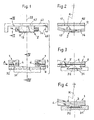
- FIGS. 1 to 4. This one The arrangement in question consists of Essentially of two management units 1, a swivel part 2 and three set screws 6.
- Each guide unit 1 has an elongated body 3 with a flat surface for fixing it and one arcuate surface.
- the body 3 is on one Long side with a circular arc with a radius R trained groove 4, the two to the pivot axis Form concentric storage areas and the other Provide a straight slot 5 on the long side.
- the Set screws 6 are in the area of the slot 5 and across screwed into the body 3.
- the swivel part 2 has an elongated central part 11 with a flat surface 12 for fastening the same and with an arcuate surface 13 and two as Circular arc with the radius R formed sliding sections 14 on, the two concentric to the pivot axis Form storage areas and protrude on the long sides.
- the guide units 1 are spaced apart arranged a support member 31 and the pivot member 2 arranged between the guide units so that the Engage sliding sections 14 in the grooves 4.
- the Set screws 6 is the width of the grooves 4 so adjustable that the game between the concentric Bearing surfaces of the groove 4 and the sliding section 14 canceled and a self-locking swivel movement is achieved.
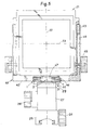
- FIG. 5 shows a carrier with a picture frame 21, the about a vertical axis 22 and about a horizontal axis 23 is pivotable and with that described above Arrangement.
- the carrier does not contain shown camera base a sliding head 25 with a Locking device 26 to the picture frame Move or set the camera base, one Device 27 with a locking device 28, which determines the vertical pivot axis 22 and which on the Sliding head 25 is attached, a guide 29 which on the device 27 determining the vertical pivot axis is detachably arranged and the one in question Arrangement which the horizontal pivot axis 23rd determined and which in the guide 29 parallel to horizontal axis 23 is slidably disposed.
- the guide is a dovetail guide with one stationary guide part 31, which on the device 27 is fixed and with a movable guide part 32, which is designed as a carrier for the arrangement and on which the guide units 1 are attached.
- the picture frame 21 is in a fork-shaped holder 41 with a base section 42 and two legs 43 slidably arranged.
- the legs 43 are Elongated holes 44 formed.
- the base section 32 is a groove 46 for receiving the arrangement educated. The arrangement is via the swivel part 2 attached to the holder 41 by means of screws 47.
- the arrangement comprises guide units 1 with a arcuate groove 4 with a swivel part 2 arcuate skids 14 and means 6 for adjustment the width of the groove. This can advantageously a self-locking swing with simple means be achieved.
- a support for a lens or picture frame with this arrangement has the advantages of eliminating one Adjustment device for horizontal swiveling and the associated savings in weight and height a view camera and a wobble-free swivel of the Lens and picture frame.
Landscapes
- Physics & Mathematics (AREA)
- General Physics & Mathematics (AREA)
- Accessories Of Cameras (AREA)
Description
Die Erfindung betrifft eine Anordnung zum Schwenken eines
optischen Gerätes gemäss dem Oberbegriff des Anspruches
1. Die Erfindung betrifft ferner einen Träger für eine
Kamera mit einer solchen Anordnung sowie eine Fachkamera mit
einem solchen Träger.The invention relates to an arrangement for pivoting a
optical device according to the preamble of the
In der DE-17 72 918 ist eine Fachkamera mit einem Bildrahmen und einem Objektivrahmen beschrieben, die um eine horizontale und eine vertikale Achse geschwenkt werden können. Hierzu enthält die Fachkamera eine Anordnung, die im Wesentlichen aus einen Support, einem Segment und einem Querschlitten besteht. An den Rahmen ist jeweils der Support befestigt, welcher die vertikale Schwenkachse bestimmt. Der Support ist im Segment mit Hilfe eines Drehlagers mit Kugeln gelagert und ist auf einem Querschlitten bewegbar abgestützt, der in einem Schwenkglied verschiebbar gelagert und mittels einer Klemmvorrichtung arretiert werden kann. Im Querschlitten sind Laufbahnen für Kugeln vorgesehen, die längs Kreisbogen konzentrisch um die horizontale Schwenkachse verlaufen. Die Kugeln wälzen sich auf diesen Laufbahnen ab, so dass möglichst geringe Reibungskräfte zu überwinden sind. Zur Schwenkung des Bildrahmens um die horizontale Schwenkachse ist ein Mechanismus vorgesehen. In DE-17 72 918 is a specialist camera with a Picture frame and a lens frame described that around a horizontal and a vertical axis pivoted can be. For this purpose, the view camera contains one Arrangement, which essentially consists of a support, a Segment and a cross slide. To the frame the support is attached, which is the vertical one Swivel axis determined. Support is in the segment with With the help of a pivot bearing with balls and is on a cross slide movably supported in one Swivel member slidably mounted and by means of a Clamping device can be locked. In the cross slide raceways are provided for balls that run lengthways Circular arc concentric around the horizontal swivel axis run. The balls roll on these tracks from, so that the lowest possible frictional forces are overcome. For swiveling the picture frame around the a mechanism is provided for the horizontal pivot axis.
Anstelle der Kugeln können Gleitlager aus reibungsarmen Material vorgesehen werden.Instead of the balls, plain bearings can be made from low-friction Material can be provided.
Der Nachteil dieser Anordnung ist im Wesentlichen darin zu sehen, dass ein Mechanismus zur Schwenkung um die Achse und/oder eine Einrichtung zum Festlegen der Stellung vorgesehen ist.The disadvantage of this arrangement is essentially in it to see a mechanism for pivoting around the Axis and / or a device for setting the Position is provided.
Der Erfindung liegt die Aufgabe zugrunde eine Anordnung zum Schwenken eines optischen Gerätes zu verbessern.The invention has for its object an arrangement to improve the pivoting of an optical device.
Diese Aufgabe wird erfindungsgemäss mit den
kennzeichnenden Merkmalen des Anspruches 1 gelöst.This object is achieved with the
characterizing features of
Die mit der Erfindung erreichbaren Vorteile sind darin zu sehen, dass die Anordnung einfach aufgebaut, der Raumbedarf gering und wartungsfrei ist und keine Feststelleinrichtung benötigt.The advantages achievable with the invention are there too see that the arrangement is simple, the Space requirements are low and maintenance-free and none Locking device needed.
Ein Träger für einen um eine horizontale und vertikale
Achse schwenkbaren Objektivrahmen oder Bildrahmen mit
einer Anordnung ist erfindungsgemäss durch die Merkmale
des Anspruches 5 gekennzeichnet.A carrier for one around a horizontal and vertical
With pivoting lens frame or picture frame with
an arrangement is according to the invention by the features
of
Dieser Träger hat die Vorteile, dass die Anordnung, welche die horizontale Schwenkachse bestimmt oberhalb der Einrichtung angeordnet ist, welche die vertikale Schwenkachse bestimmt, so dass der Objektivrahmen bzw. der Bildrahmen bei der Schwenkung um die beiden Achse keinerlei Torkelbewegung ausführt und dass durch den Wegfall des Mechanismus zur Schwenkung die Bauhöhe und das Gewicht verringert wird.This carrier has the advantages that the arrangement, which determines the horizontal pivot axis above the Device is arranged, which is the vertical Determines pivot axis so that the lens frame or the picture frame when swiveling around the two axes does not make any staggering and that by the Elimination of the mechanism for pivoting the height and the weight is reduced.
Nachfolgend werden Ausführungen der Erfindung anhand der beiliegenden Zeichnungen erläutert. Embodiments of the invention are described below with reference to the accompanying Drawings explained.
Es zeigen:
- Fig.1
- Eine Ansicht einer Ausführung einer erfindungsgemässen Anordnung in auseinander gezogener Darstellung;
- Fig.2
- einen Schnitt entlang der Linie II-II in Fig.1;
- Fig.3
- eine Ansicht in Richtung des Pfeiles A in Fig.1;
- Fig.4
- einen Schnitt entlang der Linie IV-IV in Fig.1 und
- Fig.5
- eine Ausführung eines erfindungsgemässen Trägers mit einem Bildrahmen;
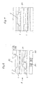
- Fig.6
- eine andere Ausführung eines erfindungsgemässen Träger und
- Fig.7
- eine Ansicht in Richtung des Pfeiles A in Fig.6.
- Fig. 1
- A view of an embodiment of an arrangement according to the invention in an exploded view;
- Fig. 2
- a section along the line II-II in Fig.1;
- Fig. 3
- a view in the direction of arrow A in Fig.1;
- Fig. 4
- a section along the line IV-IV in Fig.1 and
- Fig. 5
- an embodiment of a carrier according to the invention with a picture frame;
- Fig. 6
- another embodiment of a carrier according to the invention and
- Fig. 7
- a view in the direction of arrow A in Fig.6.
Es wird auf die Figuren 1 bis 4 Bezug genommen. Die hier
in Rede stehende Anordnung besteht im
Wesentlichen aus zwei Führungseinheiten 1,
einem Schwenkteil 2 und drei Stellschrauben 6.Reference is made to FIGS. 1 to 4. This one
The arrangement in question consists of
Essentially of two
Jede Führungseinheit 1 hat einen länglichen Körper 3 mit
einer ebenen Fläche zum Befestigen desselben und einer
bogenförmigen Fläche. Der Körper 3 ist an einer
Längsseite mit einer als Kreisbogen mit einem Radius R
ausgebildeten Nut 4, die zwei zur Schwenkachse
konzentrisch Lagerflächen bilden und an der anderen
Längsseite mit einem geraden Schlitz 5 versehen. Die
Stellschrauben 6 sind im Bereich des Schlitzes 5 und quer
zu diesen in den Körper 3 eingeschraubt.Each
Der Schwenkteil 2 weist einen länglichen Mittelteil 11
mit einer ebenen Fläche 12 zum Befestigen desselben und
mit einer bogenförmigen Fläche 13 sowie zwei als
Kreisbogen mit dem Radius R ausgebildete Gleitabschnitte
14 auf, die zwei zur Schwenkachse konzentrisch
Lagerflächen bilden und an den Längsseiten abstehen.The
Die Führungseinheiten 1 sind im Abstand zueinander an
einem Tragteil 31 angeordnet und der Schwenkteil 2 ist
zwischen den Führungseinheiten so angeordnet, dass die
Gleitabschnitte 14 in die Nuten 4 eingreifen. Mittels der
Stellschrauben 6 ist die Weite der Nuten 4 so
einstellbar, dass das Spiel zwischen den konzentrischen
Lagerflächen der Nut 4 und des Gleitabschnittes 14
aufgehoben und eine selbsthemmende Schwenkbewegung
erzielt wird.The
Die Fig.5 zeigt einen Träger mit einem Bildrahmen 21, der
um eine vertikale Achse 22 und um eine horizontale Achse
23 schwenkbar ist und mit der vorstehend beschriebenen
Anordnung.5 shows a carrier with a
Der Träger enthält ausgehend von einer nicht
dargestellten Kamerabasis einen Schiebekopf 25 mit einer
Feststelleinrichtung 26, um den Bildrahmen auf
Kamerabasis verschieben bzw. festzulegen, eine
Einrichtung 27 mit einer Feststelleinrichtung 28, welche
die vertikale Schwenkachse 22 bestimmt und welche auf dem
Schiebekopf 25 befestigt ist, eine Führung 29, welche auf
der die vertikale Schwenkachse bestimmende Einrichtung 27
lösbar angeordnet ist und die hier in Rede stehende
Anordnung, welche die horizontale Schwenkachse 23
bestimmt und welche in der Führung 29 parallel zur
horizontalen Achse 23 verschiebbar angeordnet ist.Starting from one, the carrier does not contain
shown camera base a sliding
Die Führung ist eine Schwalbenschwanzführung mit einem
ortsfesten Führungsteil 31, der an der Einrichtung 27
befestigt ist und mit einem beweglichen Führungsteil 32,
der als Träger für die Anordnung ausgebildet ist und an
welchem die Führungseinheiten 1 befestigt sind.The guide is a dovetail guide with one
Der Bildrahmen 21 ist in einem gabelförmigen Halter 41
mit einem Basisabschnitt 42 und zwei Schenkeln 43
verschiebbar angeordnet. In den Schenkeln 43 sind
Langlöcher 44 ausgebildet. Es sind Feststellmittel 45
vorgesehen, welche die Langlöcher durchgreifen, um den
Bildrahmen 21 am Halter 41 festzulegen. Im Basisabschnitt
32 ist eine Auskehlung 46 zur Aufnahme der Anordnung
ausgebildet. Die Anordnung ist über den Schwenkteil 2
mittels Schrauben 47 am Halter 41 befestigt.The
Bei dem in den Figuren 6 und 7 dargestellten Träger sind
zwei Anordnungen vorgesehen, die aufeinander liegend so
montiert sind, dass die Schwenkachsen sich rechtwinklig
kreuzen. Zwischen den Anordnungen sind Verbindungsorgane
51 vorgesehen, die mit den Führungseinheiten 1 mittels
nicht dargestellten Schrauben verbunden sind. Zum Halten
eines optischen Gerätes ist eine entsprechende
Einrichtung 52 vorgesehen. Zur Befestigung des Trägers an
einem Stativ ist ein Basisteil 53 mit einer Gewindebuchse
54 vorgesehen. Es wird darauf hingewiesen, dass mit
dieser Ausführung die Schwenkachsen unter beliebigen
Winkeln vorgesehen werden können.In the carrier shown in Figures 6 and 7 are
two arrangements are provided, lying one on top of the other
are mounted so that the swivel axes are at right angles
cross. There are links between the
Die Anordnung umfasst Führungseinheiten 1 mit einer
bogenförmigen Nut 4, einen Schwenkteil 2 mit
bogenförmigen Gleitkufen 14 und Mittel 6 zum Einstellen
der Weite der Nut. Dadurch kann in vorteilhafter Weise
eine selbshemmende Schwenkung mit einfachen Mitteln
erzielt werden.The arrangement comprises
Ein Träger für einen Objektiv- oder einen Bildrahmen mit dieser Anordnung hat die Vorteile des Wegfalls einer Einstelleinrichtung für die horizontale Schwenkung und der damit verbundenen Einsparung an Gewicht und Höhe bei einer Fachkamera sowie einer torkelfreien Schwenkung des Objektiv- und Bildrahmens.A support for a lens or picture frame with this arrangement has the advantages of eliminating one Adjustment device for horizontal swiveling and the associated savings in weight and height a view camera and a wobble-free swivel of the Lens and picture frame.
Claims (9)
- Arrangement for the pivoting of an optical apparatus about an axis, said arrangement having a guide unit (1) with an arcuate groove (4) and a pivotable part (2) having an arcuate slide section (14) which is displaceable along the groove relative to the guide unit, characterised by means (6) for the adjustment of the width of the groove (4) in order to achieve a self-locking pivoting.
- Arrangement in accordance with claim 1, further characterised in that the guide unit (1) has an elongate body which is provided with the groove (4) at one longitudinal side and is provided with a slot (5) at the other longitudinal side and in that the means (6) includes at least one adjustment screw which passes through the slot in order to set the width of the groove (4) by changing the width of the slot (5).
- Arrangement in accordance with claim 1 or claim 2, further characterised in that two guide units (1) are provided which are secured at a spacing from one another on a carrier part (31) and in that the pivotable part (2) is formed as an elongate body with two slide sections (14) which project at opposite sides of the body and are in engagement with the grooves (4) of the guide units (1).
- Carrier for an optical apparatus having two arrangements in accordance with one of the claims 1 to 3, further characterised in that the arrangements are arranged such that the pivot axes cross.
- Carrier for an objective frame of a camera or an image frame of a camera, comprising a holder (41) for the objective frame or the image frame, comprising a means (27) in order to pivot the objective frame or image frame respectively about a vertical axis (22) and comprising an arrangement in accordance with one of the claims 1 to 3, further characterised in that the arrangement is arranged above the means (27) for the vertical pivot axis in order to pivot the objective frame or image frame respectively about a horizontal axis (23).
- Carrier in accordance with claim 5, further characterised in that the arrangement for the horizontal pivot axis (23) is arranged at least partly in the holder (41) for the objective frame or the image frame.
- Carrier in accordance with claim 5, further characterised in that the holder (41) is provided with a base section (42) and two limbs (43) for the adjustable reception of the objective frame or the image frame and with means (45) for the fixation of the objective frame or the image frame.
- Carrier in accordance with claim 5, further characterised in that the holder (41) has a recess (46), the centre line of which intersects the vertical axis (22) and extends transversely to the horizontal axis (22) and in that the guide unit (1) or the pivotable part (2) are arranged in the recess.
- Plate or technical camera having a carrier in accordance with one of the claims 5 to 8.
Priority Applications (1)
| Application Number | Priority Date | Filing Date | Title |
|---|---|---|---|
| EP19980113118 EP0974862B1 (en) | 1998-07-15 | 1998-07-15 | Apparatus for swinging an optical device, carrier with such an apparatus for a camera, and large format camera with such a carrier |
Applications Claiming Priority (1)
| Application Number | Priority Date | Filing Date | Title |
|---|---|---|---|
| EP19980113118 EP0974862B1 (en) | 1998-07-15 | 1998-07-15 | Apparatus for swinging an optical device, carrier with such an apparatus for a camera, and large format camera with such a carrier |
Publications (2)
| Publication Number | Publication Date |
|---|---|
| EP0974862A1 EP0974862A1 (en) | 2000-01-26 |
| EP0974862B1 true EP0974862B1 (en) | 2001-10-17 |
Family
ID=8232270
Family Applications (1)
| Application Number | Title | Priority Date | Filing Date |
|---|---|---|---|
| EP19980113118 Expired - Lifetime EP0974862B1 (en) | 1998-07-15 | 1998-07-15 | Apparatus for swinging an optical device, carrier with such an apparatus for a camera, and large format camera with such a carrier |
Country Status (1)
| Country | Link |
|---|---|
| EP (1) | EP0974862B1 (en) |
Cited By (1)
| Publication number | Priority date | Publication date | Assignee | Title |
|---|---|---|---|---|
| DE102010036405A1 (en) | 2010-07-14 | 2012-01-19 | Philippe Vogt | tripod head |
Families Citing this family (2)
| Publication number | Priority date | Publication date | Assignee | Title |
|---|---|---|---|---|
| EP1671180B1 (en) | 2003-10-07 | 2008-08-27 | Lensbabies, Llc. | Flexible lens mount system for rapid tilt photography |
| US8075201B2 (en) | 2006-08-30 | 2011-12-13 | Lensbaby, Llc | Movable lens systems and associated methods |
Family Cites Families (2)
| Publication number | Priority date | Publication date | Assignee | Title |
|---|---|---|---|---|
| CH457131A (en) * | 1967-09-06 | 1968-05-31 | Koch Carl | Photographic focusing screen camera |
| US4814803A (en) * | 1987-08-07 | 1989-03-21 | Wisner Ronald B J | Mid-line tilt mechanism for view camera |
-
1998
- 1998-07-15 EP EP19980113118 patent/EP0974862B1/en not_active Expired - Lifetime
Cited By (2)
| Publication number | Priority date | Publication date | Assignee | Title |
|---|---|---|---|---|
| DE102010036405A1 (en) | 2010-07-14 | 2012-01-19 | Philippe Vogt | tripod head |
| WO2012007244A1 (en) | 2010-07-14 | 2012-01-19 | Philippe Vogt | Tripod head |
Also Published As
| Publication number | Publication date |
|---|---|
| EP0974862A1 (en) | 2000-01-26 |
Similar Documents
| Publication | Publication Date | Title |
|---|---|---|
| DE2913186C2 (en) | Tiltable roller bearing | |
| DE69724888T2 (en) | Shoe binding device for a gliding board | |
| DE69411251T2 (en) | Slider with adjustable track positioning | |
| AT402092B (en) | LINEAR GUIDE | |
| EP0974862B1 (en) | Apparatus for swinging an optical device, carrier with such an apparatus for a camera, and large format camera with such a carrier | |
| DE2550743C2 (en) | Positioning device controlled by a threaded spindle | |
| DE2735073A1 (en) | DEVICE FOR THE PROCESSING OF A WORKPIECE USING A MILLING MACHINE | |
| DE3141158C2 (en) | Guide device for a retractable and retractable insert in the body of a cabinet | |
| DE9315178U1 (en) | Linear guide | |
| DE4310501C1 (en) | Device for controlled greasing of band-shaped workpieces - has bearing blocks, held on base plates via bearing pin | |
| AT504107B1 (en) | CONTACT WIRE SIDE HOLDER | |
| DE69224756T2 (en) | ARM AND HAND SUPPORT FOR A USER OF A KEYBOARD, CHARACTER, KNITTING INSTRUMENT OR DEVICE | |
| DE60106886T2 (en) | SMALL TABLE WITH HEIGHT ADJUSTABLE TABLE TOP | |
| DE3541256A1 (en) | PANTOGRAPH | |
| WO1988004972A1 (en) | Device for moving parts or objects in a straight line | |
| DE2543564A1 (en) | Displaceable table esp. for measuring appts. - has platform tiltable on ring linearly movable on base | |
| DE4447345C1 (en) | Infinitely adjustable support for workpieces in machine tools | |
| DE10325073A1 (en) | Drill framework for drilling machine used in carpentry, connects drilling machine to setting structure using single guide post, in which displaceable drilling machine holder is pivoted on guide post | |
| AT406841B (en) | DRESSING PLANER | |
| DE3329151A1 (en) | Linear guideway | |
| DE10125381A1 (en) | Bearing block for connecting slide which moves along rail with component to be transported comprises upper and lower sections connected by rod which fits into transverse bore with diverging ends | |
| DE3044612A1 (en) | Slide guide with screwed spindle - has spindle at side and roller bearings between inclined faces | |
| DE19823259A1 (en) | Adjustment device for incline of tabletops and other plates | |
| DE4425092C1 (en) | Tool closure system for injection moulding machine carrying heavy, large tools | |
| DE2253290C3 (en) | Device for guiding a cutting torch |
Legal Events
| Date | Code | Title | Description |
|---|---|---|---|
| PUAI | Public reference made under article 153(3) epc to a published international application that has entered the european phase |
Free format text: ORIGINAL CODE: 0009012 |
|
| AK | Designated contracting states |
Kind code of ref document: A1 Designated state(s): CH FR GB LI |
|
| AX | Request for extension of the european patent |
Free format text: AL;LT;LV;MK;RO;SI |
|
| 17P | Request for examination filed |
Effective date: 20000504 |
|
| 17Q | First examination report despatched |
Effective date: 20000705 |
|
| AKX | Designation fees paid |
Free format text: CH FR GB LI |
|
| GRAG | Despatch of communication of intention to grant |
Free format text: ORIGINAL CODE: EPIDOS AGRA |
|
| RTI1 | Title (correction) |
Free format text: APPARATUS FOR SWINGING AN OPTICAL DEVICE, CARRIER WITH SUCH AN APPARATUS FOR A CAMERA, AND LARGE FORMAT CAMERA WITH SUCH A CARRIER |
|
| REG | Reference to a national code |
Ref country code: DE Ref legal event code: 8566 |
|
| GRAG | Despatch of communication of intention to grant |
Free format text: ORIGINAL CODE: EPIDOS AGRA |
|
| GRAH | Despatch of communication of intention to grant a patent |
Free format text: ORIGINAL CODE: EPIDOS IGRA |
|
| GRAH | Despatch of communication of intention to grant a patent |
Free format text: ORIGINAL CODE: EPIDOS IGRA |
|
| GRAA | (expected) grant |
Free format text: ORIGINAL CODE: 0009210 |
|
| AK | Designated contracting states |
Kind code of ref document: B1 Designated state(s): CH FR GB LI |
|
| REG | Reference to a national code |
Ref country code: CH Ref legal event code: EP |
|
| GBT | Gb: translation of ep patent filed (gb section 77(6)(a)/1977) |
Effective date: 20011017 |
|
| REG | Reference to a national code |
Ref country code: GB Ref legal event code: IF02 |
|
| ET | Fr: translation filed | ||
| PGFP | Annual fee paid to national office [announced via postgrant information from national office to epo] |
Ref country code: GB Payment date: 20020822 Year of fee payment: 5 |
|
| PLBE | No opposition filed within time limit |
Free format text: ORIGINAL CODE: 0009261 |
|
| STAA | Information on the status of an ep patent application or granted ep patent |
Free format text: STATUS: NO OPPOSITION FILED WITHIN TIME LIMIT |
|
| 26N | No opposition filed | ||
| PG25 | Lapsed in a contracting state [announced via postgrant information from national office to epo] |
Ref country code: GB Free format text: LAPSE BECAUSE OF NON-PAYMENT OF DUE FEES Effective date: 20030715 |
|
| GBPC | Gb: european patent ceased through non-payment of renewal fee |
Effective date: 20030715 |
|
| PGFP | Annual fee paid to national office [announced via postgrant information from national office to epo] |
Ref country code: CH Payment date: 20091030 Year of fee payment: 12 |
|
| REG | Reference to a national code |
Ref country code: CH Ref legal event code: PL |
|
| PG25 | Lapsed in a contracting state [announced via postgrant information from national office to epo] |
Ref country code: LI Free format text: LAPSE BECAUSE OF NON-PAYMENT OF DUE FEES Effective date: 20100731 Ref country code: CH Free format text: LAPSE BECAUSE OF NON-PAYMENT OF DUE FEES Effective date: 20100731 |
|
| PGFP | Annual fee paid to national office [announced via postgrant information from national office to epo] |
Ref country code: FR Payment date: 20140728 Year of fee payment: 17 |
|
| REG | Reference to a national code |
Ref country code: FR Ref legal event code: ST Effective date: 20160331 |
|
| PG25 | Lapsed in a contracting state [announced via postgrant information from national office to epo] |
Ref country code: FR Free format text: LAPSE BECAUSE OF NON-PAYMENT OF DUE FEES Effective date: 20150731 |