EP0974815A1 - Capteur ultrasonique de débit à serrage - Google Patents
Capteur ultrasonique de débit à serrage Download PDFInfo
- Publication number
- EP0974815A1 EP0974815A1 EP99113687A EP99113687A EP0974815A1 EP 0974815 A1 EP0974815 A1 EP 0974815A1 EP 99113687 A EP99113687 A EP 99113687A EP 99113687 A EP99113687 A EP 99113687A EP 0974815 A1 EP0974815 A1 EP 0974815A1
- Authority
- EP
- European Patent Office
- Prior art keywords
- sensor
- clamp
- pipeline
- sensor arrangement
- fixing band
- Prior art date
- Legal status (The legal status is an assumption and is not a legal conclusion. Google has not performed a legal analysis and makes no representation as to the accuracy of the status listed.)
- Granted
Links
Images


Classifications
-
- G—PHYSICS
- G01—MEASURING; TESTING
- G01F—MEASURING VOLUME, VOLUME FLOW, MASS FLOW OR LIQUID LEVEL; METERING BY VOLUME
- G01F1/00—Measuring the volume flow or mass flow of fluid or fluent solid material wherein the fluid passes through a meter in a continuous flow
- G01F1/66—Measuring the volume flow or mass flow of fluid or fluent solid material wherein the fluid passes through a meter in a continuous flow by measuring frequency, phase shift or propagation time of electromagnetic or other waves, e.g. using ultrasonic flowmeters
- G01F1/662—Constructional details
-
- G—PHYSICS
- G10—MUSICAL INSTRUMENTS; ACOUSTICS
- G10K—SOUND-PRODUCING DEVICES; METHODS OR DEVICES FOR PROTECTING AGAINST, OR FOR DAMPING, NOISE OR OTHER ACOUSTIC WAVES IN GENERAL; ACOUSTICS NOT OTHERWISE PROVIDED FOR
- G10K11/00—Methods or devices for transmitting, conducting or directing sound in general; Methods or devices for protecting against, or for damping, noise or other acoustic waves in general
- G10K11/004—Mounting transducers, e.g. provided with mechanical moving or orienting device
-
- G—PHYSICS
- G01—MEASURING; TESTING
- G01S—RADIO DIRECTION-FINDING; RADIO NAVIGATION; DETERMINING DISTANCE OR VELOCITY BY USE OF RADIO WAVES; LOCATING OR PRESENCE-DETECTING BY USE OF THE REFLECTION OR RERADIATION OF RADIO WAVES; ANALOGOUS ARRANGEMENTS USING OTHER WAVES
- G01S7/00—Details of systems according to groups G01S13/00, G01S15/00, G01S17/00
- G01S7/52—Details of systems according to groups G01S13/00, G01S15/00, G01S17/00 of systems according to group G01S15/00
- G01S7/521—Constructional features
Definitions
- the invention is concerned with the creation of clamp-on ultrasonic flowmeter devices.
- ultrasonic flowmeter devices are known to be on the outside, especially already permanently installed within a piping system, Pipe attached without making any change to it make, e.g. to drill a hole. It is also no specially prepared measuring tube required, such as this with other flow measuring principles, e.g. with vortex flow meters, magnetic-inductive flow meters or Coriolis mass flow meters is common.
- US-A 38 69 915 is a clamp-on ultrasonic flowmeter device described with a two Sensor-containing sensor arrangement that runs along a Surface line of a pipeline, in which a to be measured Fluid flows by means of a first and a second, respectively Pipe wrapping fixation tape from each other is attached spaced.
- An object of the invention is one of a first and a second sensor arrangement, Improved clamp-on ultrasonic flowmeter device specify that for different nominal sizes of pipes is usable and either along a single straight line or along diametrical mutually opposite straight lines can be fixed.
- clamp-on ultrasonic flowmeter device be constructed so that they are interchangeable Contains components, so that if necessary only defective individual components need to be replaced.
- the sensor insert ends in a cable duct and the Sensor hood is rotatably attached to the cable guide.
- a third preferred embodiment of the invention which also applies to the first or the second embodiment is applicable, is at least within the sensor insert one from an air coil and at least one resistor existing series connection near the ultrasonic transducer arranged, and this is the transducer element connected in parallel.
- a major advantage of the invention is that a clamp-on ultrasonic flowmeter device creates all assembly, adjustment and Repair requirements are sufficient.
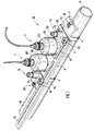
- Fig. 1 is a first variant of a perspective Clamp-On Ultrasonic Flowmeter Device 10 shown in the following briefly as clamp-on device 10 is designated. This is already on a pipe 1 attached in which a fluid flows, the Flow velocity and / or its volume flow is to be measured.
- the fluid is a liquid, a gas or a steam; the liquid can also contain solids contain.
- the clamp-on device 10 comprises a first one Sensor arrangement 2 and a second sensor arrangement 3. This are along a jacket line 11 of the pipeline 1 spaced apart and mirror images of each other attached, by means of a first or second, the Pipeline wrapping fixation tape 4, 5.
- Each of the two sensor arrangements 2, 3 comprises a first or a second boom 6, 7.
- the fixing straps 4, 5 are each with its own on the Back of the pipe 1 lying and therefore not provided, releasable closure provided. With these Closures are the fixing straps 4, 5 and thus also the respective sensor arrangement 2, 3 on the pipeline 1 so pre-buckled that the straps are still in the axial direction the pipe 1 are displaceable.
- FIG. 1 is also still a tool for adjustment of the two sensor arrangements 2, 3 at the optimal distance shown from each other.
- a perforated rod 8 with a first one and a second row of holes 81, 82 can by means of a first and a second tab device 83, 84 to the side of the two sensor arrangements 2, 3 temporarily or be firmly attached.
- One end of the first reaches into a hole in each row of holes or a second screw 85 or 86. Since the Row of holes 81 has a different pitch than row of holes 82 - e.g. the row of holes 81 has a nine division and the Row of holes 82 is a division of ten -, is by moving the perforated rod 81 opposite the tab devices 83, 84 and thus one sensor arrangement against the other one very precise adjustment of the mutual distance of the Sensor arrangements 2, 3 possible.
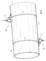
- Fig. 2 is a second variant of a perspective a pipe 1 'already attached clamp-on device 10 'with along diametrically opposite horizontal straight lines 11 ', 11 "of the pipeline 1' fixed sensor arrangements 2 ', 3' shown.
- the sensor arrangements 2 ', 3' are by means of a first or second fixing band 4 ', 5' wrapping around the pipeline in the manner described in explanation of FIG. 1 attached.
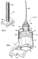
- Fig. 3 is a tensioner 75 with a perspective first end 751 shown. This indicates one Cross section of the fixing band 4, 4 'adapted bore 752 through which the fixing tape runs as a tape guide. Further the tensioner 75 has a threaded bolt 753 which is a represents second end.
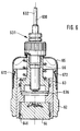
- FIG. 4 is a perspective and partially cut away the structure of the sensor arrangement 2 belonging to the invention, 2 'and 3, 3' shown.
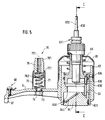
- 5 is a longitudinal section along a center line of the boom and in Fig. 6 one Side view in section along the line C-C of FIG. 5 shown. 4 to 6 are therefore in the following explained together.
- the flat boom 6 near the pipeline has one Central longitudinal axis 611 and one piece on it molded-on, tubular extension 62. On one of these End 61 facing away from the boom 6 on the Pipeline 1 or 1 '. At two points of contact with to reach the pipeline, the end 61 is not level, but rather angled.
- the Sensor insert 63 has a vertical axis 630 and contains an ultrasonic transducer 64 and the spring 66 in the belted state, as shown in FIGS. 1 and 2 is shown, pressed against the pipeline 1 or 1 '.
- a sensor hood 65 is slipped over the shoulder 62 and by means of a snap lock that can be released by twisting 67 attached to the neck 62.
- the sensor insert 63 ends preferably in a cable guide 631 for a connecting cable 632, on which the sensor hood 65 is rotatably attached. For aesthetic reasons, this indicates its scope equally distributed depressions 651.
- the Tensioner 70 has an axis 701 and includes one Coil spring 71, which is accommodated in a spring housing 72 is. This is by means of a central bore 73 having threaded approach 74 in the boom 6 on the Central longitudinal axis 611 attached.
- the tensioning device 70 also includes a nut 76 a hexagon or square head 761, which is in the spring housing 72 is rotatable and which for tensioning the fixing band 4, 4 ' or 5, 5 'on the threaded bolt 753 of Fig. 3rd is to be screwed on.
- the nut 76 and the coil spring 71 are expediently captive in the spring housing 72 arranged.
- the already pre-strapped, i.e. pre-tightened, Fixing tape 4, 4 'or 5, 5' is by turning the nut 76 finally clamped on the threaded bolt 753 and by means of the spiral spring 71 under a constant mechanical Preload set. This allows temperature-related Changes in length of the fixation tape in situ occur, intercept completely, so that the fixing straps can't loosen up.
- FIGS. 5 and 7 just like in FIG. 1 to see that at the end 61 of the boom 6 a screw-clamp connection 68 is provided. This serves for Connection of an earth or protective conductor line.
- FIG. 9 to 11 is in different views of the respective structure of used in the invention Ultrasound transducers shown.
- This is circular cylindrical and consists e.g. made of a high temperature thermoplastic material, such as e.g. an unfilled polyetherimide (PEI) as described under the trade name Ultem 1000 is available.
- PEI polyetherimide
- the substrate body 641 is provided with an annular groove 642 Recording an O-ring 646 provided that only in Fig. 5th to 8 is shown. Furthermore, the substrate body has 641 a flat support surface 643, which is in the strapped state rests on the pipeline 1 or 1 '.
- FIG. 10 shows the ultrasound transducer 64 in perspective of Fig. 9, as seen in the direction of its arrow A, and in Fig. 11 is a sectional view Seen in perspective along line B-B of Fig. 10.
- a transducer element 644 is located on the substrate body 641 Intermediate layer of a 645 metal disc glued on.
- the Converter element 644 is disc-shaped and consists of a ceramic piezoelectric material such as from one PZT-5 standard soft ceramic.
- the metal disc 645 has a coefficient of thermal expansion between that of the substrate body 641 and that of the transducer element 644 lies.
- the thickness of the metal disc 645 is at most one Quarter of the wavelength that is used Has ultrasonic oil in the metal disc 645. This exists preferably made of pure aluminum. But it can also e.g. out Titanium, stainless steel, brass or lead.
- Adhesives are particularly suitable as adhesives Epoxy resin base, one above the allowable Operating temperature of the ultrasonic transducer 64 lying Have glass transition temperature.
- Such adhesives are e.g. under the product names AV8 and AV118 from Ciba-Geigy, Basel / Switzerland available.
- the transducer element 644 and the metal disc 645 are in a plane 647, which is inclined to the support surface 643, is glued on. This forms the bottom surface of an oblique bore 648.
- the metal disk 645 is divided by three by approximately 120 ° each offset fingers 6451, 6452, 6453 self-centering with respect to the oblique bore 648. Furthermore, the metal disk 645 is by three against the Finger 6451 or 6452 or 6453 and by approx. 120 ° each offset noses 6454, 6455 and 6456 see above trained that through them the transducer element 644 also is centered. The three noses are from the plane of the Metal disc 645 bent out.
- the ultrasound transducer 64 and thus the entire clamp-on device 10, 10 'in one wide temperature range can be used without the Junction of transducer element and substrate body at Alternating temperature stress is destroyed. This is at Clamp-on arrangements are particularly important because of the temperature of fluids flowing in the pipeline 1 or 1 ' can fluctuate greatly.
- the ultrasonic transducer broadband than an ultrasonic transducer without Metal disc operated. Also the acoustic Adaptation between transducer element and substrate body improved due to the metal disc.
- FIGS. 5 to 8 show different preferred embodiments.
- the connecting cable 632 ends within the sensor insert 63 in a plug 635, which is inserted into a socket becomes. This is on a small printed circuit board 636, soldered to the leads of the converter element 644 are. In the preferred embodiment of FIGS. 5 and 6 there are no more on the 636 printed circuit board Components.
- FIGS. 7 and 8 is on the printed circuit board 636 arranged a series connection that consists of an air coil 637 and resistors 638 and the converter element 644 is electrically connected in parallel.
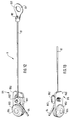
- FIG. 12 shows a first in a perspective top view Assembly aids 9 and Fig. 14 a second Assembly aids 9 'for precise adjustment of the clamp-on device according to Fig. 2.
- Figs. 13 and 15 show corresponding perspective partial bottom views.
- Two non-stretchable cords are used for this, e.g. from a thin steel cable, which is referred to below as a first and a second piece of rope 91, 91 '.
- a first and a second piece of rope 91, 91 ' are used for this, e.g. from a thin steel cable, which is referred to below as a first and a second piece of rope 91, 91 '.
- a first and a second piece of rope 91, 91 ' are used for this, e.g. from a thin steel cable, which is referred to below as a first and a second piece of rope 91, 91 '.
- the rope piece 91 in FIG. 12 and the rope piece in FIG. 14 Rope piece 91 'shown.
- a first end 92 of the rope piece 91 of FIG. 12 is in a first eyelet 93 permanently fixed, e.g. soldered or pressed.
- the bore 931 of the eyelet 93 has one Diameter slightly larger than the diameter of the 3, so that the eyelet 93rd pushed over with a light push and lightly Pull can be taken off again.
- a second end 94 of the rope piece 91 can be in a second Rope eyelet 95 can be temporarily fixed; thus the length of the rope piece 91 between the two rope eyes 93, 95 be adjusted.
- the rope eyelet 95 comprises a base plate 950, in one of which End of an eye 953 with a bore 954 is inserted.
- the Eye 953 is thicker than base plate 950.
- the hole 954 has a diameter that is slightly larger than that 3 is the diameter of the threaded bolt 753, so that the rope eyelet 95 is pushed over it with light pressure and can be removed again by pulling gently.
- the end 94 of the rope piece 91 can be by means of a Clamping piece 951 by screwing a screw 952 into the Secure base plate 950.
- the clamp 951 is located under the head of screw 952.
- a first end 92 'of the rope piece 91' of FIG. 14 is shown in FIG a first eyelet 93 'permanently fixed, e.g. soldered or pressed.
- the bore 931 'of the eyelet 93' has one Diameter slightly larger than the diameter of the 3 is such that the cable eyelet 93 ' pushed over with a light push and lightly Pull can be taken off again.
- a second end 94 'of the rope piece 91' can be in one second rope eyelet 95 'can be temporarily fixed; thus the Length of the rope piece 91 between the two rope eyes 93 ', 95 'can be adjusted.
- the rope eyelet 95 ' comprises a base plate 950', in the an eye 953 'is inserted at one end with a bore 954' is.
- the eye 953 ' is thicker than the base plate 950'.
- the Bore 954 ' has a diameter that is slightly larger than 3 is the diameter of the threaded bolt 753, so that the rope eyelet 95 'is pushed over with a slight push and can be removed again by pulling gently can.
- the end 94 'of the rope piece 91' can be by means of a Clamping piece 951 'by screwing a screw 952' into the Secure base plate 950 '.
- the clamp 951 ' is located under the head of screw 952 '.
- Distance A depends on several parameters, namely e.g. the diameter of the pipeline 1 ', its wall thickness, the type of fluid to be measured, its temperature etc.
- the wall thickness of the pipeline 1 'and the Type of fluid using known ultrasonic measuring methods be determined.
- Corresponding measuring arrangements can Be part of the clamp-on device 10, 10 '.
- the two pieces of rope 91, 91 ' are set to this value, by the end 94 or 94 'on the base plate 950 or 950 'by means of the screw 952 or 952' and the clamping piece 952 or 952 'is clamped.
- the fixing tape 5 ' is now in the axial direction Pipeline 1 'moved and at the same time in the direction of whose circumference is twisted until both rope pieces 91, 91 'are excited. In this case they are Sensor arrangements 2 ', 2' adjusted and by exactly 180 ° twisted against each other.
Priority Applications (1)
| Application Number | Priority Date | Filing Date | Title |
|---|---|---|---|
| EP99113687.0A EP0974815B1 (fr) | 1998-07-22 | 1999-07-15 | Capteur ultrasonique de débit à serrage |
Applications Claiming Priority (3)
| Application Number | Priority Date | Filing Date | Title |
|---|---|---|---|
| EP98113670 | 1998-07-22 | ||
| EP98113670 | 1998-07-22 | ||
| EP99113687.0A EP0974815B1 (fr) | 1998-07-22 | 1999-07-15 | Capteur ultrasonique de débit à serrage |
Publications (2)
| Publication Number | Publication Date |
|---|---|
| EP0974815A1 true EP0974815A1 (fr) | 2000-01-26 |
| EP0974815B1 EP0974815B1 (fr) | 2015-09-16 |
Family
ID=26149463
Family Applications (1)
| Application Number | Title | Priority Date | Filing Date |
|---|---|---|---|
| EP99113687.0A Expired - Lifetime EP0974815B1 (fr) | 1998-07-22 | 1999-07-15 | Capteur ultrasonique de débit à serrage |
Country Status (1)
| Country | Link |
|---|---|
| EP (1) | EP0974815B1 (fr) |
Cited By (13)
| Publication number | Priority date | Publication date | Assignee | Title |
|---|---|---|---|---|
| EP1396707A1 (fr) * | 2001-06-13 | 2004-03-10 | Fuji Electric Co., Ltd. | Instrument de mesure de debit d'ultrasons |
| DE10348676A1 (de) * | 2003-10-15 | 2005-05-12 | Flowtec Ag | Vorrichtung zur Bestimmung und/oder Überwachung des Volumen- und/oder Massendurchflusses eines Mediums in einer Rohrleitung |
| DE102005052550B3 (de) * | 2005-11-02 | 2007-02-08 | Krohne Ag | Clamp-on-Meßgerät |
| DE102006015217A1 (de) * | 2006-03-30 | 2007-10-11 | Krohne Ag | Ultraschalldurchflußmeßgerät |
| DE102007019689A1 (de) | 2007-04-24 | 2008-10-30 | Endress + Hauser Flowtec Ag | Vorrichtung zur Bestimmung und/oder Überwachung des Volumen- und/oder Massedurchflusses eines Mediums |
| DE102007019610A1 (de) * | 2007-04-24 | 2008-10-30 | Endress + Hauser Flowtec Ag | Vorrichtung zur Befestigung einer Mess- oder Anzeigeeinheit an einem Gegenstand |
| DE102007023802A1 (de) * | 2007-05-21 | 2008-11-27 | Endress + Hauser Flowtec Ag | Clamp-On Durchflussmessgerät zur Befestigung an einer Rohrleitung |
| WO2009130029A1 (fr) * | 2008-04-24 | 2009-10-29 | Eni S.P.A. | Procédé pour l'installation élastique de dispositifs de détection sur des canalisations et dispositif approprié pour celui-ci |
| CN102914334A (zh) * | 2012-09-29 | 2013-02-06 | 郑州光力科技股份有限公司 | 插入式超声波气体流量计 |
| GB2519643A (en) * | 2014-08-23 | 2015-04-29 | Kamran Iqbal | Flow monitor |
| DE102006062705B4 (de) * | 2006-03-30 | 2015-07-30 | Krohne Ag | Ultraschalldurchflußmeßgerät |
| DE102022103953A1 (de) | 2022-02-18 | 2023-08-24 | Endress+Hauser Flowtec Ag | Ultraschallwandler und Clamp-On-Ultraschall-Messgerät |
| US11982559B2 (en) | 2019-01-30 | 2024-05-14 | Labtrino Ab | Coupling member for clamp on flow metering |
Citations (3)
| Publication number | Priority date | Publication date | Assignee | Title |
|---|---|---|---|---|
| EP0198731A2 (fr) * | 1985-03-15 | 1986-10-22 | Framatome | Capteur pour ondes ultrasonores destiné à venir en contact avec une paroi à haute température et application de ce capteur |
| EP0334795A2 (fr) * | 1988-03-23 | 1989-09-27 | IRD MECHANALYSIS, Inc. | Montage d'un transducteur à vibrations |
| US5131278A (en) * | 1989-06-13 | 1992-07-21 | Joseph Baumoel | Mounting structure for transducers with sonic-energy absorbing means |
-
1999
- 1999-07-15 EP EP99113687.0A patent/EP0974815B1/fr not_active Expired - Lifetime
Patent Citations (3)
| Publication number | Priority date | Publication date | Assignee | Title |
|---|---|---|---|---|
| EP0198731A2 (fr) * | 1985-03-15 | 1986-10-22 | Framatome | Capteur pour ondes ultrasonores destiné à venir en contact avec une paroi à haute température et application de ce capteur |
| EP0334795A2 (fr) * | 1988-03-23 | 1989-09-27 | IRD MECHANALYSIS, Inc. | Montage d'un transducteur à vibrations |
| US5131278A (en) * | 1989-06-13 | 1992-07-21 | Joseph Baumoel | Mounting structure for transducers with sonic-energy absorbing means |
Cited By (21)
| Publication number | Priority date | Publication date | Assignee | Title |
|---|---|---|---|---|
| EP1396707A4 (fr) * | 2001-06-13 | 2006-01-25 | Fuji Electric Co Ltd | Instrument de mesure de debit d'ultrasons |
| EP1396707A1 (fr) * | 2001-06-13 | 2004-03-10 | Fuji Electric Co., Ltd. | Instrument de mesure de debit d'ultrasons |
| US7373839B2 (en) | 2003-10-15 | 2008-05-20 | Endress + Hauser Flowtec Ag | Apparatus for determining and/or monitoring volume- and/or mass-flow of a medium in a pipeline |
| DE10348676A1 (de) * | 2003-10-15 | 2005-05-12 | Flowtec Ag | Vorrichtung zur Bestimmung und/oder Überwachung des Volumen- und/oder Massendurchflusses eines Mediums in einer Rohrleitung |
| DE102005052550B3 (de) * | 2005-11-02 | 2007-02-08 | Krohne Ag | Clamp-on-Meßgerät |
| US7458279B2 (en) | 2005-11-02 | 2008-12-02 | Krohne Ag | Clamp-on measuring device |
| DE102006015217B4 (de) * | 2006-03-30 | 2008-01-24 | Krohne Ag | Ultraschalldurchflußmeßgerät |
| DE102006015217A1 (de) * | 2006-03-30 | 2007-10-11 | Krohne Ag | Ultraschalldurchflußmeßgerät |
| DE102006062705B4 (de) * | 2006-03-30 | 2015-07-30 | Krohne Ag | Ultraschalldurchflußmeßgerät |
| DE102007019610A1 (de) * | 2007-04-24 | 2008-10-30 | Endress + Hauser Flowtec Ag | Vorrichtung zur Befestigung einer Mess- oder Anzeigeeinheit an einem Gegenstand |
| US8267365B2 (en) | 2007-04-24 | 2012-09-18 | Endress + Hauser Flowtec Ag | Apparatus for securing a measuring or display unit on an object |
| DE102007019689A1 (de) | 2007-04-24 | 2008-10-30 | Endress + Hauser Flowtec Ag | Vorrichtung zur Bestimmung und/oder Überwachung des Volumen- und/oder Massedurchflusses eines Mediums |
| DE102007023802A1 (de) * | 2007-05-21 | 2008-11-27 | Endress + Hauser Flowtec Ag | Clamp-On Durchflussmessgerät zur Befestigung an einer Rohrleitung |
| EA021243B1 (ru) * | 2008-04-24 | 2015-05-29 | Эни С.П.А. | Способ упругой установки устройств обнаружения на трубопроводах и подходящее для этого устройство |
| WO2009130029A1 (fr) * | 2008-04-24 | 2009-10-29 | Eni S.P.A. | Procédé pour l'installation élastique de dispositifs de détection sur des canalisations et dispositif approprié pour celui-ci |
| US8549938B2 (en) | 2008-04-24 | 2013-10-08 | Eni S.P.A. | Method for the elastic installation of detection devices on pipelines and suitable device therefor |
| CN102914334A (zh) * | 2012-09-29 | 2013-02-06 | 郑州光力科技股份有限公司 | 插入式超声波气体流量计 |
| CN102914334B (zh) * | 2012-09-29 | 2015-04-29 | 郑州光力科技股份有限公司 | 插入式超声波气体流量计 |
| GB2519643A (en) * | 2014-08-23 | 2015-04-29 | Kamran Iqbal | Flow monitor |
| US11982559B2 (en) | 2019-01-30 | 2024-05-14 | Labtrino Ab | Coupling member for clamp on flow metering |
| DE102022103953A1 (de) | 2022-02-18 | 2023-08-24 | Endress+Hauser Flowtec Ag | Ultraschallwandler und Clamp-On-Ultraschall-Messgerät |
Also Published As
| Publication number | Publication date |
|---|---|
| EP0974815B1 (fr) | 2015-09-16 |
Similar Documents
| Publication | Publication Date | Title |
|---|---|---|
| DE2743394C3 (de) | Vorrichtung zur Befestigung eines für die Füllstandsmessung bestimmten Schall- oder Ultraschallwandlers an einem Behälter | |
| EP0974815B1 (fr) | Capteur ultrasonique de débit à serrage | |
| EP1780518B1 (fr) | Dispositif de fixation d'un débitmètre à pince | |
| DE2946826C2 (de) | Durchflußwächter für flüssige oder gasförmige Medien | |
| EP1840529A2 (fr) | Débimètre à ultrasons serre-tube | |
| DE2649357B2 (de) | Befestigung einer in einer Bohrung des Zylinderkopfes einer Brennkraftmaschine aufgenommenen Kraftstoffeinspritzdüse | |
| DE2022079A1 (de) | Befestigungselement mit Spannungsanzeigeeinrichtung sowie Verfahren und Vorrichtung zu deren Messung | |
| DE10230568B4 (de) | Vorrichtung und Baureihe von Vorrichtungen | |
| DE4233315A1 (de) | Vorrichtung zur Befestigung eines Gehäuses | |
| EP0402460B1 (fr) | Debitmetre electromagnetique | |
| EP0717267A1 (fr) | Dispositif de montage pour un capteur | |
| DE60314209T2 (de) | Verfahren und Vorrichtung zur Vermeidung von inneren Luftspalten in Gehäusen von magnetischen Sensoren | |
| DE4444831C2 (de) | Drucksensor | |
| WO2020083805A1 (fr) | Dispositif de mesure servant a définir le débit d'un fluide traversant un tronçon de tube | |
| DE3928733C2 (de) | Manometer mit schraubenförmig aufgewickelten Bourdonrohrspulen | |
| DE3134571A1 (de) | Schwingungsdensitometer | |
| EP1278999A1 (fr) | Capteur de mesure | |
| DE3038957C2 (de) | Anbaugehäuse zur Befestigung eines in einem Gehäuse angeordneten Geräts | |
| DE3416109A1 (de) | Einrichtung zur schwenk- und loesbaren verbindung zweier winkelig zueinander verlaufenden rohrleitungen | |
| DE202013005259U1 (de) | Messfühleranordnung | |
| EP0327103A2 (fr) | Débitmètre à fréquence de tourbillons | |
| EP0977018A1 (fr) | Arrangement d'électrodes pour débitmètres magnéto-inductives | |
| DE4007279C2 (de) | Anschlußvorrichtung für Einstutzen-Gaszähler | |
| DE3342797T1 (de) | Meßeinheit zur Messung des Gasdurchsatzes durch eine Leitung und in eine solche Meßeinheit einbaubare Meßvorrichtung | |
| DE102011014225A1 (de) | Durchflussmessgerät |
Legal Events
| Date | Code | Title | Description |
|---|---|---|---|
| PUAI | Public reference made under article 153(3) epc to a published international application that has entered the european phase |
Free format text: ORIGINAL CODE: 0009012 |
|
| AK | Designated contracting states |
Kind code of ref document: A1 Designated state(s): AT BE CH CY DE DK ES FI FR GB GR IE IT LI LU MC NL PT SE |
|
| AX | Request for extension of the european patent |
Free format text: AL;LT;LV;MK;RO;SI |
|
| 17P | Request for examination filed |
Effective date: 20000211 |
|
| D17P | Request for examination filed (deleted) | ||
| R17P | Request for examination filed (corrected) |
Effective date: 20000221 |
|
| AKX | Designation fees paid |
Free format text: AT BE CH CY DE DK ES FI FR GB GR IE IT LI LU MC NL PT SE |
|
| 17Q | First examination report despatched |
Effective date: 20071024 |
|
| GRAP | Despatch of communication of intention to grant a patent |
Free format text: ORIGINAL CODE: EPIDOSNIGR1 |
|
| INTG | Intention to grant announced |
Effective date: 20150421 |
|
| GRAS | Grant fee paid |
Free format text: ORIGINAL CODE: EPIDOSNIGR3 |
|
| GRAA | (expected) grant |
Free format text: ORIGINAL CODE: 0009210 |
|
| AK | Designated contracting states |
Kind code of ref document: B1 Designated state(s): AT BE CH CY DE DK ES FI FR GB GR IE IT LI LU MC NL PT SE |
|
| REG | Reference to a national code |
Ref country code: GB Ref legal event code: FG4D Free format text: NOT ENGLISH |
|
| REG | Reference to a national code |
Ref country code: CH Ref legal event code: EP |
|
| REG | Reference to a national code |
Ref country code: IE Ref legal event code: FG4D Free format text: LANGUAGE OF EP DOCUMENT: GERMAN |
|
| REG | Reference to a national code |
Ref country code: AT Ref legal event code: REF Ref document number: 750154 Country of ref document: AT Kind code of ref document: T Effective date: 20151015 |
|
| REG | Reference to a national code |
Ref country code: DE Ref legal event code: R096 Ref document number: 59915435 Country of ref document: DE |
|
| REG | Reference to a national code |
Ref country code: NL Ref legal event code: MP Effective date: 20150916 |
|
| PG25 | Lapsed in a contracting state [announced via postgrant information from national office to epo] |
Ref country code: GR Free format text: LAPSE BECAUSE OF FAILURE TO SUBMIT A TRANSLATION OF THE DESCRIPTION OR TO PAY THE FEE WITHIN THE PRESCRIBED TIME-LIMIT Effective date: 20151217 Ref country code: FI Free format text: LAPSE BECAUSE OF FAILURE TO SUBMIT A TRANSLATION OF THE DESCRIPTION OR TO PAY THE FEE WITHIN THE PRESCRIBED TIME-LIMIT Effective date: 20150916 |
|
| PG25 | Lapsed in a contracting state [announced via postgrant information from national office to epo] |
Ref country code: SE Free format text: LAPSE BECAUSE OF FAILURE TO SUBMIT A TRANSLATION OF THE DESCRIPTION OR TO PAY THE FEE WITHIN THE PRESCRIBED TIME-LIMIT Effective date: 20150916 |
|
| PG25 | Lapsed in a contracting state [announced via postgrant information from national office to epo] |
Ref country code: NL Free format text: LAPSE BECAUSE OF FAILURE TO SUBMIT A TRANSLATION OF THE DESCRIPTION OR TO PAY THE FEE WITHIN THE PRESCRIBED TIME-LIMIT Effective date: 20150916 |
|
| PG25 | Lapsed in a contracting state [announced via postgrant information from national office to epo] |
Ref country code: ES Free format text: LAPSE BECAUSE OF FAILURE TO SUBMIT A TRANSLATION OF THE DESCRIPTION OR TO PAY THE FEE WITHIN THE PRESCRIBED TIME-LIMIT Effective date: 20150916 |
|
| PG25 | Lapsed in a contracting state [announced via postgrant information from national office to epo] |
Ref country code: PT Free format text: LAPSE BECAUSE OF FAILURE TO SUBMIT A TRANSLATION OF THE DESCRIPTION OR TO PAY THE FEE WITHIN THE PRESCRIBED TIME-LIMIT Effective date: 20160118 |
|
| REG | Reference to a national code |
Ref country code: DE Ref legal event code: R097 Ref document number: 59915435 Country of ref document: DE |
|
| PLBE | No opposition filed within time limit |
Free format text: ORIGINAL CODE: 0009261 |
|
| STAA | Information on the status of an ep patent application or granted ep patent |
Free format text: STATUS: NO OPPOSITION FILED WITHIN TIME LIMIT |
|
| 26N | No opposition filed |
Effective date: 20160617 |
|
| PG25 | Lapsed in a contracting state [announced via postgrant information from national office to epo] |
Ref country code: DK Free format text: LAPSE BECAUSE OF FAILURE TO SUBMIT A TRANSLATION OF THE DESCRIPTION OR TO PAY THE FEE WITHIN THE PRESCRIBED TIME-LIMIT Effective date: 20150916 |
|
| PGFP | Annual fee paid to national office [announced via postgrant information from national office to epo] |
Ref country code: DE Payment date: 20160722 Year of fee payment: 18 |
|
| PG25 | Lapsed in a contracting state [announced via postgrant information from national office to epo] |
Ref country code: BE Free format text: LAPSE BECAUSE OF NON-PAYMENT OF DUE FEES Effective date: 20160731 |
|
| REG | Reference to a national code |
Ref country code: CH Ref legal event code: PL |
|
| GBPC | Gb: european patent ceased through non-payment of renewal fee |
Effective date: 20160715 |
|
| PG25 | Lapsed in a contracting state [announced via postgrant information from national office to epo] |
Ref country code: MC Free format text: LAPSE BECAUSE OF FAILURE TO SUBMIT A TRANSLATION OF THE DESCRIPTION OR TO PAY THE FEE WITHIN THE PRESCRIBED TIME-LIMIT Effective date: 20150916 |
|
| PG25 | Lapsed in a contracting state [announced via postgrant information from national office to epo] |
Ref country code: FR Free format text: LAPSE BECAUSE OF NON-PAYMENT OF DUE FEES Effective date: 20160801 Ref country code: LI Free format text: LAPSE BECAUSE OF NON-PAYMENT OF DUE FEES Effective date: 20160731 Ref country code: CH Free format text: LAPSE BECAUSE OF NON-PAYMENT OF DUE FEES Effective date: 20160731 |
|
| REG | Reference to a national code |
Ref country code: FR Ref legal event code: ST Effective date: 20170331 |
|
| REG | Reference to a national code |
Ref country code: IE Ref legal event code: MM4A |
|
| PG25 | Lapsed in a contracting state [announced via postgrant information from national office to epo] |
Ref country code: GB Free format text: LAPSE BECAUSE OF NON-PAYMENT OF DUE FEES Effective date: 20160715 |
|
| PG25 | Lapsed in a contracting state [announced via postgrant information from national office to epo] |
Ref country code: IE Free format text: LAPSE BECAUSE OF NON-PAYMENT OF DUE FEES Effective date: 20160715 |
|
| PG25 | Lapsed in a contracting state [announced via postgrant information from national office to epo] |
Ref country code: LU Free format text: LAPSE BECAUSE OF NON-PAYMENT OF DUE FEES Effective date: 20160715 Ref country code: IT Free format text: LAPSE BECAUSE OF NON-PAYMENT OF DUE FEES Effective date: 20160715 |
|
| REG | Reference to a national code |
Ref country code: AT Ref legal event code: MM01 Ref document number: 750154 Country of ref document: AT Kind code of ref document: T Effective date: 20160715 |
|
| PG25 | Lapsed in a contracting state [announced via postgrant information from national office to epo] |
Ref country code: AT Free format text: LAPSE BECAUSE OF NON-PAYMENT OF DUE FEES Effective date: 20160715 |
|
| REG | Reference to a national code |
Ref country code: DE Ref legal event code: R119 Ref document number: 59915435 Country of ref document: DE |
|
| PG25 | Lapsed in a contracting state [announced via postgrant information from national office to epo] |
Ref country code: DE Free format text: LAPSE BECAUSE OF NON-PAYMENT OF DUE FEES Effective date: 20180201 |
|
| PG25 | Lapsed in a contracting state [announced via postgrant information from national office to epo] |
Ref country code: CY Free format text: LAPSE BECAUSE OF FAILURE TO SUBMIT A TRANSLATION OF THE DESCRIPTION OR TO PAY THE FEE WITHIN THE PRESCRIBED TIME-LIMIT Effective date: 20150916 |