EP0974815A1 - Clamp-on ultrasonic sensor arrangement - Google Patents
Clamp-on ultrasonic sensor arrangement Download PDFInfo
- Publication number
- EP0974815A1 EP0974815A1 EP99113687A EP99113687A EP0974815A1 EP 0974815 A1 EP0974815 A1 EP 0974815A1 EP 99113687 A EP99113687 A EP 99113687A EP 99113687 A EP99113687 A EP 99113687A EP 0974815 A1 EP0974815 A1 EP 0974815A1
- Authority
- EP
- European Patent Office
- Prior art keywords
- sensor
- clamp
- pipeline
- sensor arrangement
- fixing band
- Prior art date
- Legal status (The legal status is an assumption and is not a legal conclusion. Google has not performed a legal analysis and makes no representation as to the accuracy of the status listed.)
- Granted
Links
Images


Classifications
-
- G—PHYSICS
- G01—MEASURING; TESTING
- G01F—MEASURING VOLUME, VOLUME FLOW, MASS FLOW OR LIQUID LEVEL; METERING BY VOLUME
- G01F1/00—Measuring the volume flow or mass flow of fluid or fluent solid material wherein the fluid passes through a meter in a continuous flow
- G01F1/66—Measuring the volume flow or mass flow of fluid or fluent solid material wherein the fluid passes through a meter in a continuous flow by measuring frequency, phase shift or propagation time of electromagnetic or other waves, e.g. using ultrasonic flowmeters
- G01F1/662—Constructional details
-
- G—PHYSICS
- G10—MUSICAL INSTRUMENTS; ACOUSTICS
- G10K—SOUND-PRODUCING DEVICES; METHODS OR DEVICES FOR PROTECTING AGAINST, OR FOR DAMPING, NOISE OR OTHER ACOUSTIC WAVES IN GENERAL; ACOUSTICS NOT OTHERWISE PROVIDED FOR
- G10K11/00—Methods or devices for transmitting, conducting or directing sound in general; Methods or devices for protecting against, or for damping, noise or other acoustic waves in general
- G10K11/004—Mounting transducers, e.g. provided with mechanical moving or orienting device
-
- G—PHYSICS
- G01—MEASURING; TESTING
- G01S—RADIO DIRECTION-FINDING; RADIO NAVIGATION; DETERMINING DISTANCE OR VELOCITY BY USE OF RADIO WAVES; LOCATING OR PRESENCE-DETECTING BY USE OF THE REFLECTION OR RERADIATION OF RADIO WAVES; ANALOGOUS ARRANGEMENTS USING OTHER WAVES
- G01S7/00—Details of systems according to groups G01S13/00, G01S15/00, G01S17/00
- G01S7/52—Details of systems according to groups G01S13/00, G01S15/00, G01S17/00 of systems according to group G01S15/00
- G01S7/521—Constructional features
Landscapes
- Physics & Mathematics (AREA)
- Electromagnetism (AREA)
- Fluid Mechanics (AREA)
- General Physics & Mathematics (AREA)
- Engineering & Computer Science (AREA)
- Acoustics & Sound (AREA)
- Multimedia (AREA)
- Investigating Or Analyzing Materials By The Use Of Ultrasonic Waves (AREA)
- Measuring Volume Flow (AREA)
Abstract
Description
Die Erfindung beschäftigt sich mit der Schaffung von Clamp-On-Ultraschall-Durchflußaufnehmer-Vorrichtungen.The invention is concerned with the creation of clamp-on ultrasonic flowmeter devices.
Derartige Ultraschall-Durchflußaufnehmer-Vorrichtungen werden bekanntlich von außen an einer, insb. bereits innerhalb eines Rohrleitungssystems fest installierten, Rohrleitung befestigt, ohne an dieser eine Veränderung vornehmen, z.B. eine Bohrung anbringen, zu müssen. Es ist auch kein eigens hergerichtetes Meßrohr erforderlich, wie dies bei anderen Durchfluß-Meßprinzipien, z.B. bei Vortex-Durchflußmessern, magnetisch-induktiven Durchflußmessern oder Coriolis-Massedurchflußmessern, üblich ist.Such ultrasonic flowmeter devices are known to be on the outside, especially already permanently installed within a piping system, Pipe attached without making any change to it make, e.g. to drill a hole. It is also no specially prepared measuring tube required, such as this with other flow measuring principles, e.g. with vortex flow meters, magnetic-inductive flow meters or Coriolis mass flow meters is common.
In der US-A 38 69 915 ist eine Clamp-On-Ultraschall-Durchflußaufnehmer-Vorrichtung beschrieben mit einer zwei Sensoren enthaltenden Sensoranordnung, die entlang einer Mantellinie einer Rohrleitung, in der ein zu messendes Fluid strömt, mittels eines ersten bzw. zweiten, die Rohrleitung umschlingenden Fixierbandes voneinander beabstandet befestigt ist.In US-A 38 69 915 is a clamp-on ultrasonic flowmeter device described with a two Sensor-containing sensor arrangement that runs along a Surface line of a pipeline, in which a to be measured Fluid flows by means of a first and a second, respectively Pipe wrapping fixation tape from each other is attached spaced.
In der einzigen Figur der US-A 47 38 737, nicht jedoch in deren Beschreibung ist ferner eine Clamp-On-Ultraschall-Durchflußaufnehmer-Vorrichtung offenbart mit einer ersten und einer zweiten Sensoranordnung,
- von welchen die erste entlang einer ersten Mantelgerade der Rohrleitung und die zweite entlang einer der ersten im wesentlichen gegenüberliegenden zweiten Mantelgerade mittels eines ersten und zweiten bzw. eines dritten und vierten, die Rohrleitung umschlingenden Fixierbandes voneinander beabstandet befestigt sind und
- welche beide identisch zueinander aufgebaut sind.
- of which the first along a first casing line of the pipeline and the second along a first substantially opposite second casing straight line are fastened at a distance from one another by means of a first and second or a third and fourth fixing band wrapping around the pipeline and
- which are both identical to each other.
Die letzgenannte US-A beschreibt nicht, wie die beiden Sensoranordnungen, wenn sie an einander gegenüberliegenden Mantelgeraden angeordnet sind, zueinander ausgerichtet wurden oder wie die beiden Sensoranordnungen entlang einer einzigen Mantelgerade beabstandet voneinander anzuordnen sind.The latter US-A does not describe how the two Sensor arrays when facing each other Sheath lines are arranged, aligned with each other were or like the two sensor arrangements along one single jacket line spaced from each other are.
Eine Aufgabe der Erfindung besteht darin, eine aus einer ersten und einer zweiten Sensoranordnung bestehende, verbesserte Clamp-On-Ultraschall-Durchflußaufnehmer-Vorrichtung anzugeben, die für unterschiedliche Nennweiten von Rohrleitungen verwendbar ist und die entweder entlang einer einzigen Mantelgerade oder entlang von diametral einander gegenüberliegenden Mantelgeraden fixierbar ist.An object of the invention is one of a first and a second sensor arrangement, Improved clamp-on ultrasonic flowmeter device specify that for different nominal sizes of pipes is usable and either along a single straight line or along diametrical mutually opposite straight lines can be fixed.
Ferner soll die Clamp-On-Ultraschall-Durchflußaufnehmer-Vorrichtung so aufgebaut sein, daß sie auswechselbare Komponenten enthält, so daß im Bedarfsfall lediglich defekte Einzelkomponenten ersetzt zu werden brauchen.Furthermore, the clamp-on ultrasonic flowmeter device be constructed so that they are interchangeable Contains components, so that if necessary only defective individual components need to be replaced.
Zur Lösung dieser Aufgaben besteht die Erfindung in einer Clamp-On-Ultraschall-Durchflußaufnehmer-Vorrichtung mit einer ersten und einer zweiten Sensoranordnung,
- von welchen
- entweder beide entlang einer Mantelgerade einer Rohrleitung, in der ein zu messendes Fluid strömt,
- oder die erste Sensoranordnung entlang einer ersten Mantelgerade der Rohrleitung und die zweite Sensoranordnung entlang einer der ersten diametral gegenüberliegenden zweiten Mantelgerade
- mittels eines ersten bzw. zweiten, die Rohrleitung umschlingenden Fixierbandes voneinander beabstandet befestigt sind und
- welche beide Sensoranordnungen identisch zueinander
aufgebaut sind und jeweils umfassen:
- einen rohrleitungsnahen flachen Ausleger mit einer Mittellängsachse und einen einstückig daran angeformten, rohrförmigen Ansatz,
- einen im Ansatz längsgeführten Sensoreinsatz, der einen Ultraschall-Wandler mit einem Wandlerelement enthält,
- eine Sensorhaube, die
- über den Ansatz gestülpt ist,
- mittels eines durch Verdrehen lösbaren Schnappverschlusses am Ansatz befestigt ist und
- eine Feder umfaßt, die den Sensoreinsatz gegen die Rohrleitung drückt, und
- eine etwa in der Mitte der Mittellängsachse des Auslegers darin fixierte, eine Achse aufweisende Spannvorrichtung für das Fixierband.
- from which
- either both along a straight line of a pipeline in which a fluid to be measured flows,
- or the first sensor arrangement along a first jacket line of the pipeline and the second sensor arrangement along one of the first diametrically opposite second jacket line
- are fastened at a distance from one another by means of a first or a second fixing band which wraps around the pipeline and
- which two sensor arrangements are identical to each other and each include:
- a flat boom near the pipeline with a central longitudinal axis and a tubular extension integrally molded thereon,
- a longitudinally guided sensor insert, which contains an ultrasonic transducer with a transducer element,
- a sensor hood that
- put on the approach
- is attached to the attachment by means of a snap lock which can be released by twisting and
- comprises a spring which presses the sensor insert against the pipeline, and
- an approximately in the middle of the central longitudinal axis of the boom fixed therein, having an axis tensioning device for the fixing band.
Nach einer ersten bevorzugten Ausgestaltung der Erfindung endet der Sensoreinsatz in einer Kabelführung und die Sensorhaube ist auf der Kabelführung drehbar befestigt.According to a first preferred embodiment of the invention the sensor insert ends in a cable duct and the Sensor hood is rotatably attached to the cable guide.
Nach einer zweiten bevorzugten Ausgestaltung der Erfindung, die auch bei der ersten Ausgestaltung anwendbar ist, umfaßt die Spannvorrichtung:
- eine Spiralfeder,
- ein Federgehäuse, das mittels eines eine Zentralbohrung aufweisenden Gewindeansatzes im Ausleger auf dessen Mittellängsachse befestigt ist,
- einen Spanner mit einem ersten Ende, durch das als Bandführung das Fixierband läuft, und mit einem als Gewindebolzen ausgebildeten zweiten Ende und
- eine Mutter, die im Federgehäuse drehbar ist und die zum Spannen des Fixierbandes auf den Gewindebolzen aufgeschraubt ist.
- a coil spring,
- a spring housing which is fastened in the boom on its central longitudinal axis by means of a threaded attachment having a central bore,
- a tensioner with a first end through which the fixing band runs as a band guide, and with a second end designed as a threaded bolt and
- a nut which is rotatable in the spring housing and which is screwed onto the threaded bolt for tensioning the fixing strap.
Nach einer dritten bevorzugten Ausgestaltung der Erfindung, die auch bei der ersten oder der zweiten Ausgestaltung anwendbar ist, ist innerhalb des Sensoreinsatzes mindestens eine aus einer Luftspule und mindestens einem Widerstand bestehende Serienschaltung in der Nähe des Ultraschall-Wandlers angeordnet, und diese ist dem Wandlerelement parallelgeschaltet.According to a third preferred embodiment of the invention, which also applies to the first or the second embodiment is applicable, is at least within the sensor insert one from an air coil and at least one resistor existing series connection near the ultrasonic transducer arranged, and this is the transducer element connected in parallel.
Ein wesentlicher Vorteil der Erfindung besteht darin, daß sie eine Clamp-On-Ultraschall-Durchflußaufnehmer-Vorrichtung schafft, die allen Montage-, Justier- und Reparatur-Anforderungen genügt.A major advantage of the invention is that a clamp-on ultrasonic flowmeter device creates all assembly, adjustment and Repair requirements are sufficient.
Die Erfindung wird nun anhand der Figuren der Zeichnung näher erläutert, in der bevorzugte Ausführungsbeispiele dargestellt sind.
- Fig. 1
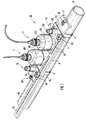
- zeigt perspektivisch eine erste Variante einer an einer Rohrleitung bereits angebrachten Clamp-On-Ultraschall-Durchflußaufnehmer-Vorrichtung mit entlang einer Mantelgerade der Rohrleitung fixierten Sensoranordnungen,
- Fig. 2
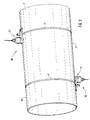
- zeigt perspektivisch eine zweite Variante einer an einer Rohrleitung bereits angebrachten Clamp-On-Ultraschall-Durchflußaufnehmer-Vorrichtung mit entlang von diametral gegenüberliegenden Mantelgeraden der Rohrleitung fixierten Sensoranordnungen,
- Fig. 3
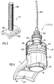
- zeigt perspektivisch einen Spanner als Teil einer bei der Erfindung verwendeten Spannvorrichtung,
- Fig. 4
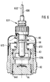
- zeigt perspektivisch und teilweise aufgeschnitten den Aufbau einer zur Erfindung gehörenden Sensoranordnung,
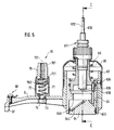
- Fig. 5
- zeigt im Längsschnitt entlang einer Mittellinie des Auslegers eine bevorzugte Ausgestaltung der Sensoranordnung von Fig. 4,
- Fig. 6
- zeigt im Schnitt entlang der Linie C-C eine Seitenansicht der Sensoranordnung von Fig. 5,
- Fig. 7
- zeigt im Längsschnitt entlang einer Mittellinie des Auslegers eine andere bevorzugte Ausgestaltung der Sensoranordnung von Fig. 4,
- Fig. 8
- zeigt im Schnitt entlang der Linie C-C eine Seitenansicht der Sensoranordnung von Fig. 7,
- Fig. 9
- zeigt in Seitenansicht einen bei der Erfindung verwendeten Ultraschall-Wandler,
- Fig. 10
- zeigt perspektivisch den Ultraschall-Wandler der Fig. 9, gesehen in Richtung von deren Pfeil A,
- Fig. 11
- zeigt perspektivisch und in Schnittansicht entlang
der Linie B-B von Fig. 10 den Ultraschall-Wandler
der Fig. 9
und 10, - Fig. 12
- zeigt in perspektivischer Draufsicht ein erstes Montagehilfsmittel zur genauen Justierung einer Clamp-On-Ultraschall-Durchflußaufnehmer-Vorrichtung nach Fig. 2,
- Fig. 13
- zeigt in perspektivischer Unteransicht ein Detail von Fig. 12,
- Fig. 14
- zeigt in perspektivischer Draufsicht ein zweites Montagehilfsmittel zur genauen Justierung einer Clamp-On-Ultraschall-Durchflußaufnehmer-Vorrichtung nach Fig. 2, und
- Fig. 15
- zeigt in perspektivischer Unteransicht ein Detail von Fig. 14.
- Fig. 1
- 1 shows a perspective view of a first variant of a clamp-on ultrasound flow sensor device already attached to a pipeline with sensor arrangements fixed along a straight line of the pipeline
- Fig. 2
- 1 shows, in perspective, a second variant of a clamp-on ultrasonic flowmeter device already attached to a pipeline with sensor arrangements fixed along diametrically opposite jacket lines of the pipeline,
- Fig. 3
- shows a perspective view of a tensioner as part of a tensioning device used in the invention,
- Fig. 4
- shows in perspective and partially cut away the structure of a sensor arrangement belonging to the invention,
- Fig. 5
- FIG. 4 shows a preferred embodiment of the sensor arrangement from FIG. 4 in a longitudinal section along a center line of the cantilever,
- Fig. 6
- shows a section along the line CC a side view of the sensor arrangement of FIG. 5,
- Fig. 7
- 4 shows another preferred embodiment of the sensor arrangement from FIG. 4 in a longitudinal section along a center line of the cantilever,
- Fig. 8
- shows a section along the line CC a side view of the sensor arrangement of FIG. 7,
- Fig. 9
- shows a side view of an ultrasonic transducer used in the invention,
- Fig. 10
- shows in perspective the ultrasonic transducer of FIG. 9, seen in the direction of the arrow A,
- Fig. 11
- FIG. 10 shows the ultrasonic transducer of FIGS. 9 and 10 in perspective and in a sectional view along line BB of FIG. 10,
- Fig. 12
- FIG. 2 shows a perspective top view of a first assembly aid for precise adjustment of a clamp-on ultrasonic flowmeter device according to FIG. 2,
- Fig. 13
- shows a perspective bottom view of a detail of FIG. 12,
- Fig. 14
- shows a perspective top view of a second assembly aid for precise adjustment of a clamp-on ultrasonic flowmeter device according to FIG. 2, and
- Fig. 15
- 14 shows a detail from FIG. 14 in a perspective bottom view.
In Fig. 1 ist perspektivisch eine erste Variante einer
Clamp-On-Ultraschall-Durchflußaufnehmer-Vorrichtung 10
gezeigt, die im folgenden kurz als Clamp-On-Vorrichtung 10
bezeichnet ist. Diese ist an einer Rohrleitung 1 bereits
angebracht, in der ein Fluid strömt, dessen
Strömungsgeschwindigkeit und/oder dessen Volumendurchfluß
zu messen ist. Das Fluid ist eine Flüssigkeit, ein Gas oder
ein Dampf; die Flüssigkeit kann auch Festkörperanteile
enthalten.In Fig. 1 is a first variant of a perspective
Clamp-On
Die Clamp-On-Vorrichtung 10 umfaßt eine erste
Sensoranordnung 2 und eine zweite Sensoranordnung 3. Diese
sind entlang einer Mantelgerade 11 der Rohrleitung 1
voneinander beabstandet und spiegelbbildlich zueinander
befestigt, und zwar mittels eines ersten bzw. zweiten, die
Rohrleitung umschlingenden Fixierbandes 4, 5. Jede der
beiden Sensoranordnungen 2, 3 umfaßt einen ersten bzw.
einen zweiten Ausleger 6, 7.The clamp-on
Die Fixierbänder 4, 5 sind mit einem je eigenen, auf der
Rückseite der Rohrleitung 1 liegenden und somit nicht
dargestellten, lösbaren Verschluß versehen. Mit diesen
Verschlüssen werden die Fixierbänder 4, 5 und damit auch
die jeweilige Sensoranordnung 2, 3 auf der Rohrleitung 1 so
vor-angeschnallt, daß die Fixierbänder noch in Achsrichtung
der Rohrleitung 1 verschiebbar sind.The fixing straps 4, 5 are each with its own on the
Back of the pipe 1 lying and therefore not
provided, releasable closure provided. With these
Closures are the fixing
In Fig. 1 ist ferner noch ein Hilfsmittel zur Justierung
der beiden Sensoranordnungen 2, 3 im optimalen Abstand
voneinander dargestellt. Eine Lochstange 8 mit einer ersten
und einer zweiten Lochreihe 81, 82 kann mittels einer
ersten bzw. einer zweiten Laschenvorrichtung 83, 84
seitlich der beiden Sensoranordnungen 2, 3 temporär oder
fest angebracht werden.In Fig. 1 is also still a tool for adjustment
of the two
In ein Loch jeder Lochreihe greift ein Ende einer ersten
bzw. einer zweiten Schraube 85 bzw. 86 ein. Da die
Lochreihe 81 eine andere Teilung als die Lochreihe 82 hat
- z.B. hat die Lochreihe 81 eine Neunerteilung und die
Lochreihe 82 eine Zehnerteilung -, ist durch Verschieben
der Lochstange 81 gegenüber den Laschenvorrichtungen 83, 84
und damit der einen Sensoranordnung gegen die andere eine
sehr genaue Einstellung des gegenseitigen Abstands der
Sensoranordnungen 2, 3 möglich.One end of the first reaches into a hole in each row of holes
or a
In Fig. 2 ist perspektivisch eine zweite Variante einer an
einer Rohrleitung 1' bereits angebrachten Clamp-On-Vorrichtung
10' mit entlang von diametral gegenüber
liegenden Mantelgeraden 11', 11" der Rohrleitung 1'
fixierten Sensoranordnungen 2', 3' gezeigt. Im Vergleich
mit der Anordnung von Fig. 1 ist der Durchmesser der
Rohrleitung 1' wesentlich größer als der Durchmesser der
Rohrleitung 1. Deshalb sind die Sensoranordnungen 2', 3'
gegenüber den Sensoranordnungen 2, 3 von Fig. 1 kleiner
dargestellt, obwohl es sich um gleiche Sensoranordnungen
handelt. In Fig. 2 is a second variant of a perspective
a pipe 1 'already attached clamp-on device
10 'with along diametrically opposite
horizontal
Die Sensoranordnungen 2', 3' sind mittels eines ersten bzw. zweiten, die Rohrleitung umschlingenden Fixierbandes 4', 5' in der bei Erläuterung der Fig. 1 beschriebenen Weise befestigt.The sensor arrangements 2 ', 3' are by means of a first or second fixing band 4 ', 5' wrapping around the pipeline in the manner described in explanation of FIG. 1 attached.
In Fig. 3 ist perspektivisch ein Spanner 75 mit einem
ersten Ende 751 dargestellt. Dieses weist eine dem
Querschnitt des Fixierbandes 4, 4' angepaßte Bohrung 752
auf, durch die als Bandführung das Fixierband läuft. Ferner
weist der Spanner 75 einen Gewindebolzen 753 auf, der ein
zweites Ende darstellt.In Fig. 3 is a
In Fig. 4 ist perspektivisch und teilweise aufgeschnitten
der Aufbau der zur Erfindung gehörenden Sensoranordnung 2,
2' bzw. 3, 3' gezeigt. In Fig. 5 sind ein Längsschnitt
entlang einer Mittellinie des Auslegers und in Fig. 6 eine
Seitenansicht im Schnitt entlang der Linie C-C von Fig. 5
dargestellt. Die Fig. 4 bis 6 werden daher im folgenden
gemeinsam erläutert.4 is a perspective and partially cut away
the structure of the
Der rohrleitungsnahe, flache Ausleger 6 hat eine
Mittellängsachse 611 und einen einstückig daran
angeformten, rohrförmigen Ansatz 62. An einem von diesem
abgewandten Ende 61 liegt der Ausleger 6 auf der
Rohrleitung 1 bzw. 1' auf. Um zwei Berührungsstellen mit
der Rohrleitung zu erreichen, ist das Ende 61 nicht eben,
sondern leicht abgewinkelt ausgebildet.The flat boom 6 near the pipeline has one
Central longitudinal axis 611 and one piece on it
molded-on,
Im Ansatz 62 läßt sich ein in einer Nut 633 von einer Nase
634 längsgeführter Sensoreinsatz 63 gegen eine Feder 66,
insb. eine Spiralfeder, hin- und herbewegen. Der
Sensoreinsatz 63 hat eine Vertikalachse 630 und enthält
einen Ultraschall-Wandler 64 und wird von der Feder 66 im
angeschnallten Zustand, wie er in den Fig. 1 und 2
dargestellt ist, gegen die Rohrleitung 1 bzw. 1' gedrückt. In the
Eine Sensorhaube 65 ist über den Ansatz 62 gestülpt und
mittels eines durch Verdrehen lösbaren Schnappverschlusses
67 am Ansatz 62 befestigt. Der Sensoreinsatz 63 endet
bevorzugt in einer Kabelführung 631 für ein Anschlußkabel
632, auf der die Sensorhaube 65 drehbar befestigt ist.
Diese weist aus ästhetischen Gründen auf ihrem Umfang
gleichverteilte Vertiefungen 651 auf.A
In Fig. 4 sind ferner zum Schappverschluß 67 gehörende
Vertiefungen 671 und in den Fig. 4 und 6 dazu gehörende
Blattfedern 672 zu sehen. Durch Niederdrücken zur
Rohrleitung 1 hin und Verdrehen läßt sich die Sensorhaube
65 vom Ansatz 62 lösen. Dadurch wird der Ultraschall-Wandler
64 zugänglich und kann gegebenenfalls ausgewechselt
werden.4 also belong to the
Etwa in der Mitte der Mittellängsachse 61 des Auslegers 6
ist eine Spannvorrichtung 70 für das Fixierband 4
angebracht, die nur in den Fig. 5 und dargestellt, dagegen
in den Fig. 4, 6 und 8 nicht zusehen ist. Die
Spannvorrichtung 70 hat eine Achse 701 und umfaßt eine
Spiralfeder 71, die in einem Federgehäuse 72 untergebracht
ist. Dieses ist mittels eines eine Zentralbohrung 73
aufweisenden Gewindeansatzes 74 im Ausleger 6 auf dessen
Mittellängsachse 611 befestigt.Approximately in the middle of the central
Die Spannvorrichtung 70 umfaßt ferner eine Mutter 76 mit
einem Sechskant- oder Vierkantkopf 761, die im Federgehäuse
72 drehbar ist und die zum Spannen des Fixierbandes 4, 4'
bzw. 5, 5' auf den Gewindebolzen 753 von Fig. 3
aufzuschrauben ist. Die Mutter 76 und die Spiralfeder 71
sind zweckmäßigerweise unverlierbar im Federgehäuse 72
angeordnet. The
Dies kann, wie in den Fig. 5 und 7 dargestellt ist, z.B.
dadurch erreicht werden, daß die Mutter 76 an einem inneren
Ende mit einem Bund 762 versehen ist und daß nach dem
Einsetzen von Spiralfeder 71 und Mutter 76 in das
Federgehäuse 72 letzteres an seinem der Mutter 76
zugewandten Ende 721 nach innen umgebördelt wird.This can, as shown in Figs. 5 and 7, e.g.
can be achieved in that the
Das bereits vor-angeschnallte, also vor-festgespannte,
Fixierband 4, 4' bzw. 5, 5' wird durch Verdrehen der Mutter
76 auf dem Gewindebolzen 753 endgültig festgespannt und
mittels der Spiralfeder 71 unter eine ständige mechanische
Vorspannung gesetzt. Dadurch lassen sich temperaturbedingte
Längenänderungen des Fixierbandes, die in situ
auftreten, vollständig abfangen, so daß die Fixierbänder
sich nicht lockern können.The already pre-strapped, i.e. pre-tightened,
Fixing
In Fig. 5 und 7 ist ebenso wie in Fig. 1 schließlich noch
zu sehen, daß am Ende 61 des Auslegers 6 eine Schraub-Klemm-Verbindung
68 vorgesehen ist. Diese dient zum
Anschluß einer Erdungs- bzw. einer Schutzleiter-Leitung.Finally, in FIGS. 5 and 7, just like in FIG. 1
to see that at the
In den Fig. 9 bis 11 ist in unterschiedlichen Ansichten der
jeweilige Aufbau von bei der Erfindung verwendeten
Ultraschall-Wandlern dargestellt. In der Seitenansicht der
Fig. 9 ist vom Ultraschall-Wandler 64 ein Substratkörper
641 zu sehen. Dieser ist kreiszylindrisch und besteht z.B.
aus einem hochtemperatur-thermoplastischen Material, wie
z.B. einem unverfüllten Polyetherimid (PEI), wie es unter
dem Handelsnamen Ultem 1000 erhältlich ist.9 to 11 is in different views of the
respective structure of used in the invention
Ultrasound transducers shown. In the side view of the
9 is a substrate body of the
Der Substratkörper 641 ist mit einer Ringnut 642 zur
Aufnahme eines O-Rings 646 versehen, der nur in den Fig. 5
bis 8 dargestellt ist. Ferner hat der Substratkörper 641
eine ebene Auflagefläche 643, die im angeschnallten Zustand
auf der Rohrleitung 1 bzw. 1' aufliegt. The
In Fig. 10 ist perspektivisch der Ultraschall-Wandler 64
von Fig. 9 dargestellt, und zwar gesehen in Richtung von
deren Pfeil A, und in Fig. 11 ist eine Schnittansicht
entlang der Linie B-B von Fig. 10 perspektivisch zu sehen.10 shows the
Auf dem Substratkörper 641 ist ein Wandlerelement 644 unter
Zwischenlage einer Metallscheibe 645 aufgeklebt. Das
Wandlerelement 644 ist scheibenförmig und besteht aus einem
keramischen piezoelektrischen Material, wie z.B. aus einer
PZT-5-Standard-Soft-Keramik. Die Metallscheibe 645 hat
einen thermischen Ausdehnungskoeffizienten, der zwischen
dem des Substratkörpers 641 und dem des Wandlerelements 644
liegt.A
Die Dicke der Metallscheibe 645 ist höchstens gleich einem
Viertel der Wellenlänge, die der zur Anwendung gelangende
Ultraschalll in der Metallscheibe 645 hat. Diese besteht
bevorzugt aus Rein-Aluminium. Sie kann aber auch z.B. aus
Titan, Edelstahl, Messing oder Blei bestehen.The thickness of the
Als Klebstoffe eignen sich besonders gut Kleber auf
Epoxidharzbasis, die eine oberhalb der zulässigen
Betriebstemperatur des Ultraschall-Wandlers 64 liegende
Glasübergangstemperatur aufweisen. Solche Kleber sind z.B.
unter den Produktbezeichnungen AV8 und AV118 von der Fa.
Ciba-Geigy, Basel/Schweiz erhältlich.Adhesives are particularly suitable as adhesives
Epoxy resin base, one above the allowable
Operating temperature of the
Das Wandlerelement 644 und die Metallscheibe 645 sind in
einer zur Auflagefläche 643 schrägen Ebene 647 aufgeklebt.
Diese bildet die Bodenfläche einer Schrägbohrung 648.The
Die Metallscheibe 645 ist durch drei um jeweils ca. 120°
gegeneinander versetzte Finger 6451, 6452, 6453 selbst-zentrierend
bezüglich der Schrägbohrung 648 ausgebildet.
Ferner ist die Metallscheibe 645 durch drei gegen die
Finger 6451 bzw. 6452 bzw. 6453 und um jeweils ca. 120°
gegeneinander versetzte Nasen 6454 bzw. 6455 bzw. 6456 so
ausgebildet, daß durch sie das Wandlerelement 644 ebenfalls
zentriert wird. Die drei Nasen sind aus der Ebene der
Metallscheibe 645 herausgebogen.The
Aufgrund der Metallscheibe kann der Ultraschall-Wandler 64
und somit die gesamte Clamp-On-Vorrichtung 10, 10' in einem
weiten Temperaturbereich eingesetzt werden, ohne daß die
Verbindungsstelle von Wandlerelement und Substratkörper bei
Temperatur-Wechselbeanspruchung zerstört wird. Dies ist bei
Clamp-On-Anordnungen besonders wichtig, da die Temperatur
von in der Rohrleitung 1 bzw. 1' strömenden Fluiden sehr
stark schwanken kann.Due to the metal disk, the
Ferner kann aufgrund der Metallscheibe der Ultraschall-Wandler breitbandiger als ein Ultraschall-Wandler ohne Metallscheibe betrieben werden. Auch ist die akustische Anpassung zwischen Wandlerelement und Substratkörper aufgrund der Metallscheibe verbessert.Furthermore, due to the metal disk, the ultrasonic transducer broadband than an ultrasonic transducer without Metal disc operated. Also the acoustic Adaptation between transducer element and substrate body improved due to the metal disc.
An dieser Stelle sind noch weitere Details der Fig. 5 bis 8
nachzutragen, von denen die Fig. 5 und 6 bzw. 7 und 8 zwei
unterschiedliche bevorzugte Ausführungsbeispiele zeigen.
Das Anschlußkabel 632 endet innerhalb des Sensoreinsatzes
63 in einem Stecker 635, der in eine Buchse eingesteckt
wird. Diese befindet sich auf einer kleinen Printplatte
636, auf der Zuleitungen des Wandlerelements 644 verlötet
sind. Im bevorzugten Ausführungsbeispiel der Fig. 5 und 6
befinden sich auf der Printplatte 636 keine weiteren
Komponenten.At this point there are further details of FIGS. 5 to 8
to add, of which FIGS. 5 and 6 or 7 and 8 two
show different preferred embodiments.
The connecting
Im bevorzugten Ausführungsbeispiel der Fig. 7 und 8 ist auf
der Printplatte 636 eine Serienschaltung angeordnet, die
aus einer Luftspule 637 und Widerständen 638 besteht und
dem Wandlerelement 644 elektrisch parallelgeschaltet ist. In the preferred embodiment of FIGS. 7 and 8 is on
the printed
Es können mehrere solcher Serienschaltungen vorgesehen werden. Mittels dieser Serienschaltung/en ist es auf überraschend einfache Weise möglich, Explosionsschutz-Vorschriften einzuhalten.Several such series connections can be provided become. With this series connection (s) it is open Surprisingly simple way possible, explosion protection regulations to adhere to.
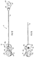
Die Fig. 12 zeigt in perspektivischer Draufsicht ein erstes
Montagehilfsmittel 9 und Fig. 14 ein zweites
Montagehilfsmittel 9' zur genauen Justierung der Clamp-On-Vorrichtung
nach Fig. 2. Die Fig. 13 und 15 zeigen
entsprechende perspektivische teilweise Unteransichten.
Mittels der Montagehilfsmittel 9, 9' können die
Sensoranordnungen 2', 3' von Fig. 2 genau mittig entlang
der beiden Mantelgeraden 11', 11" und damit auch um genau
180° gegeneinander versetzt angeschnallt und in dieser
180°-Position fixiert werden.12 shows a first in a perspective top view
Assembly aids 9 and Fig. 14 a second
Assembly aids 9 'for precise adjustment of the clamp-on device
according to Fig. 2. Figs. 13 and 15 show
corresponding perspective partial bottom views.
By means of the assembly aids 9, 9 '
Sensor arrangements 2 ', 3' of Fig. 2 exactly along the center
of the two
Hierzu dienen zwei möglichst nicht dehnbare Schnüre, z.B.
aus einem dünnen Stahlseil, die im folgenden als ein erstes
und ein zweites Seilstück 91, 91' bezeichnet werden. Von
diesen ist in Fig. 12 das Seilstück 91 und in Fig. 14 das
Seilstück 91' dargestellt.Two non-stretchable cords are used for this, e.g.
from a thin steel cable, which is referred to below as a first
and a second piece of
Ein erstes Ende 92 des Seilstücks 91 von Fig. 12 ist in
einer ersten Seilöse 93 dauernd fixiert, z.B. eingelötet
oder eingepreßt. Die Bohrung 931 der Seilöse 93 hat einen
Durchmesser, der etwas größer als der Durchmesser des
Gewindebolzens 753 von Fig. 3 ist, so daß die Seilöse 93
mit leichtem Drücken darübergeschoben und durch leichtes
Ziehen wieder davon abgenommen werden kann.A
Ein zweites Ende 94 des Seilstücks 91 kann in einer zweiten
Seilöse 95 temporär fixiert werden; somit kann die Länge
des Seilstücks 91 zwischen den beiden Seilösen 93, 95
verstellt werden. A
Die Seilöse 95 umfaßt eine Grundplatte 950, in deren eines
Ende ein Auge 953 mit einer Bohrung 954 eingesetzt ist. Das
Auge 953 ist dicker als die Grundplatte 950. Die Bohrung
954 hat einen Durchmesser, der etwas größer als der
Durchmesser des Gewindebolzens 753 von Fig. 3 ist, so daß
die Seilöse 95 mit leichtem Drücken darübergeschoben und
durch leichtes Ziehen wieder davon abgenommen werden kann.The
Das Ende 94 des Seilstücks 91 läßt sich mittels eines
Klemmstücks 951 durch Eindrehen einer Schraube 952 in die
Grundplatte 950 fixieren. Das Klemmstück 951 befindet sich
unter dem Kopf der Schraube 952.The
Ein erstes Ende 92' des Seilstücks 91' von Fig. 14 ist in einer ersten Seilöse 93' dauernd fixiert, z.B. eingelötet oder eingepreßt. Die Bohrung 931' der Seilöse 93' hat einen Durchmesser, der etwas größer als der Durchmesser des Gewindebolzens 753 von Fig. 3 ist, so daß die Seilöse 93' mit leichtem Drücken darübergeschoben und durch leichtes Ziehen wieder davon abgenommen werden kann.A first end 92 'of the rope piece 91' of FIG. 14 is shown in FIG a first eyelet 93 'permanently fixed, e.g. soldered or pressed. The bore 931 'of the eyelet 93' has one Diameter slightly larger than the diameter of the 3 is such that the cable eyelet 93 ' pushed over with a light push and lightly Pull can be taken off again.
Ein zweites Ende 94' des Seilstücks 91' kann in einer
zweiten Seilöse 95' temporär fixiert werden; somit kann die
Länge des Seilstücks 91 zwischen den beiden Seilösen 93',
95' verstellt werden.A second end 94 'of the rope piece 91' can be in one
second rope eyelet 95 'can be temporarily fixed; thus the
Length of the
Die Seilöse 95' umfaßt eine Grundplatte 950', in deren
eines Ende ein Auge 953' mit einer Bohrung 954' eingesetzt
ist. Das Auge 953' ist dicker als die Grundplatte 950'. Die
Bohrung 954' hat einen Durchmesser, der etwas größer als
der Durchmesser des Gewindebolzens 753 von Fig. 3 ist, so
daß die Seilöse 95' mit leichtem Drücken darübergeschoben
und durch leichtes Ziehen wieder davon abgenommen werden
kann. The rope eyelet 95 'comprises a base plate 950', in the
an eye 953 'is inserted at one end with a bore 954'
is. The eye 953 'is thicker than the base plate 950'. The
Bore 954 'has a diameter that is slightly larger than
3 is the diameter of the threaded
Das Ende 94' des Seilstücks 91' läßt sich mittels eines Klemmstücks 951' durch Eindrehen einer Schraube 952' in die Grundplatte 950' fixieren. Das Klemmstück 951' befindet sich unter dem Kopf der Schraube 952'.The end 94 'of the rope piece 91' can be by means of a Clamping piece 951 'by screwing a screw 952' into the Secure base plate 950 '. The clamp 951 'is located under the head of screw 952 '.
Vor dem Justieren und Fixieren der Sensoranordnungen 2', 3'
von Fig. 2 auf einer Rohrleitung einer gegebenen Nennweite
wird die jeweilige Länge L der Seilstücke 91, 91',
gerechnet von der Achse der Bohrung 931 bzw. 931' der
Seilöse 93 bzw. 93' bis zur Achse der Bohrung 954 bzw. 954'
der Seilöse 94 bzw. 94', anhand der folgenden Formel
berechnet:
In dieser Formel sind:
- U
- der Umfang der Rohrleitung 1' und
- A
- der Abstand zwischen
den Achsen 701 der beiden Spannvorrichtungen 70 der Sensoranordnungen 2', 3'.
- U
- the scope of the pipeline 1 'and
- A
- the distance between the
axes 701 of the twoclamping devices 70 of the sensor arrangements 2 ', 3'.
Der genaue Wert des Abstandes A wird für die Zwecke der Erfindung als im konkreten Anwendungsfall bereits ermittelt und somit als bekannt vorausgesetzt. An sich ist der Abstand A von mehreren Parametern abhängig, nämlich z.B. von dem Durchmesser der Rohrleitung 1', deren Wandstärke, der Art des zu messenden Fluids, dessen Temperatur etc.The exact value of the distance A is used for the purposes of Invention already determined as in the specific application and therefore assumed to be known. In itself it is Distance A depends on several parameters, namely e.g. the diameter of the pipeline 1 ', its wall thickness, the type of fluid to be measured, its temperature etc.
Diese Parameter sind von vornherein bekannt oder meß-/ bestimmbar und können daher z.B. mittels eines Mikroprozessors, in den sie eingegeben werden, zu dem für einen konkreten Anwendungsfall gehörenden Wert des Abstandes A verarbeitet werden.These parameters are known from the outset or determinable and can therefore e.g. by means of a Microprocessor into which they are entered to the for value of a specific application Distance A can be processed.
So können z.B. die Wandstärke der Rohrleitung 1' und die
Art des Fluids mittels bekannter Ultraschall-Meßverfahren
ermittelt werden. Entsprechende Meßanordnungen können
Bestandteil der Clamp-On-Vorrichtung 10, 10' sein. For example, the wall thickness of the pipeline 1 'and the
Type of fluid using known ultrasonic measuring methods
be determined. Corresponding measuring arrangements can
Be part of the clamp-on
Nachdem der konkrete Wert der Länge L berechnet ist, werden
die beiden Seilstücke 91, 91' auf diesen Wert eingestellt,
indem das Ende 94 bzw. 94' auf der Grundplatte 950 bzw.
950' mittels der Schraube 952 bzw. 952' und des Klemmstücks
952 bzw. 952' festgeklemmt wird.After the concrete value of length L is calculated,
the two pieces of
Nun wird der eine, z.B. der zur Sensoranordnung 2'
gehörende, Spanner 75 wie oben beschrieben auf der
Rohrleitung 1' mittels des Fixierbandes 4' aufgeschnallt
und fixiert. Über den Gewindebolzen 753 des Spanners 75
werden die Seilöse 93 des Seilstücks 91 und darüber die
Seilöse 93' des Seilstücks 91' bis zum unteren Ende des
Gewindebolzens 753 geschoben.Now the one, e.g. to the sensor arrangement 2 '
belonging,
Dann wird der andere, zur Sensoranordnung 3' gehörende
Spanner mittels des Fixierbandes 5' vor-aufgeschnallt. Über
den zugehörigen Gewindebolzen 753 werden die Seilöse 95 des
Seilstücks 91 und darüber die Seilöse 95' des Seilstücks
91' bis zum unteren Ende dieses Gewindebolzens geschoben.Then the other, belonging to the sensor arrangement 3 '
Pre-strapped with the
Beim Anbringen der beiden Seilstücke 91, 91' ist darauf zu
achten, daß das eine Seilstück auf der einen Seite und das
andere Seilstück auf der anderen Seite um die Rohrleitung
1' herum vom einen zum anderen Gewindebolzen läuft.When attaching the two pieces of
Das Fixierband 5' wird nun so lange in Achsrichtung der
Rohrleitung 1' verschoben und zugleich in Richtung von
deren Umfang so lange verdreht, bis beide Seilstücke 91,
91' gespannt sind. In diesem Fall sind die
Sensoranordnungen 2', 2' justiert und um genau 180°
gegeneinander verdreht.The fixing tape 5 'is now in the axial direction
Pipeline 1 'moved and at the same time in the direction of
whose circumference is twisted until both
Daraufhin werden die Fixierbänder 4', 5' endgültig gespannt
und die Sensoranordnungen 2', 3' durch Anziehen der Muttern
70 festgeschraubt und somit endgültig aufgeschnallt. Danach
werden die beiden Schrauben 952, 952' und somit die
Klemmstücke 951, 951' gelöst, so daß die beiden Seilstücke
91, 91' von den Seilösen 95, 95' getrennt werden können.
Schließlich werden die Seilösen 93, 93', 95, 95' vom
jeweiligen Gewindebolzen entfernt.Then the fixing straps 4 ', 5' are finally tensioned
and the sensor arrangements 2 ', 3' by tightening the nuts
70 screwed down and thus finally strapped on. After that
the two
Claims (4)
Priority Applications (1)
| Application Number | Priority Date | Filing Date | Title |
|---|---|---|---|
| EP99113687.0A EP0974815B1 (en) | 1998-07-22 | 1999-07-15 | Clamp-on ultrasonic sensor arrangement |
Applications Claiming Priority (3)
| Application Number | Priority Date | Filing Date | Title |
|---|---|---|---|
| EP98113670 | 1998-07-22 | ||
| EP98113670 | 1998-07-22 | ||
| EP99113687.0A EP0974815B1 (en) | 1998-07-22 | 1999-07-15 | Clamp-on ultrasonic sensor arrangement |
Publications (2)
| Publication Number | Publication Date |
|---|---|
| EP0974815A1 true EP0974815A1 (en) | 2000-01-26 |
| EP0974815B1 EP0974815B1 (en) | 2015-09-16 |
Family
ID=26149463
Family Applications (1)
| Application Number | Title | Priority Date | Filing Date |
|---|---|---|---|
| EP99113687.0A Expired - Lifetime EP0974815B1 (en) | 1998-07-22 | 1999-07-15 | Clamp-on ultrasonic sensor arrangement |
Country Status (1)
| Country | Link |
|---|---|
| EP (1) | EP0974815B1 (en) |
Cited By (12)
| Publication number | Priority date | Publication date | Assignee | Title |
|---|---|---|---|---|
| EP1396707A1 (en) * | 2001-06-13 | 2004-03-10 | Fuji Electric Co., Ltd. | Ultrasonic flow rate measurement instrument |
| DE10348676A1 (en) * | 2003-10-15 | 2005-05-12 | Flowtec Ag | Device for determining and / or monitoring the volume and / or mass flow of a medium in a pipeline |
| DE102005052550B3 (en) * | 2005-11-02 | 2007-02-08 | Krohne Ag | Clamp-on ultrasound flow-through measuring device comprises a guiding frame fixed to a fixing unit so that it moves away from or toward a tube and pivots along a pivoting axis |
| DE102006015217A1 (en) * | 2006-03-30 | 2007-10-11 | Krohne Ag | Clamp-on ultrasonic flow measuring device for integration in pipeline system, has fixing device for moving measuring transducer towards and/or away from conduit and for fixation at and/or detachment from guide frame |
| DE102007019610A1 (en) * | 2007-04-24 | 2008-10-30 | Endress + Hauser Flowtec Ag | Device for attaching a measuring or display unit to an object |
| DE102007019689A1 (en) | 2007-04-24 | 2008-10-30 | Endress + Hauser Flowtec Ag | Device for determining and / or monitoring the volume and / or mass flow of a medium |
| DE102007023802A1 (en) * | 2007-05-21 | 2008-11-27 | Endress + Hauser Flowtec Ag | Clamp on flow meter for fixing in pipe line, has multiple modular shaped components, which are combined in different arrangements and two different types of clamp on flow meters are realized |
| WO2009130029A1 (en) * | 2008-04-24 | 2009-10-29 | Eni S.P.A. | Method for the elastic installation of detection devices on pipelines and suitable device therefor |
| CN102914334A (en) * | 2012-09-29 | 2013-02-06 | 郑州光力科技股份有限公司 | Inserted type ultrasonic gas flowmeter |
| GB2519643A (en) * | 2014-08-23 | 2015-04-29 | Kamran Iqbal | Flow monitor |
| DE102006062705B4 (en) * | 2006-03-30 | 2015-07-30 | Krohne Ag | ultrasonic flowmeter |
| DE102022103953A1 (en) | 2022-02-18 | 2023-08-24 | Endress+Hauser Flowtec Ag | Ultrasonic transducer and clamp-on ultrasonic measuring device |
Citations (3)
| Publication number | Priority date | Publication date | Assignee | Title |
|---|---|---|---|---|
| EP0198731A2 (en) * | 1985-03-15 | 1986-10-22 | Framatome | Ultrasonic-wave transducer to get in contact with a high-temperature wall, and its use |
| EP0334795A2 (en) * | 1988-03-23 | 1989-09-27 | IRD MECHANALYSIS, Inc. | Vibration transducer mounting |
| US5131278A (en) * | 1989-06-13 | 1992-07-21 | Joseph Baumoel | Mounting structure for transducers with sonic-energy absorbing means |
-
1999
- 1999-07-15 EP EP99113687.0A patent/EP0974815B1/en not_active Expired - Lifetime
Patent Citations (3)
| Publication number | Priority date | Publication date | Assignee | Title |
|---|---|---|---|---|
| EP0198731A2 (en) * | 1985-03-15 | 1986-10-22 | Framatome | Ultrasonic-wave transducer to get in contact with a high-temperature wall, and its use |
| EP0334795A2 (en) * | 1988-03-23 | 1989-09-27 | IRD MECHANALYSIS, Inc. | Vibration transducer mounting |
| US5131278A (en) * | 1989-06-13 | 1992-07-21 | Joseph Baumoel | Mounting structure for transducers with sonic-energy absorbing means |
Cited By (20)
| Publication number | Priority date | Publication date | Assignee | Title |
|---|---|---|---|---|
| EP1396707A4 (en) * | 2001-06-13 | 2006-01-25 | Fuji Electric Co Ltd | Ultrasonic flow rate measurement instrument |
| EP1396707A1 (en) * | 2001-06-13 | 2004-03-10 | Fuji Electric Co., Ltd. | Ultrasonic flow rate measurement instrument |
| US7373839B2 (en) | 2003-10-15 | 2008-05-20 | Endress + Hauser Flowtec Ag | Apparatus for determining and/or monitoring volume- and/or mass-flow of a medium in a pipeline |
| DE10348676A1 (en) * | 2003-10-15 | 2005-05-12 | Flowtec Ag | Device for determining and / or monitoring the volume and / or mass flow of a medium in a pipeline |
| DE102005052550B3 (en) * | 2005-11-02 | 2007-02-08 | Krohne Ag | Clamp-on ultrasound flow-through measuring device comprises a guiding frame fixed to a fixing unit so that it moves away from or toward a tube and pivots along a pivoting axis |
| US7458279B2 (en) | 2005-11-02 | 2008-12-02 | Krohne Ag | Clamp-on measuring device |
| DE102006015217B4 (en) * | 2006-03-30 | 2008-01-24 | Krohne Ag | ultrasonic flowmeter |
| DE102006015217A1 (en) * | 2006-03-30 | 2007-10-11 | Krohne Ag | Clamp-on ultrasonic flow measuring device for integration in pipeline system, has fixing device for moving measuring transducer towards and/or away from conduit and for fixation at and/or detachment from guide frame |
| DE102006062705B4 (en) * | 2006-03-30 | 2015-07-30 | Krohne Ag | ultrasonic flowmeter |
| DE102007019689A1 (en) | 2007-04-24 | 2008-10-30 | Endress + Hauser Flowtec Ag | Device for determining and / or monitoring the volume and / or mass flow of a medium |
| US8267365B2 (en) | 2007-04-24 | 2012-09-18 | Endress + Hauser Flowtec Ag | Apparatus for securing a measuring or display unit on an object |
| DE102007019610A1 (en) * | 2007-04-24 | 2008-10-30 | Endress + Hauser Flowtec Ag | Device for attaching a measuring or display unit to an object |
| DE102007023802A1 (en) * | 2007-05-21 | 2008-11-27 | Endress + Hauser Flowtec Ag | Clamp on flow meter for fixing in pipe line, has multiple modular shaped components, which are combined in different arrangements and two different types of clamp on flow meters are realized |
| EA021243B1 (en) * | 2008-04-24 | 2015-05-29 | Эни С.П.А. | Method for the elastic installation of detection devices on pipelines and suitable device therefor |
| WO2009130029A1 (en) * | 2008-04-24 | 2009-10-29 | Eni S.P.A. | Method for the elastic installation of detection devices on pipelines and suitable device therefor |
| US8549938B2 (en) | 2008-04-24 | 2013-10-08 | Eni S.P.A. | Method for the elastic installation of detection devices on pipelines and suitable device therefor |
| CN102914334A (en) * | 2012-09-29 | 2013-02-06 | 郑州光力科技股份有限公司 | Inserted type ultrasonic gas flowmeter |
| CN102914334B (en) * | 2012-09-29 | 2015-04-29 | 郑州光力科技股份有限公司 | Inserted type ultrasonic gas flowmeter |
| GB2519643A (en) * | 2014-08-23 | 2015-04-29 | Kamran Iqbal | Flow monitor |
| DE102022103953A1 (en) | 2022-02-18 | 2023-08-24 | Endress+Hauser Flowtec Ag | Ultrasonic transducer and clamp-on ultrasonic measuring device |
Also Published As
| Publication number | Publication date |
|---|---|
| EP0974815B1 (en) | 2015-09-16 |
Similar Documents
| Publication | Publication Date | Title |
|---|---|---|
| DE2743394C3 (en) | Device for attaching a sonic or ultrasonic transducer intended for level measurement to a container | |
| EP0974815B1 (en) | Clamp-on ultrasonic sensor arrangement | |
| EP1780518B1 (en) | Fastening device for fastening a clamp-on flow measuring apparatus | |
| EP0615611B1 (en) | Device for securing a housing | |
| DE2946826A1 (en) | FLOW MONITOR FOR LIQUID OR GASEOUS MEDIA | |
| DE2022079A1 (en) | Fastening element with voltage indicator and method and device for measuring it | |
| DE10230568B4 (en) | Device and series of devices | |
| EP0402460B1 (en) | Electromagnetic flow meter | |
| EP0717267A1 (en) | Fastening device for a sensor | |
| DE60314209T2 (en) | Method and device for avoiding internal air gaps in housings of magnetic sensors | |
| DE4444831C2 (en) | Pressure sensor | |
| WO2020083805A1 (en) | Measurement device for determining the flow of a fluid flowing through a pipe section | |
| DE3928733C2 (en) | Pressure gauge with helically wound Bourdon tube coils | |
| EP1278999A1 (en) | Measuring sensor | |
| DE3038957C2 (en) | Add-on housing for fastening a device arranged in a housing | |
| DE3416109A1 (en) | Device for the pivotable and detachable connection of two pipelines which run at an angle with respect to one another | |
| DE202013005259U1 (en) | Detection device | |
| EP0327103A2 (en) | Vortex frequency flow rate meter | |
| EP0977018A1 (en) | Electrode arrangement for magneto-inductive flow sensors | |
| EP1143230B1 (en) | Strain and force measuring device | |
| DE4007279C2 (en) | Connection device for single-nozzle gas meter | |
| DE3342797T1 (en) | Measuring unit for measuring the gas throughput through a line and a measuring device that can be built into such a measuring unit | |
| DE102011014225A1 (en) | Flow meter i.e. magnetic-inductive flow meter, for e.g. monitoring flow rate of medium in pipeline, has seal whose height is varied over its entire radial extension so that height is adapted to planes of sealing contour | |
| DE102008064455A1 (en) | Monitoring device for monitoring a flowable medium | |
| DE4103601C1 (en) | Torque wrench for fasteners - has calibrated spring tube to indicate torque applied by wrench |
Legal Events
| Date | Code | Title | Description |
|---|---|---|---|
| PUAI | Public reference made under article 153(3) epc to a published international application that has entered the european phase |
Free format text: ORIGINAL CODE: 0009012 |
|
| AK | Designated contracting states |
Kind code of ref document: A1 Designated state(s): AT BE CH CY DE DK ES FI FR GB GR IE IT LI LU MC NL PT SE |
|
| AX | Request for extension of the european patent |
Free format text: AL;LT;LV;MK;RO;SI |
|
| 17P | Request for examination filed |
Effective date: 20000211 |
|
| D17P | Request for examination filed (deleted) | ||
| R17P | Request for examination filed (corrected) |
Effective date: 20000221 |
|
| AKX | Designation fees paid |
Free format text: AT BE CH CY DE DK ES FI FR GB GR IE IT LI LU MC NL PT SE |
|
| 17Q | First examination report despatched |
Effective date: 20071024 |
|
| GRAP | Despatch of communication of intention to grant a patent |
Free format text: ORIGINAL CODE: EPIDOSNIGR1 |
|
| INTG | Intention to grant announced |
Effective date: 20150421 |
|
| GRAS | Grant fee paid |
Free format text: ORIGINAL CODE: EPIDOSNIGR3 |
|
| GRAA | (expected) grant |
Free format text: ORIGINAL CODE: 0009210 |
|
| AK | Designated contracting states |
Kind code of ref document: B1 Designated state(s): AT BE CH CY DE DK ES FI FR GB GR IE IT LI LU MC NL PT SE |
|
| REG | Reference to a national code |
Ref country code: GB Ref legal event code: FG4D Free format text: NOT ENGLISH |
|
| REG | Reference to a national code |
Ref country code: CH Ref legal event code: EP |
|
| REG | Reference to a national code |
Ref country code: IE Ref legal event code: FG4D Free format text: LANGUAGE OF EP DOCUMENT: GERMAN |
|
| REG | Reference to a national code |
Ref country code: AT Ref legal event code: REF Ref document number: 750154 Country of ref document: AT Kind code of ref document: T Effective date: 20151015 |
|
| REG | Reference to a national code |
Ref country code: DE Ref legal event code: R096 Ref document number: 59915435 Country of ref document: DE |
|
| REG | Reference to a national code |
Ref country code: NL Ref legal event code: MP Effective date: 20150916 |
|
| PG25 | Lapsed in a contracting state [announced via postgrant information from national office to epo] |
Ref country code: GR Free format text: LAPSE BECAUSE OF FAILURE TO SUBMIT A TRANSLATION OF THE DESCRIPTION OR TO PAY THE FEE WITHIN THE PRESCRIBED TIME-LIMIT Effective date: 20151217 Ref country code: FI Free format text: LAPSE BECAUSE OF FAILURE TO SUBMIT A TRANSLATION OF THE DESCRIPTION OR TO PAY THE FEE WITHIN THE PRESCRIBED TIME-LIMIT Effective date: 20150916 |
|
| PG25 | Lapsed in a contracting state [announced via postgrant information from national office to epo] |
Ref country code: SE Free format text: LAPSE BECAUSE OF FAILURE TO SUBMIT A TRANSLATION OF THE DESCRIPTION OR TO PAY THE FEE WITHIN THE PRESCRIBED TIME-LIMIT Effective date: 20150916 |
|
| PG25 | Lapsed in a contracting state [announced via postgrant information from national office to epo] |
Ref country code: NL Free format text: LAPSE BECAUSE OF FAILURE TO SUBMIT A TRANSLATION OF THE DESCRIPTION OR TO PAY THE FEE WITHIN THE PRESCRIBED TIME-LIMIT Effective date: 20150916 |
|
| PG25 | Lapsed in a contracting state [announced via postgrant information from national office to epo] |
Ref country code: ES Free format text: LAPSE BECAUSE OF FAILURE TO SUBMIT A TRANSLATION OF THE DESCRIPTION OR TO PAY THE FEE WITHIN THE PRESCRIBED TIME-LIMIT Effective date: 20150916 |
|
| PG25 | Lapsed in a contracting state [announced via postgrant information from national office to epo] |
Ref country code: PT Free format text: LAPSE BECAUSE OF FAILURE TO SUBMIT A TRANSLATION OF THE DESCRIPTION OR TO PAY THE FEE WITHIN THE PRESCRIBED TIME-LIMIT Effective date: 20160118 |
|
| REG | Reference to a national code |
Ref country code: DE Ref legal event code: R097 Ref document number: 59915435 Country of ref document: DE |
|
| PLBE | No opposition filed within time limit |
Free format text: ORIGINAL CODE: 0009261 |
|
| STAA | Information on the status of an ep patent application or granted ep patent |
Free format text: STATUS: NO OPPOSITION FILED WITHIN TIME LIMIT |
|
| 26N | No opposition filed |
Effective date: 20160617 |
|
| PG25 | Lapsed in a contracting state [announced via postgrant information from national office to epo] |
Ref country code: DK Free format text: LAPSE BECAUSE OF FAILURE TO SUBMIT A TRANSLATION OF THE DESCRIPTION OR TO PAY THE FEE WITHIN THE PRESCRIBED TIME-LIMIT Effective date: 20150916 |
|
| PGFP | Annual fee paid to national office [announced via postgrant information from national office to epo] |
Ref country code: DE Payment date: 20160722 Year of fee payment: 18 |
|
| PG25 | Lapsed in a contracting state [announced via postgrant information from national office to epo] |
Ref country code: BE Free format text: LAPSE BECAUSE OF NON-PAYMENT OF DUE FEES Effective date: 20160731 |
|
| REG | Reference to a national code |
Ref country code: CH Ref legal event code: PL |
|
| GBPC | Gb: european patent ceased through non-payment of renewal fee |
Effective date: 20160715 |
|
| PG25 | Lapsed in a contracting state [announced via postgrant information from national office to epo] |
Ref country code: MC Free format text: LAPSE BECAUSE OF FAILURE TO SUBMIT A TRANSLATION OF THE DESCRIPTION OR TO PAY THE FEE WITHIN THE PRESCRIBED TIME-LIMIT Effective date: 20150916 |
|
| PG25 | Lapsed in a contracting state [announced via postgrant information from national office to epo] |
Ref country code: FR Free format text: LAPSE BECAUSE OF NON-PAYMENT OF DUE FEES Effective date: 20160801 Ref country code: LI Free format text: LAPSE BECAUSE OF NON-PAYMENT OF DUE FEES Effective date: 20160731 Ref country code: CH Free format text: LAPSE BECAUSE OF NON-PAYMENT OF DUE FEES Effective date: 20160731 |
|
| REG | Reference to a national code |
Ref country code: FR Ref legal event code: ST Effective date: 20170331 |
|
| REG | Reference to a national code |
Ref country code: IE Ref legal event code: MM4A |
|
| PG25 | Lapsed in a contracting state [announced via postgrant information from national office to epo] |
Ref country code: GB Free format text: LAPSE BECAUSE OF NON-PAYMENT OF DUE FEES Effective date: 20160715 |
|
| PG25 | Lapsed in a contracting state [announced via postgrant information from national office to epo] |
Ref country code: IE Free format text: LAPSE BECAUSE OF NON-PAYMENT OF DUE FEES Effective date: 20160715 |
|
| PG25 | Lapsed in a contracting state [announced via postgrant information from national office to epo] |
Ref country code: LU Free format text: LAPSE BECAUSE OF NON-PAYMENT OF DUE FEES Effective date: 20160715 Ref country code: IT Free format text: LAPSE BECAUSE OF NON-PAYMENT OF DUE FEES Effective date: 20160715 |
|
| REG | Reference to a national code |
Ref country code: AT Ref legal event code: MM01 Ref document number: 750154 Country of ref document: AT Kind code of ref document: T Effective date: 20160715 |
|
| PG25 | Lapsed in a contracting state [announced via postgrant information from national office to epo] |
Ref country code: AT Free format text: LAPSE BECAUSE OF NON-PAYMENT OF DUE FEES Effective date: 20160715 |
|
| REG | Reference to a national code |
Ref country code: DE Ref legal event code: R119 Ref document number: 59915435 Country of ref document: DE |
|
| PG25 | Lapsed in a contracting state [announced via postgrant information from national office to epo] |
Ref country code: DE Free format text: LAPSE BECAUSE OF NON-PAYMENT OF DUE FEES Effective date: 20180201 |
|
| PG25 | Lapsed in a contracting state [announced via postgrant information from national office to epo] |
Ref country code: CY Free format text: LAPSE BECAUSE OF FAILURE TO SUBMIT A TRANSLATION OF THE DESCRIPTION OR TO PAY THE FEE WITHIN THE PRESCRIBED TIME-LIMIT Effective date: 20150916 |