EP0717267A1 - Fastening device for a sensor - Google Patents
Fastening device for a sensor Download PDFInfo
- Publication number
- EP0717267A1 EP0717267A1 EP95118808A EP95118808A EP0717267A1 EP 0717267 A1 EP0717267 A1 EP 0717267A1 EP 95118808 A EP95118808 A EP 95118808A EP 95118808 A EP95118808 A EP 95118808A EP 0717267 A1 EP0717267 A1 EP 0717267A1
- Authority
- EP
- European Patent Office
- Prior art keywords
- sensor
- retaining ring
- ring
- shoulder
- plate spring
- Prior art date
- Legal status (The legal status is an assumption and is not a legal conclusion. Google has not performed a legal analysis and makes no representation as to the accuracy of the status listed.)
- Granted
Links
Images
Classifications
-
- G—PHYSICS
- G01—MEASURING; TESTING
- G01D—MEASURING NOT SPECIALLY ADAPTED FOR A SPECIFIC VARIABLE; ARRANGEMENTS FOR MEASURING TWO OR MORE VARIABLES NOT COVERED IN A SINGLE OTHER SUBCLASS; TARIFF METERING APPARATUS; MEASURING OR TESTING NOT OTHERWISE PROVIDED FOR
- G01D11/00—Component parts of measuring arrangements not specially adapted for a specific variable
- G01D11/30—Supports specially adapted for an instrument; Supports specially adapted for a set of instruments
-
- B—PERFORMING OPERATIONS; TRANSPORTING
- B60—VEHICLES IN GENERAL
- B60C—VEHICLE TYRES; TYRE INFLATION; TYRE CHANGING; CONNECTING VALVES TO INFLATABLE ELASTIC BODIES IN GENERAL; DEVICES OR ARRANGEMENTS RELATED TO TYRES
- B60C23/00—Devices for measuring, signalling, controlling, or distributing tyre pressure or temperature, specially adapted for mounting on vehicles; Arrangement of tyre inflating devices on vehicles, e.g. of pumps or of tanks; Tyre cooling arrangements
- B60C23/02—Signalling devices actuated by tyre pressure
- B60C23/04—Signalling devices actuated by tyre pressure mounted on the wheel or tyre
-
- Y—GENERAL TAGGING OF NEW TECHNOLOGICAL DEVELOPMENTS; GENERAL TAGGING OF CROSS-SECTIONAL TECHNOLOGIES SPANNING OVER SEVERAL SECTIONS OF THE IPC; TECHNICAL SUBJECTS COVERED BY FORMER USPC CROSS-REFERENCE ART COLLECTIONS [XRACs] AND DIGESTS
- Y10—TECHNICAL SUBJECTS COVERED BY FORMER USPC
- Y10S—TECHNICAL SUBJECTS COVERED BY FORMER USPC CROSS-REFERENCE ART COLLECTIONS [XRACs] AND DIGESTS
- Y10S411/00—Expanded, threaded, driven, headed, tool-deformed, or locked-threaded fastener
- Y10S411/999—Expanded, threaded, driven, headed, tool-deformed, or locked-threaded fastener with retainer, e.g. tether
Definitions
- the invention relates to a mounting arrangement for a sensor, the type explained in the preamble of claim 1.
- a sensor that can be used in an opening in a wall is sealed by an O-ring and a plate spring-like retaining ring and is easily detachably held in its installed position.
- a fine adjustment of the sensor position is not provided and, in addition, a retaining ring in the form of two annular disk halves must be arranged in a receiving groove of the sensor to hold the sensor in addition to the plate spring-like retaining ring. To assemble and disassemble the sensor, it must be accessible from both sides of the wall.
- a securing element for a screw nut which can be placed on a threaded bolt is known and consists of a resilient sheet metal ring, the inner circumference of which forms a thread which is interrupted at one point.
- the known securing element does not allow a simple axial pressing in of the component to be fastened and is also not able to seal this component to be fastened against the housing receiving it.
- the object of the invention is to improve a mounting arrangement for a sensor of the type explained in the preamble of claim 1 in such a way that a subsequent fine adjustment of the sensor is made possible with reliable sealing and, moreover, disassembly of the sensor is only possible from one side of the wall is.
- this object is achieved in that, in the case of a fastening arrangement for a sensor of the type explained in the preamble of patent claim 1, the measures indicated in the characterizing part of patent claim 1 are provided.
- the plate spring-like retaining ring with a cylindrical outer circumference can be inserted in a clamping manner in an enlarged shoulder of the opening in the wall, the plate spring-like retaining ring sealingly bracing the O-ring with respect to the shoulder of the shoulder and the plate spring-like retaining ring being provided with a thread on its inner periphery , which jams in a clamped manner on the cylindrical shaft of the sensor, enables simple mounting of the sensor by simply axially inserting it with a predetermined force while deforming the plate spring-like retaining ring, whereupon fine adjustment is possible by rotating the sensor and disassembly of the sensor is also possible possible simply by unscrewing it along the thread.
- a sensor 1 is used in a wall 2 in a housing.
- the wall 2 has a bore 3 with an enlarged bore section 4 and a shoulder 5.
- the sensor 1 has a cylindrical shaft 6 with an enlarged shoulder 7, which is followed by a further enlarged handle 8.
- the sensor 1 is inserted into the bore 3 of the housing 2 in order to use its shaft 6 to record measured or numerical values in the housing, which are led to the outside via a line 9 to a processing unit (not shown).
- an O-ring 10 and a plate spring-like retaining ring 11 are arranged between the shoulder 5 in the bore 3 and the extended shoulder 7 of the sensor 1 protruding therein.
- the plate-spring-like retaining ring 11 is conically deformed downward and has a cylindrical outer circumference 12 and an inner circumference 13 designed as a thread, the inner circumference 13 being interrupted by a recess 14 at least at one point, preferably at four points, to ensure the thread function.
- the assembly of the fastening arrangement according to the invention is explained below:
- the disc spring-like retaining ring 11 with its inner circumference 13 is placed in a slightly clamping manner on the shaft 6 of the sensor 1 and then the O-ring 10 is pushed on. Subsequently, the sensor 1 is inserted into the bore 3 in the housing 2 and is simply pressed axially into it.
- the outer circumference 12 of the plate spring-like retaining ring 11 is designed so that it can only be inserted by clamping into the enlarged section 4 of the bore 3.
- the disk spring-like retaining ring 11, which clamps with its outer circumference 12 at section 4 is deformed more conically and thereby compresses the O-ring 10 with respect to the shoulder 5, as a result of which this is compared both to the outer circumference of the extension 4 and to the cylindrical shaft 6 seals.
- the sensor 1 is now held in the housing 2 by the support of the plate spring-like retaining ring 11, which is resilient both inwards (shaft 6) and outwards (section 4).
- the sensor 1 can be completely unscrewed for complete disassembly.
- the housing 2 and the sensor 1 may consist of light metals makes it easy to see that the corresponding resilient catches of the plate spring-like retaining ring made of spring steel enable the sensor to be held securely.
Landscapes
- Engineering & Computer Science (AREA)
- Mechanical Engineering (AREA)
- Physics & Mathematics (AREA)
- General Physics & Mathematics (AREA)
- Snaps, Bayonet Connections, Set Pins, And Snap Rings (AREA)
- Details Of Measuring And Other Instruments (AREA)
- Measuring Fluid Pressure (AREA)
Abstract
Bei einer Befestigungsanordnung für einen Sensor (1) der zur Erfassung eines Meß- oder Zahlenwertes über eine Bohrung (3) in einer Wandung (2) eines Gehäuses einsetzbar ist und über einen O-Ring (10) und einen tellerfederartigen Haltering (11) abgedichtet und lösbar gehalten ist, ist der Sensor (1) mit an einer Schulter (7) anliegendem tellerfederartigen Haltering (11) mit zylindrischen Außenumfang (12) in den erweiterten Abschnitt (4) der Bohrung (3) in der Wandung (2) klemmend axial eindrückbar, der O-Ring (10) zwischen der Schulter (7) und dem Absatz (5) axial verspannbar und der Sensor (1) an seinem zylindrischen Schaft (6) über den einen Gewindegang bildenden Innenumfang (13) des tellerfederartigen Halteringes (11) axial fixierbar. <IMAGE>In the case of a mounting arrangement for a sensor (1) which can be used to detect a measured or numerical value via a bore (3) in a wall (2) of a housing and which is sealed by an O-ring (10) and a plate-type retaining ring (11) and is detachably held, the sensor (1) with a plate spring-like retaining ring (11) lying against a shoulder (7) with a cylindrical outer circumference (12) is axially clamping in the enlarged section (4) of the bore (3) in the wall (2) can be pressed in, the O-ring (10) can be clamped axially between the shoulder (7) and the shoulder (5) and the sensor (1) on its cylindrical shaft (6) via the inner circumference (13) of the plate spring-like retaining ring (11 ) axially fixable. <IMAGE>
Description
Die Erfindung bezieht sich auf eine Befestigungsanordnung für einen Sensor, der im Oberbegriff des Patentanspruches 1 erläuterten Art.The invention relates to a mounting arrangement for a sensor, the type explained in the preamble of
Aus der EP-PS 0 414 690 ist eine Befestigungsanordnung für einen Sensor etwa der im Oberbegriff des Patentanspruches 1 erläuterten Art bekannt.From EP-PS 0 414 690 a mounting arrangement for a sensor is known approximately of the type explained in the preamble of
Bei dieser bekannten Befestigungsanordnung wird ein in einer Öffnung einer Wandung einsetzbarer Sensor über einen O-Ring und einen tellerfederartigen Haltering abgedichtet und leicht lösbar in seiner Einbaulage gehalten.In this known fastening arrangement, a sensor that can be used in an opening in a wall is sealed by an O-ring and a plate spring-like retaining ring and is easily detachably held in its installed position.
Bei der bekannten Befestigungsanordnung für einen Sensor ist eine Feineinstellung der Sensorlage nicht vorgesehen und darüber hinaus muß zum Halten des Sensors zusätzlich zum tellerfederartigen Haltering ein Sicherungsring in Form von zwei Ringscheibenhälften in einer Aufnahmenut des Sensors angeordnet sein. Zur Montage und Demontage des Sensors muß dieser von beiden Seiten der Wandung zugänglich sein.In the known mounting arrangement for a sensor, a fine adjustment of the sensor position is not provided and, in addition, a retaining ring in the form of two annular disk halves must be arranged in a receiving groove of the sensor to hold the sensor in addition to the plate spring-like retaining ring. To assemble and disassemble the sensor, it must be accessible from both sides of the wall.
Aus der DE-PS 30 09 716 ist ein Sicherungselement für eine auf einem Gewindebolzen aufsetzbare Schraubenmutter bekannt, das aus einem federnden Blechring besteht, dessen Innenumfang einen Gewindegang bildet, der an einer Stelle unterbrochen ist.From DE-PS 30 09 716 a securing element for a screw nut which can be placed on a threaded bolt is known and consists of a resilient sheet metal ring, the inner circumference of which forms a thread which is interrupted at one point.
Das bekannte Sicherungselement ermöglicht jedoch nicht ein einfaches axiales Eindrücken des zu befestigenden Bauteiles und ist auch nicht in der Lage, dieses zu befestigende Bauteil gegenüber dem es aufnehmenden Gehäuse abzudichten.However, the known securing element does not allow a simple axial pressing in of the component to be fastened and is also not able to seal this component to be fastened against the housing receiving it.
Die Aufgabe der Erfindung ist es, eine Befestigungsanordnung für einen Sensor der im Oberbegriff des Patentanspruches 1 erläuterten Art derart zu verbessern, daß bei zuverlässiger Abdichtung eine nachträgliche Feineinstellung des Sensors ermöglicht wird und darüber hinaus eine Demontage des Sensors nur von einer Seite der Wandung her möglich ist.The object of the invention is to improve a mounting arrangement for a sensor of the type explained in the preamble of
Gemäß der Erfindung wird diese Aufgabe gelöst, indem bei einer Befestigungsanordnung für einen Sensor der im Oberbegriff des Patentanspruches 1 erläuterten Art, die im Kennzeichenteil des Patentanspruches 1 aufgezeigten Maßnahmen vorgesehen werden.According to the invention, this object is achieved in that, in the case of a fastening arrangement for a sensor of the type explained in the preamble of
Dadurch, daß der tellerfederartige Haltering mit einem zylindrischen Außenumfang in einem erweiterten Absatz der Öffnung in der Wandung klemmend einsetzbar ist, wobei der tellerfederartige Haltering den O-Ring gegenüber der Schulter des Absatzes abdichtend verspannt und der tellerfederartige Haltering an seinem Innenumfang mit einem Gewindegang versehen ist, der sich klemmend am zylindrischen Schaft des Sensors verkantet, wird eine einfache Montage des Sensors durch einfaches axiales Einstecken mit einer vorbestimmten Kraft unter Verformung des tellerfederartigen Halteringes ermöglicht, worauf durch Drehen des Sensors noch eine Feineinstellung möglich wird und eine Demontage des Sensors ist in ebenso einfacher Weise durch ein Herausdrehen entlang des Gewindeganges möglich.Characterized in that the plate spring-like retaining ring with a cylindrical outer circumference can be inserted in a clamping manner in an enlarged shoulder of the opening in the wall, the plate spring-like retaining ring sealingly bracing the O-ring with respect to the shoulder of the shoulder and the plate spring-like retaining ring being provided with a thread on its inner periphery , which jams in a clamped manner on the cylindrical shaft of the sensor, enables simple mounting of the sensor by simply axially inserting it with a predetermined force while deforming the plate spring-like retaining ring, whereupon fine adjustment is possible by rotating the sensor and disassembly of the sensor is also possible possible simply by unscrewing it along the thread.
Die Erfindung wird anhand einer in der Zeichnung gezeigten Ausführungsform näher erläutert. Es zeigt:
- Fig. 1
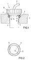
- einen vertikalen Schnitt entlang der Achse des Sensors in seiner Einbaulage in einer Wandung;
- Fig. 2
- eine Draufsicht auf den erfindungsgemäßen tellerförmigen Haltering zum Festlegen des Sensors.
- Fig. 1
- a vertical section along the axis of the sensor in its installed position in a wall;
- Fig. 2
- a plan view of the plate-shaped retaining ring according to the invention for fixing the sensor.
Wie aus Fig. 1 zu ersehen ist, wird ein Sensor 1 in einer Wandung 2 in einem Gehäuse eingesetzt. Die Wandung 2 weist hierzu eine Bohrung 3 mit einem erweiterten Bohrungsabschnitt 4 und einem Absatz 5 auf.As can be seen from Fig. 1, a
Der Sensor 1 weist einen zylindrischen Schaft 6 mit einer erweiterten Schulter 7 auf, an die sich eine nochmals erweiterte Handhabe 8 anschließt. Der Sensor 1 wird in die Bohrung 3 des Gehäuses 2 eingesetzt, um mit seinem Schaft 6 Meß- oder Zahlenwerte im Gehäuse zu erfassen, die nach außen über eine Leitung 9 zu einer Verarbeitungseinheit (nicht gezeigt) geführt werden.The
Gemäß der Erfindung werden zwischen dem Absatz 5 in der Bohrung 3 und der darin einragenden erweiterten Schulter 7 des Sensors 1 ein O-Ring 10 und ein tellerfederartiger Haltering 11 angeordnet.According to the invention, an O-
Die Ausbildung des tellerfederartigen Halteringes 11 wird im Zusammenhang mit Fig. 2 näher erläutert.The formation of the plate spring-like
Der tellerfederartige Haltering 11 ist kegelförmig nach unten verformt ausgebildet und weist einen zylindrischen Außenumfang 12 und einen als einen Gewindegang ausgebildeten Innenumfang 13 auf, wobei zur Sicherstellung der Gewindefunktion der Innenumfang 13 an zumindest einer Stelle, vorzugsweise an vier Stellen durch eine Ausnehmung 14 unterbrochen ist.The plate-spring-like
Die Montage der erfindungsgemäßen Befestigungsanordnung wird nachfolgend erläutert:
Auf den Schaft 6 des Sensors 1 wird der tellerfederartige Haltering 11 mit seinem Innenumfang 13 leicht klemmend aufgesetzt und darauffolgend der O-Ring 10 aufgeschoben. Darauffolgend wird der Sensor 1 in die Bohrung 3 im Gehäuse 2 eingesetzt und zwar einfach axial hineingedrückt.The assembly of the fastening arrangement according to the invention is explained below:
The disc spring-like
Der Außenumfang 12 des tellerfederartigen Halteringes 11 ist hierbei so ausgelegt, daß er nur klemmend in den erweiterten Abschnitt 4 der Bohrung 3 eingesetzt werden kann. Durch weiteres axiales Schieben wird der sich mit seinem Außenumfang 12 am Abschnitt 4 festklemmende tellerfederartige Haltering 11 stärker kegelförmig verformt und komprimiert hierdurch den O-Ring 10 gegenüber der Schulter 5, wodurch dieser sowohl gegenüber dem Außenumfang des Ansatzes 4 als auch gegenüber dem zylindrischen Schaft 6 abdichtet.The
Der Sensor 1 wird nunmehr im Gehäuse 2 durch die sowohl nach innen (Schaft 6) als auch nach außen (Abschnitt 4) federnde Abstützung des tellerfederartigen Halteringes 11 gehalten.The
Soll nun die Lage des Sensors fein eingestellt werden, so kann durch Drehen der Handhabe 8 infolge des Gewindeganges 13 eine kontrollierte Bewegung sowohl nach innen als auch nach außen vorgenommen werden.If the position of the sensor is now to be finely adjusted, a controlled movement both inwards and outwards can be carried out by turning the
Zum völligen Demontieren kann der Sensor 1 völlig herausgeschraubt werden.The
Dadurch, daß ggf. das Gehäuse 2 und der Sensor 1 aus Leichtmetallen besteht, ist leicht zu erkennen, daß die entsprechenden federnden Verrastungen des tellerfederartigen Halteringes aus Federstahl ein sicheres Halten des Sensors ermöglichen.The fact that the
Claims (2)
dadurch gekennzeichnet, daß
characterized in that
dadurch gekennzeichnet, daß
characterized in that
Applications Claiming Priority (2)
| Application Number | Priority Date | Filing Date | Title |
|---|---|---|---|
| DE4444922 | 1994-12-16 | ||
| DE4444922A DE4444922C1 (en) | 1994-12-16 | 1994-12-16 | Sensor fixing arrangement for measuring or counting sensor fixed in wall opening |
Publications (2)
| Publication Number | Publication Date |
|---|---|
| EP0717267A1 true EP0717267A1 (en) | 1996-06-19 |
| EP0717267B1 EP0717267B1 (en) | 1998-02-11 |
Family
ID=6536031
Family Applications (1)
| Application Number | Title | Priority Date | Filing Date |
|---|---|---|---|
| EP95118808A Expired - Lifetime EP0717267B1 (en) | 1994-12-16 | 1995-11-30 | Fastening device for a sensor |
Country Status (3)
| Country | Link |
|---|---|
| US (1) | US5613819A (en) |
| EP (1) | EP0717267B1 (en) |
| DE (2) | DE4444922C1 (en) |
Families Citing this family (13)
| Publication number | Priority date | Publication date | Assignee | Title |
|---|---|---|---|---|
| DE19616658B4 (en) * | 1996-03-18 | 2009-11-19 | Ifm Electronic Gmbh | Measuring device, z. B. pressure gauge or flowmeter |
| DE19643751A1 (en) * | 1996-10-23 | 1998-05-07 | Endress Hauser Gmbh Co | Measuring device |
| US6783314B2 (en) * | 2002-02-07 | 2004-08-31 | Illinois Tool Works Inc. | Fastener device |
| DE10246874B4 (en) * | 2002-10-08 | 2013-08-29 | I F M Electronic Gmbh | gauge |
| DE102004062087A1 (en) * | 2004-12-23 | 2006-04-06 | Daimlerchrysler Ag | Sensor fixing device for mechanical device, has clamping unit which extends along axial direction of housing, where unit has opening through which form-fitted connection exists between sensor and cover |
| DE102006026146A1 (en) * | 2006-06-03 | 2007-12-06 | Audi Ag | Sensor system for detecting angle of rotation of e.g. internal combustion engine`s crankshaft, has clamping units loaded for assisting clamping effect of elastic, heat-proof additional unit and fastened at housing of sensor unit |
| WO2011098441A1 (en) * | 2010-02-09 | 2011-08-18 | Schaeffler Technologies Gmbh & Co. Kg | Clamping disk and cam adjusting unit |
| DE102010061836A1 (en) * | 2010-11-24 | 2012-05-24 | Endress + Hauser Flowtec Ag | System for outlet protection of plug-in sensors in industrial processes, has plug-in sensor and fuse body, where plug-in sensor has housing with rotational symmetrical outer surface |
| FR3063041B1 (en) * | 2017-02-17 | 2019-05-03 | Compagnie Generale Des Etablissements Michelin | DEVICE FOR FASTENING A PNEUMATIC ENVELOPE OF AN ELECTRONIC MEMBER. |
| FR3063040B1 (en) | 2017-02-17 | 2021-06-18 | Michelin & Cie | FIXING DEVICE TO A PNEUMATIC ENCLOSURE OF AN ELECTRONIC BODY. |
| DE102017222040A1 (en) * | 2017-12-06 | 2019-06-06 | Robert Bosch Gmbh | System comprising a body with a recess and a sensor device fixed in the recess and a method for mounting a sensor device in a recess of a body |
| JP7276213B2 (en) | 2020-03-18 | 2023-05-18 | 株式会社デンソー | sensor device |
| CN115289324A (en) * | 2022-06-16 | 2022-11-04 | 江苏核电有限公司 | Rod type instrument fixing device and method |
Citations (3)
| Publication number | Priority date | Publication date | Assignee | Title |
|---|---|---|---|---|
| DE3434848A1 (en) * | 1984-09-22 | 1985-06-20 | Daimler-Benz Ag, 7000 Stuttgart | Connection between a bolt and a spring nut |
| EP0183333A2 (en) * | 1984-07-26 | 1986-06-04 | General Motors Corporation | Self-adjusting sensing mechanism |
| FR2678063A1 (en) * | 1991-06-18 | 1992-12-24 | Jaeger | Device for fastening a sensor in the bore of a support |
Family Cites Families (11)
| Publication number | Priority date | Publication date | Assignee | Title |
|---|---|---|---|---|
| US2712262A (en) * | 1951-06-28 | 1955-07-05 | Illinois Tool Works | Retainer having centering and anti-tilting means |
| GB883010A (en) * | 1959-06-25 | 1961-11-22 | W R Bruton Brothers Ltd | Improvements in spring retaining collars |
| FR1397269A (en) * | 1964-02-19 | 1965-04-30 | Glaenzer Spicer Sa | Device for axial retention of a mechanical part nested in a bore or threaded on a shaft |
| DE2634527C2 (en) * | 1976-07-31 | 1982-10-07 | Bayerische Motoren Werke AG, 8000 München | Detachable arrangement of an electrical transducer |
| JPS5675315U (en) * | 1979-11-13 | 1981-06-19 | ||
| DE3042702C1 (en) * | 1980-11-12 | 1982-04-22 | Grecon Greten Gmbh & Co Kg, 3257 Springe | Device for fastening devices in wall openings |
| US4878085A (en) * | 1987-04-28 | 1989-10-31 | Storage Technology Corporation | Cylinder and hub locking method and apparatus |
| DE3815677A1 (en) * | 1988-05-07 | 1989-11-16 | Bosch Gmbh Robert | PRESSURE SENSOR FOR DETECTING THE TIRE PRESSURE |
| US5074727A (en) * | 1990-10-26 | 1991-12-24 | At&T Bell Laboratories | Threaded device retainer |
| US5195860A (en) * | 1992-07-20 | 1993-03-23 | Trw Inc. | Push-on type fastener for automatic feed and installation equipment |
| US5244325A (en) * | 1992-09-28 | 1993-09-14 | Elco Industries, Inc. | Fastener assembly with axially slidable sleeve |
-
1994
- 1994-12-16 DE DE4444922A patent/DE4444922C1/en not_active Expired - Lifetime
-
1995
- 1995-11-24 US US08/562,481 patent/US5613819A/en not_active Expired - Fee Related
- 1995-11-30 DE DE59501445T patent/DE59501445D1/en not_active Expired - Fee Related
- 1995-11-30 EP EP95118808A patent/EP0717267B1/en not_active Expired - Lifetime
Patent Citations (3)
| Publication number | Priority date | Publication date | Assignee | Title |
|---|---|---|---|---|
| EP0183333A2 (en) * | 1984-07-26 | 1986-06-04 | General Motors Corporation | Self-adjusting sensing mechanism |
| DE3434848A1 (en) * | 1984-09-22 | 1985-06-20 | Daimler-Benz Ag, 7000 Stuttgart | Connection between a bolt and a spring nut |
| FR2678063A1 (en) * | 1991-06-18 | 1992-12-24 | Jaeger | Device for fastening a sensor in the bore of a support |
Also Published As
| Publication number | Publication date |
|---|---|
| US5613819A (en) | 1997-03-25 |
| DE59501445D1 (en) | 1998-03-19 |
| EP0717267B1 (en) | 1998-02-11 |
| DE4444922C1 (en) | 1996-03-07 |
Similar Documents
| Publication | Publication Date | Title |
|---|---|---|
| EP0470328B1 (en) | Intake air filter for vehicle internal combustion engine | |
| EP0470330B1 (en) | Intake air filter for vehicle internal combustion engine | |
| EP0028285B1 (en) | Device for mounting a circular saw blade on a driving shaft | |
| EP0717267A1 (en) | Fastening device for a sensor | |
| DE2247476C1 (en) | Process gas lift valve | |
| DE69214498T2 (en) | Device for the provisional attachment of a pressure sensor in the spark plug bore of the cylinder head | |
| DE60314209T2 (en) | Method and device for avoiding internal air gaps in housings of magnetic sensors | |
| DE3923131A1 (en) | FASTENING ELEMENT, ESPECIALLY FOR A BALL SCREW | |
| EP0683931B1 (en) | Control switch and/or signalling unit | |
| EP1471341A1 (en) | Small sensor mounting on a container with a concentric pressure screw | |
| DE3501364A1 (en) | Household appliance with a vertically adjustable foot | |
| EP0355344A1 (en) | Support for a post | |
| DE2150467B2 (en) | Detachable fitting securing two components - has split sleeve with inclined ends fitting around bolt in hole | |
| DE69212064T2 (en) | Fastening device for solenoid valve coils | |
| DE2805355A1 (en) | Retaining device for IC engine test probe - has baseplate holding measuring probe introduced into exhaust pipe through test hole | |
| DE19724935A1 (en) | Prefabricated installation assembly ready for mounting onto basic part | |
| DE2532879B2 (en) | FLAP VALVE | |
| DE2637146C3 (en) | Clamping bush for central internal and external clamping | |
| DE3902344C1 (en) | Electric motor, especially submersible motor | |
| EP0877458A2 (en) | Connection- and mounting device | |
| DE3825313A1 (en) | Device for fastening pressure hoses in connection bores | |
| DE2830777C2 (en) | Ignition distributor for internal combustion engines | |
| DE7630055U1 (en) | V-belt pulley or the like. with a puller | |
| AT398115B (en) | DEVICE FOR SECURING THE POSITION | |
| DE4129460C2 (en) | Pipe element |
Legal Events
| Date | Code | Title | Description |
|---|---|---|---|
| PUAI | Public reference made under article 153(3) epc to a published international application that has entered the european phase |
Free format text: ORIGINAL CODE: 0009012 |
|
| 17P | Request for examination filed |
Effective date: 19960326 |
|
| AK | Designated contracting states |
Kind code of ref document: A1 Designated state(s): DE FR GB |
|
| 17Q | First examination report despatched |
Effective date: 19960719 |
|
| GRAG | Despatch of communication of intention to grant |
Free format text: ORIGINAL CODE: EPIDOS AGRA |
|
| GRAG | Despatch of communication of intention to grant |
Free format text: ORIGINAL CODE: EPIDOS AGRA |
|
| GRAH | Despatch of communication of intention to grant a patent |
Free format text: ORIGINAL CODE: EPIDOS IGRA |
|
| GRAH | Despatch of communication of intention to grant a patent |
Free format text: ORIGINAL CODE: EPIDOS IGRA |
|
| GRAA | (expected) grant |
Free format text: ORIGINAL CODE: 0009210 |
|
| AK | Designated contracting states |
Kind code of ref document: B1 Designated state(s): DE FR GB |
|
| GBT | Gb: translation of ep patent filed (gb section 77(6)(a)/1977) |
Effective date: 19980211 |
|
| REF | Corresponds to: |
Ref document number: 59501445 Country of ref document: DE Date of ref document: 19980319 |
|
| ET | Fr: translation filed | ||
| PLBE | No opposition filed within time limit |
Free format text: ORIGINAL CODE: 0009261 |
|
| STAA | Information on the status of an ep patent application or granted ep patent |
Free format text: STATUS: NO OPPOSITION FILED WITHIN TIME LIMIT |
|
| 26N | No opposition filed | ||
| PGFP | Annual fee paid to national office [announced via postgrant information from national office to epo] |
Ref country code: DE Payment date: 19991025 Year of fee payment: 5 |
|
| PGFP | Annual fee paid to national office [announced via postgrant information from national office to epo] |
Ref country code: GB Payment date: 19991102 Year of fee payment: 5 |
|
| PGFP | Annual fee paid to national office [announced via postgrant information from national office to epo] |
Ref country code: FR Payment date: 19991119 Year of fee payment: 5 |
|
| REG | Reference to a national code |
Ref country code: FR Ref legal event code: TP Ref country code: FR Ref legal event code: CD |
|
| PG25 | Lapsed in a contracting state [announced via postgrant information from national office to epo] |
Ref country code: GB Free format text: LAPSE BECAUSE OF NON-PAYMENT OF DUE FEES Effective date: 20001130 |
|
| GBPC | Gb: european patent ceased through non-payment of renewal fee |
Effective date: 20001130 |
|
| PG25 | Lapsed in a contracting state [announced via postgrant information from national office to epo] |
Ref country code: FR Free format text: LAPSE BECAUSE OF NON-PAYMENT OF DUE FEES Effective date: 20010731 |
|
| PG25 | Lapsed in a contracting state [announced via postgrant information from national office to epo] |
Ref country code: DE Free format text: LAPSE BECAUSE OF NON-PAYMENT OF DUE FEES Effective date: 20010801 |
|
| REG | Reference to a national code |
Ref country code: FR Ref legal event code: ST |