EP0974291A2 - Tiroir pour meubles - Google Patents
Tiroir pour meubles Download PDFInfo
- Publication number
- EP0974291A2 EP0974291A2 EP99113281A EP99113281A EP0974291A2 EP 0974291 A2 EP0974291 A2 EP 0974291A2 EP 99113281 A EP99113281 A EP 99113281A EP 99113281 A EP99113281 A EP 99113281A EP 0974291 A2 EP0974291 A2 EP 0974291A2
- Authority
- EP
- European Patent Office
- Prior art keywords
- drawer
- vertical
- longitudinal
- edge
- transverse
- Prior art date
- Legal status (The legal status is an assumption and is not a legal conclusion. Google has not performed a legal analysis and makes no representation as to the accuracy of the status listed.)
- Withdrawn
Links
- 238000010276 construction Methods 0.000 claims abstract description 11
- 239000002184 metal Substances 0.000 claims abstract description 4
- 239000004033 plastic Substances 0.000 claims abstract description 4
- 230000008878 coupling Effects 0.000 claims description 6
- 238000010168 coupling process Methods 0.000 claims description 6
- 238000005859 coupling reaction Methods 0.000 claims description 6
- 230000000295 complement effect Effects 0.000 claims description 4
- 238000009434 installation Methods 0.000 claims description 3
- 238000004873 anchoring Methods 0.000 abstract description 2
- 238000007688 edging Methods 0.000 abstract 1
- 238000010348 incorporation Methods 0.000 abstract 1
- 230000006872 improvement Effects 0.000 description 2
- 239000000463 material Substances 0.000 description 2
- 238000003825 pressing Methods 0.000 description 2
- 229910000831 Steel Inorganic materials 0.000 description 1
- 230000008901 benefit Effects 0.000 description 1
- 230000008859 change Effects 0.000 description 1
- 238000012937 correction Methods 0.000 description 1
- 238000011161 development Methods 0.000 description 1
- 230000018109 developmental process Effects 0.000 description 1
- 230000000694 effects Effects 0.000 description 1
- 238000003780 insertion Methods 0.000 description 1
- 230000037431 insertion Effects 0.000 description 1
- 238000004519 manufacturing process Methods 0.000 description 1
- 238000000034 method Methods 0.000 description 1
- 230000004048 modification Effects 0.000 description 1
- 238000012986 modification Methods 0.000 description 1
- 239000002991 molded plastic Substances 0.000 description 1
- 230000008569 process Effects 0.000 description 1
- 239000010959 steel Substances 0.000 description 1
Images


Classifications
-
- A—HUMAN NECESSITIES
- A47—FURNITURE; DOMESTIC ARTICLES OR APPLIANCES; COFFEE MILLS; SPICE MILLS; SUCTION CLEANERS IN GENERAL
- A47B—TABLES; DESKS; OFFICE FURNITURE; CABINETS; DRAWERS; GENERAL DETAILS OF FURNITURE
- A47B88/00—Drawers for tables, cabinets or like furniture; Guides for drawers
- A47B88/90—Constructional details of drawers
- A47B88/944—Drawers characterised by the front panel
- A47B88/95—Drawers characterised by the front panel characterised by connection means for the front panel
-
- A—HUMAN NECESSITIES
- A47—FURNITURE; DOMESTIC ARTICLES OR APPLIANCES; COFFEE MILLS; SPICE MILLS; SUCTION CLEANERS IN GENERAL
- A47B—TABLES; DESKS; OFFICE FURNITURE; CABINETS; DRAWERS; GENERAL DETAILS OF FURNITURE
- A47B88/00—Drawers for tables, cabinets or like furniture; Guides for drawers
- A47B88/90—Constructional details of drawers
- A47B88/919—Accessories or additional elements for drawers, e.g. drawer lighting
- A47B88/931—Rails or rods mounted above the drawer walls, e.g. for stabilisation of the drawer or for suspension of the content
- A47B88/938—Means for connecting rails or rods to drawers
- A47B2088/939—Means for connecting rails or rods to drawers to the front panel of a drawer
-
- A—HUMAN NECESSITIES
- A47—FURNITURE; DOMESTIC ARTICLES OR APPLIANCES; COFFEE MILLS; SPICE MILLS; SUCTION CLEANERS IN GENERAL
- A47B—TABLES; DESKS; OFFICE FURNITURE; CABINETS; DRAWERS; GENERAL DETAILS OF FURNITURE
- A47B88/00—Drawers for tables, cabinets or like furniture; Guides for drawers
- A47B88/90—Constructional details of drawers
- A47B88/919—Accessories or additional elements for drawers, e.g. drawer lighting
- A47B88/931—Rails or rods mounted above the drawer walls, e.g. for stabilisation of the drawer or for suspension of the content
- A47B88/938—Means for connecting rails or rods to drawers
- A47B2088/94—Means for connecting rails or rods to drawers to the back wall of a drawer
-
- A—HUMAN NECESSITIES
- A47—FURNITURE; DOMESTIC ARTICLES OR APPLIANCES; COFFEE MILLS; SPICE MILLS; SUCTION CLEANERS IN GENERAL
- A47B—TABLES; DESKS; OFFICE FURNITURE; CABINETS; DRAWERS; GENERAL DETAILS OF FURNITURE
- A47B2210/00—General construction of drawers, guides and guide devices
- A47B2210/02—Drawers with hollow lateral walls in two parts
-
- A—HUMAN NECESSITIES
- A47—FURNITURE; DOMESTIC ARTICLES OR APPLIANCES; COFFEE MILLS; SPICE MILLS; SUCTION CLEANERS IN GENERAL
- A47B—TABLES; DESKS; OFFICE FURNITURE; CABINETS; DRAWERS; GENERAL DETAILS OF FURNITURE
- A47B88/00—Drawers for tables, cabinets or like furniture; Guides for drawers
- A47B88/90—Constructional details of drawers
- A47B88/919—Accessories or additional elements for drawers, e.g. drawer lighting
- A47B88/931—Rails or rods mounted above the drawer walls, e.g. for stabilisation of the drawer or for suspension of the content
- A47B88/938—Means for connecting rails or rods to drawers
Definitions
- the invention relates to a drawer for furniture in the Preamble of claim 1 mentioned type.
- the invention particularly relates to drawers that have a Have a front panel with a height that is disproportionately large related to the height of a corresponding bowl, which Has side walls and a rear wall, which consists of a continuous Profile in the form of a pressed sheet steel construction exist, these walls at their top edge on the outside have an arched bend. At its rear part this shell provides support for the respective rear Brackets that together with the front panel are a detachable Attachment of a raised border allow the side Has rods with a front coupling end that on An anchor is attachable to the back of the Front panel is attached.
- This type of drawer corresponds, for example, to drawers for hanging files in office furniture and pot drawers in kitchen furniture.
- the necessary Bracket regardless of its embodiment, generally must have the shape of an angular foot, the with one leg on the back wall of the bowl and its other Leg is attached to the corresponding side wall.
- This basic concept requires additional devices, im essential screw fixings that make it complicated and expensive make a sufficiently rigid attachment of the brackets to reach the shell, and the one highly automated Delay the manufacturing process and make it more expensive.
- the invention has for its object a drawer to create a novel construction of the rear brackets of the raised border and one novel combination of means for installation, fastening and for longitudinal adjustment of the side bars of the raised border having.
- the rear brackets have a one-piece, molded from plastic and elongated in the vertical direction Construction based on the main directions of the drawer through respective vertical longitudinal and transverse angle pieces is formed, which are perpendicular to each other and each other penetrate such that each elbow by a respective Rib that is extended on the opposite side of the rib other elbow.
- the contra-angles are in one reversed vertical position are arranged so that the Longitudinal elbows with their tip down and the transverse elbows with their tips pointing upwards and smaller ones Have base edges that extend horizontally.
- the cross section of the longitudinal, threaded Half bushing arises over an arc of more than 180 ° and has an internal thread that is complementary to the thread a rear threaded tip of the side bars that at its front end a coupling section for an elastic Latches from the top down into a narrowed one Seat of rear anchorages in the front panel exhibit.
- the main advantage of this new concept of the bracket is that the high degree of rigidity it has, and which enables it to be sufficient that they merely is attached to the rear wall, which is the usual concept of simultaneous attachment to the two corner walls (rear and Sidewall) is left.
- This attachment which is only on a wall can be made with great strength and effectiveness by placing and swiveling the bracket onto the Arched bends of the rear wall take place, the front Ends of the side bars resiliently into the anchorages be snapped into place.
- the new bracket great simplicity and economical construction on.
- This new bracket also enables an easy adjustment process for the effective length of the side bars that be screwed in to the right extent so that their front End inserted in the rear anchorage of the front panel can be, then with a further fine adjustment the rigid stiffening of the assembly is reached.
- this rear brackets in addition to the Half bushings for fastening the side rods with brackets for a rear or crossbar so that the Single-rod holders to two-rod holders described above be expanded.
- the cross angle piece is considerably in front of its tip
- the longitudinal elbow to the outside of the drawer inclined towards, and the vertical of the longitudinal, threaded provided half sleeve is further out than the end of the the foot of the channel, which goes to the center of the drawer lies there.
- This arrangement enables greater utilization the maximum width that is in the recess of the drawer Is available, making the space that is further down through the Guideways are taken, is recovered.
- Means are preferably also provided that a result in better support of the load of the drawer and at the same time a vertical adjustment of the relative position of the front panel opposite the side walls of the drawer.
- the back of the recesses provided with the arched bends of the side walls aligned and above of these are arranged, with respective recesses in these Dowels are pressed in, one on the outside have a horizontal fork that has a between their arms form an arcuate recess of more than 180 ° into which a vertical threaded rod can be screwed in its lower tip is supported on the curved angled section and the upper part of a disc-shaped, the circumference toothed projection and a notch for the tip of a Has screwdriver in the top face is incised.
- This novel device is particularly useful when it is are drawers for hanging files, the weight of which is very high can be large because of the structural rigidity and Stability of the drawer front panel in relation to its side walls is maintained.
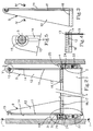
- FIG. 1 and 2 and 6 and 7 preferred embodiments of the Shown inventive drawer shown with an elevated Border are provided, as they are mainly in office furniture drawers and provided for pot drawers in kitchen furniture are.
- FIGs 1 and 2 and 6 and 7 these drawers have a front panel 1 which is based on a drawer with disproportionate dimensions is high, the drawer side walls 2 and one Has rear wall 3, starting from a 90 ° bend achieved by a continuous profile made of sheet metal that is made by pressing.
- the side walls 2 are with quick attachment devices 33 for detachable and adjustable attachment to the front panel 1 of the drawer provided, these side walls 2 and the rear wall 3 a have outward curved bend 4, which in Case of the rear wall 3 for secure attachment of the rear brackets 9 and 10 serves as in the case of the side walls 2
- Guideway for a front wheel 24 is used in the guide 25 is installed, which is anchored to the piece of furniture, the Guide 25, in turn, a guide track for a rear wheel 26 forms, which is attached to the side walls 2.
- Figures 1 and 2 show an embodiment, the particular is suitable for use with office furniture drawers and at which according to the invention, the rear brackets respective single-rod brackets 9 are a one-piece molded plastic have an elongated construction in the vertical direction, with respect to the main directions of the drawer respective vertical longitudinal angle pieces 11 and transverse angle pieces 12 is formed, which are perpendicular to each other and each other penetrate that each of these elbows in shape a respective rib 13 and 14 extended on the opposite Projecting side of the other elbow.
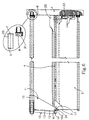
- This Angle pieces 11 and 12 have a reverse in the vertical direction Position such that the longitudinal angle piece 11 or Cross angle piece 12 with its tip down or is directed upwards, with the smaller base edges horizontal are arranged and the smaller base edge of the longitudinal angle piece 11 in a longitudinal half bush 15 with Internal thread ends while the smaller base edge of the cross angle piece 12 ends in a foot 16 provided with a channel, which opens downwards and which extends across the width of these extends smaller base edge with a cross section, the Inner circumference incomplete the outer outline of the arched bend 4 can reach around the rear wall 3 of the shell.
- a foot 16 provided with a channel forms a front one vertical wall 17 and a rear hook-shaped wall 18 with an inward hook that goes under the free edge the curved bend 4 can be brought to bear if by a swiveling movement from the back to the front with a Channel provided foot 16 placed on the curved bend 4 with the front vertical wall 17 of the foot in the vertical direction tion against the inner vertical side of the rear wall 3 of the Drawer comes to the plant.
- the half bush with internal thread 15 encloses an arc of more than 180 ° and has a Internal thread that is complementary to that on a rear threaded tip 19 of a side rod 5 of the border is provided.
- This side rod 5 has on her front end 7 a section 20 for an elastic lateral Latching engagement from top to bottom in a narrowed seat 31 of a rear anchor 8 in the front panel 1.
- the cross angle pieces 12 prevent (Fig. 2) that the hanging files after can fall down if no rear rod 6 is provided is that can be omitted because of the novel ones Single-rod brackets 9 have sufficient structural strength can have for the drawer, because of their novel and special cross-shaped cross section (Fig. 4).
- the Point of view of the longitudinal half-sleeve 15 enables the Impression of the single-rod holder 9 without affecting the Effectiveness of screw fastening.
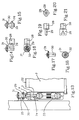
- the appropriate embodiment according to the invention is the one in the figures 6 and 7 is shown.
- the rear brackets Two-rod brackets 10 which are a one-piece, plastic have a shaped and vertically elongated construction, with respect to the main directions of the drawer respective vertical longitudinal angle pieces 11 and transverse angle pieces 12 is formed, which are perpendicular to each other and each other penetrate such that each elbow in the form of a respective rib 13 or 14 extended on the opposite Projecting side of the other elbow.
- elbows 11 and 12 have a reverse in the vertical direction Position such that the longitudinal elbows 11 and the transverse elbows 12 with their tips down or down are directed upwards while their smaller base edges are horizontal lie, the smaller base edge of the longitudinal angle piece 11 in a longitudinal half bush 15 with an internal thread ends while the smaller base edge of the cross angle piece 12 in a channeled foot 16 that ends down is open and along the smaller base edge with a Cross section extends, the inner contour of which is incomplete Outside outline of the arched bend 4 of the rear wall 3 of the drawer circumscribes.
- This cross angle piece 12 is considerable in front of its top area by an upper horizontal Edge 22 interrupted, parallel to its smaller lower one Base edge runs and that in a transverse bushing 23rd ends, which is closed at the end of the outside of the drawer is.
- the transverse one with a channel Foot 16 forms a front vertical wall 17 and a rear hook-shaped wall 18 with an inwardly directed hook 18a, the under the free edge of the curved bend 4 by a Swiveling movement from the back to the front of the provided with the channel Foot 16 brought to the arched bend 4 to the system can be.
- the front vertical wall 17 of the foot can do this in the vertical direction on the inner and vertical edge of the Rear wall 3 of the drawer can be brought into contact.
- the longitudinal, threaded half bush 15 engages around Bend of more than 180 ° and has an internal thread that is complementary to that on a rear threaded tip 19 a respective side rod 5 is provided, which on its front end 7 has a coupling section 20 which thanks to elastic grating from top to bottom in one narrowed seat 21 of the rear anchorages 8 of the front panel 1 can be snapped into place.
- the transverse closed Blind bush 23 of the holder has an inner diameter, the on the outer contour of each end of a rear Rod 6 of the raised border is adapted. How to recognize is, this two-bar bracket 10 corresponds to its concept forth the single-rod holder 9, with the only helpful modification, those for receiving the transverse blind bushes 23 is intended to receive the ends of the rear rod 6th are determined (Fig. 7).
- the attachment is as in the case of the Single-rod bracket 9, with the exception that first the rear Rod 6 is inserted before the second two-rod bracket 10 is installed.
- this Two-rod bracket 10 the longitudinal elbow 11 to the outside of the Drawer be inclined and the vertical of the longitudinal Threaded half-bush 15 may be further out than that End of the channeled foot 16, the more on the The center of the drawer is. In this way, in the The maximum width that can be used in the height Recess for the drawer is available.
Landscapes
- Drawers Of Furniture (AREA)
Applications Claiming Priority (2)
| Application Number | Priority Date | Filing Date | Title |
|---|---|---|---|
| ES9801568 | 1998-07-24 | ||
| ES9801568 | 1998-07-24 |
Publications (1)
| Publication Number | Publication Date |
|---|---|
| EP0974291A2 true EP0974291A2 (fr) | 2000-01-26 |
Family
ID=8304628
Family Applications (1)
| Application Number | Title | Priority Date | Filing Date |
|---|---|---|---|
| EP99113281A Withdrawn EP0974291A2 (fr) | 1998-07-24 | 1999-07-08 | Tiroir pour meubles |
Country Status (1)
| Country | Link |
|---|---|
| EP (1) | EP0974291A2 (fr) |
Cited By (3)
| Publication number | Priority date | Publication date | Assignee | Title |
|---|---|---|---|---|
| DE20101583U1 (de) * | 2001-01-31 | 2002-06-20 | Mepla-Werke Lautenschläger GmbH & Co. KG, 64354 Reinheim | Vorrichtung für die Neigungs-Verstellung von Schubladen-Frontblenden |
| WO2005034683A1 (fr) * | 2003-10-14 | 2005-04-21 | Sige S.P.A. | Barre de retenue pour paniers coulissants disposes a l'interieur de meubles comprenant des portes |
| US20240298794A1 (en) * | 2023-03-06 | 2024-09-12 | King Slide Works Co., Ltd. | Furniture System and Furniture Assembly Thereof |
-
1999
- 1999-07-08 EP EP99113281A patent/EP0974291A2/fr not_active Withdrawn
Cited By (5)
| Publication number | Priority date | Publication date | Assignee | Title |
|---|---|---|---|---|
| DE20101583U1 (de) * | 2001-01-31 | 2002-06-20 | Mepla-Werke Lautenschläger GmbH & Co. KG, 64354 Reinheim | Vorrichtung für die Neigungs-Verstellung von Schubladen-Frontblenden |
| AT413184B (de) * | 2001-01-31 | 2005-12-15 | Lautenschlaeger Mepla Werke | Vorrichtung für die neigungs-verstellung von schubladen-frontblenden |
| WO2005034683A1 (fr) * | 2003-10-14 | 2005-04-21 | Sige S.P.A. | Barre de retenue pour paniers coulissants disposes a l'interieur de meubles comprenant des portes |
| US20240298794A1 (en) * | 2023-03-06 | 2024-09-12 | King Slide Works Co., Ltd. | Furniture System and Furniture Assembly Thereof |
| US12324516B2 (en) * | 2023-03-06 | 2025-06-10 | King Slide Works Co., Ltd. | Furniture system and furniture assembly thereof |
Similar Documents
| Publication | Publication Date | Title |
|---|---|---|
| EP2222202B1 (fr) | Tiroir avec réglage du panneau avant | |
| DE2708167A1 (de) | Schublade aus kunststoff | |
| DE8307469U1 (de) | Schubkasten aus kunststoff fuer moebel | |
| DE4301327A1 (en) | Method of fitting a guide rail to sliding drawer - has spring catch fitted to underside of drawer which engages slot in rail and holds it in place | |
| WO2013087375A1 (fr) | Élément de fixation et grille latérale | |
| EP1166680A1 (fr) | Tiroir | |
| AT515689B1 (de) | Schublade | |
| DE2113398A1 (de) | In Form eines Tisches ausgebildetes Moebelstueck | |
| DE29907856U1 (de) | Führungsvorrichtung zur Aufnahme von Gleit- und Schiebeelementen an Möbeln | |
| EP0974291A2 (fr) | Tiroir pour meubles | |
| DE9102828U1 (de) | Schubkastenführung, insbesondere für Schubkästen aus Metall | |
| DE8531302U1 (de) | Auszugschiene mit einer integrierten Seitenzarge | |
| AT400660B (de) | Ausziehführungsgarnitur für eine schublade | |
| EP2578759A1 (fr) | Mécanisme de verrouillage pour un égout | |
| DE4433577A1 (de) | Möbelauszugsteil | |
| DE19929144B4 (de) | Buchstütze | |
| DE1809813A1 (de) | Trageskelett fuer Verkleidungsplatten | |
| DE4015742C2 (de) | Schließteil-Befestigung an Fenster- oder Türrahmen | |
| DE19828233A1 (de) | Wandkonsole | |
| EP0829213A2 (fr) | Glissière pour tiroirs | |
| DE69928056T2 (de) | Heizkörperhalterung | |
| DE2821101A1 (de) | Moebel-auszugfuehrung | |
| DE102014110280B4 (de) | Adapter für einen Drahtkorb und Schubelement für ein Möbel | |
| DE9210602U1 (de) | Befestigungselement für Verkleidungselemente | |
| EP0678254B1 (fr) | Dispositif de support réglable pour un panneau frontal d'un tiroir ou similaire |
Legal Events
| Date | Code | Title | Description |
|---|---|---|---|
| PUAI | Public reference made under article 153(3) epc to a published international application that has entered the european phase |
Free format text: ORIGINAL CODE: 0009012 |
|
| AK | Designated contracting states |
Kind code of ref document: A2 Designated state(s): AT BE CH CY DE DK ES FI FR GB GR IE IT LI LU MC NL PT SE |
|
| AX | Request for extension of the european patent |
Free format text: AL;LT;LV;MK;RO;SI |
|
| STAA | Information on the status of an ep patent application or granted ep patent |
Free format text: STATUS: THE APPLICATION IS DEEMED TO BE WITHDRAWN |
|
| 18D | Application deemed to be withdrawn |
Effective date: 20030201 |