EP0972603A2 - Procéde et dispositif d'usinage par décharge électrique par fil, et matrice d'extrusion - Google Patents
Procéde et dispositif d'usinage par décharge électrique par fil, et matrice d'extrusion Download PDFInfo
- Publication number
- EP0972603A2 EP0972603A2 EP99113843A EP99113843A EP0972603A2 EP 0972603 A2 EP0972603 A2 EP 0972603A2 EP 99113843 A EP99113843 A EP 99113843A EP 99113843 A EP99113843 A EP 99113843A EP 0972603 A2 EP0972603 A2 EP 0972603A2
- Authority
- EP
- European Patent Office
- Prior art keywords
- electric discharge
- workpiece
- wire
- discharge machining
- machining
- Prior art date
- Legal status (The legal status is an assumption and is not a legal conclusion. Google has not performed a legal analysis and makes no representation as to the accuracy of the status listed.)
- Granted
Links
Images


Classifications
-
- B—PERFORMING OPERATIONS; TRANSPORTING
- B28—WORKING CEMENT, CLAY, OR STONE
- B28B—SHAPING CLAY OR OTHER CERAMIC COMPOSITIONS; SHAPING SLAG; SHAPING MIXTURES CONTAINING CEMENTITIOUS MATERIAL, e.g. PLASTER
- B28B3/00—Producing shaped articles from the material by using presses; Presses specially adapted therefor
- B28B3/20—Producing shaped articles from the material by using presses; Presses specially adapted therefor wherein the material is extruded
- B28B3/26—Extrusion dies
- B28B3/269—For multi-channeled structures, e.g. honeycomb structures
-
- B—PERFORMING OPERATIONS; TRANSPORTING
- B23—MACHINE TOOLS; METAL-WORKING NOT OTHERWISE PROVIDED FOR
- B23H—WORKING OF METAL BY THE ACTION OF A HIGH CONCENTRATION OF ELECTRIC CURRENT ON A WORKPIECE USING AN ELECTRODE WHICH TAKES THE PLACE OF A TOOL; SUCH WORKING COMBINED WITH OTHER FORMS OF WORKING OF METAL
- B23H11/00—Auxiliary apparatus or details, not otherwise provided for
-
- B—PERFORMING OPERATIONS; TRANSPORTING
- B23—MACHINE TOOLS; METAL-WORKING NOT OTHERWISE PROVIDED FOR
- B23H—WORKING OF METAL BY THE ACTION OF A HIGH CONCENTRATION OF ELECTRIC CURRENT ON A WORKPIECE USING AN ELECTRODE WHICH TAKES THE PLACE OF A TOOL; SUCH WORKING COMBINED WITH OTHER FORMS OF WORKING OF METAL
- B23H7/00—Processes or apparatus applicable to both electrical discharge machining and electrochemical machining
- B23H7/36—Supply or regeneration of working media
-
- B—PERFORMING OPERATIONS; TRANSPORTING
- B23—MACHINE TOOLS; METAL-WORKING NOT OTHERWISE PROVIDED FOR
- B23H—WORKING OF METAL BY THE ACTION OF A HIGH CONCENTRATION OF ELECTRIC CURRENT ON A WORKPIECE USING AN ELECTRODE WHICH TAKES THE PLACE OF A TOOL; SUCH WORKING COMBINED WITH OTHER FORMS OF WORKING OF METAL
- B23H9/00—Machining specially adapted for treating particular metal objects or for obtaining special effects or results on metal objects
-
- B—PERFORMING OPERATIONS; TRANSPORTING
- B23—MACHINE TOOLS; METAL-WORKING NOT OTHERWISE PROVIDED FOR
- B23H—WORKING OF METAL BY THE ACTION OF A HIGH CONCENTRATION OF ELECTRIC CURRENT ON A WORKPIECE USING AN ELECTRODE WHICH TAKES THE PLACE OF A TOOL; SUCH WORKING COMBINED WITH OTHER FORMS OF WORKING OF METAL
- B23H2200/00—Specific machining processes or workpieces
- B23H2200/30—Specific machining processes or workpieces for making honeycomb structures
Definitions
- the present invention relates to a wire electric discharge machining apparatus and a wire electric discharge machining method for effecting electric discharge between a wire electrode and a workpiece to machine the workpiece to have an arbitrary shape.
- the present invention also relates to a mold for extrusion produced by the wire electric discharge machining apparatus and the wire electric discharge machining method.
- the wire electric discharge machining which is one of the cutting machining procedures based on the use of a thin wire electrode, the discharge phenomenon is allowed to occur between the wire electrode and the workpiece. Therefore, the wire electric discharge machining is advantageous in that the machining can be performed irrelevant to the characteristic values of a material such as the strength, the hardness, and the toughness of the workpiece. Further, the wire electric discharge machining has the following advantages.
- the wire electric discharge machining is also advantageous to machine thin workpieces, those having a fragile quality, and those having fine shapes such as extremely small holes and slits.
- Japanese Laid-Open Patent Publication No. 56-152531 describes the use of a wire provided with grooves, projections, and irregularities on its surface to discharge the sludge or the like.
- Japanese Laid-Open Utility Model Publication No. 62-110816 describes the use of a wire having a triangular, rectangular, or elliptic cross-sectional configuration so that the wire is rotated and fed to discharge the sludge or the like.
- Japanese Laid-Open Patent Publication No. 1-222821 describes the use of a wire composed of a wire having a straight angle cross section formed to give a helical configuration to discharge the sludge or the like.
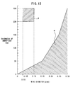
- the wire electric discharge machining involves a standard machinable range which is the range ⁇ indicated by hatched lines. If the condition is deviated from this range, the following problems occur. That is, it is impossible to perform the machining to give a desired shape, the breaking of wire occurs, and the machining groove width is abnormally enlarged. For example, it is assumed that a machining groove having a width of 0.05 mm to 0.12 mm is intended to be formed on a workpiece having a thickness of 200 mm to 250 mm. This condition lies in a range ß indicated by dashed lines in FIG. 13, which is a condition far apart from the standard machining condition.
- the machining which is performed under a condition as described above, is exemplified by the formation of a mold for producing, by extrusion, honeycomb ceramics which is used, for example, for a catalyst for automobiles, especially, for example, the formation of a slit for defining the opening width of the cell of the honeycomb ceramics.
- the electric discharge machining can be performed with a prescribed machining groove at the early stage of the electric discharge machining.
- the sludge or the like tends to accumulate between the wire electrode and the machining groove. It is feared that any unstable electric discharge such as secondary electric discharge may occur on account of the sludge to cause the enlargement of the machining groove width and the breaking of the wire electrode.
- the purpose of the conventional method described above is that the electric discharge machining is well performed persistently under the standard machining condition.
- the conventional method does not assume any electric discharge machining under conditions deviated from the standard machining condition as described above, because of the following reason. That is, the conventional method uses the wire having the specified shape from the early stage of the electric discharge machining (in which the standard machining condition is almost satisfied). Therefore, it is inevitable that the machining groove width is widened, which is not suitable to form the slit for defining the opening width of the cell of the honeycomb ceramics as described above.
- the present invention has been made taking the foregoing problems into consideration, an object of which is to provide a wire electric discharge machining apparatus and a wire electric discharge machining method which make it possible to easily form, by means of the wire electric discharge machining, a machining groove having a narrow width and a large depth under a condition deviated from the general standard machining condition for the wire electric discharge machining, for example, for a workpiece having a large thickness, and which make it possible to produce, for example, a slit for defining the opening width of a cell of honeycomb ceramics exactly as designed.
- Another object of the present invention is to provide a mold for extrusion, which makes it possible to easily produce, for example, honeycomb ceramics having a thin partition wall by means of extrusion.
- a wire electric discharge machining apparatus comprising a wire-driving system for feeding a wire electrode while opposing the wire electrode to a workpiece, and a power supply unit for supplying electric power to the wire electrode, wherein electric discharge is effected between the wire electrode and the workpiece to machine the workpiece to have an arbitrary shape, the wire electric discharge machining apparatus further comprising a suction mechanism connected to a plurality of holes communicating with machining grooves to be formed on the workpiece by the wire electrode, for sucking undesirable matters including sludge from the machining grooves via the plurality of holes.
- the wire electric discharge machining apparatus further comprises a machining tank for storing a working fluid to immerse the workpiece therein, or a working fluid supply mechanism for supplying a working fluid to an electric discharge machining site on the workpiece or vicinity thereof, wherein the suction mechanism sucks the undesirable matters together with the working fluid.
- a machining tank for storing a working fluid to immerse the workpiece therein
- a working fluid supply mechanism for supplying a working fluid to an electric discharge machining site on the workpiece or vicinity thereof, wherein the suction mechanism sucks the undesirable matters together with the working fluid.
- the suction mechanism includes a plurality of cylindrical members for being inserted into the plurality of holes, and a holding member for holding the plurality of cylindrical members.
- a wire electric discharge machining method comprising the steps of feeding a wire electrode by using a wire-driving system while opposing the wire electrode to a workpiece, and supplying electric power to the wire electrode by using a power supply unit so that electric discharge is effected between the wire electrode and the workpiece to machine the workpiece to have an arbitrary shape, wherein the workpiece is machined while sucking, by using a suction mechanism, undesirable matters including sludge through a plurality of holes communicating with machining grooves to be formed on the workpiece by the wire electrode.
- the undesirable matters are sucked by using the suction mechanism together with a working fluid in which an electric discharge machining site on the workpiece is immersed. By doing so, the undesirable matters can be preferably removed while applying the electric discharge.
- a mold for extrusion comprising a large number of slits formed in a lattice-shaped configuration through its front surface, and a large number of body-introducing holes provided on a side of its back surface for supplying a body to the large number of slits, wherein the large number of slits are formed by wire electric discharge machining while sucking, through the body-introducing holes, undesirable matters including sludge generated during the wire electric discharge machining.
- the machining groove is formed by the wire electric discharge machining while removing the undesirable matters generated during the wire electric discharge machining. Therefore, it is possible to easily form, by means of the wire electric discharge machining, a machining groove having a narrow width and a large depth under a condition deviated from the general standard machining condition for the wire electric discharge machining, for example, even for a mold having a large thickness.
- the slit of the mold is formed by using the wire electric discharge machining. Therefore, for example, when honeycomb ceramics having a thin partition wall is produced by using the extrusion mold according to the present invention, it is possible to easily produce the honeycomb ceramics in which, for example, the opening width of the cell is extremely small, and the conformation of the cell is not deteriorated.
- wire electric discharge machining apparatus for an illustrative embodiment in which the wire electric discharge machining apparatus according to the present invention is applied, for example, to a mold for producing, by extrusion, honeycomb ceramics to be used for an automobile catalyst, especially to a case in which a slit is formed to define the opening width of the cell of the honeycomb ceramic (hereinafter simply referred to as "wire electric discharge machining apparatus according to the embodiment").
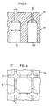
- the extrusion mold 12 comprises a slit section 18 including a large number of slits (machining grooves) 16 formed in a lattice-shaped configuration (see FIG. 4) through its front surface, and a body-introducing section 22 including a large number of body-introducing holes 20 formed on the side of its back surface for supplying the body to the large number of slits 16 of the slit section 18.
- the respective body-introducing holes 20 of the body-introducing section 22 are formed by means of the drill machining.
- the respective slits 16 of the slit section 18 are formed by means of the wire electric discharge machining as described later on so that they have, for example, a depth of 5 mm.
- a plurality of holes 24 each having, for example, a diameter of 100 ⁇ m to 200 ⁇ m are previously formed, for example, by means of the electric discharge machining on the slit section 18 of the extrusion mold 12 before the slits 16 are formed.
- the holes 24 communicate with the body-introducing holes 20 from positions corresponding to points of intersection of the respective slits 16.
- the diameter of the hole 24 is formed to be the same as the width t of the slit 16 or to be slightly smaller than the width t of the slit 16. It is unnecessary to form the holes 24 at all of the positions corresponding to the points of intersection of the slits 16.
- the holes 24 may be formed, for example, on every second one depending on the width of the slit 16.
- the honeycomb ceramics 14 shown in FIG. 5 is formed by using the extrusion mold 12.
- the thickness of the partition wall 32 of each of the cells 30 of the honeycomb ceramics 14 is substantially coincident with the width t of the slit 16, and it can be formed to be extremely thin.
- a catalyst carrier which is obtained by sintering the honeycomb ceramics 14, can be also formed to have an extremely thin thickness of the partition wall 32 between the cells 30. Accordingly, for example, such a catalyst carrier is light in weight to be used for cleaning the exhaust gas discharged from the automobile. Further, the temperature can be raised for a short period of time when the engine is started. Therefore, it is possible to clean the exhaust gas without any trouble.
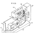
- the wire electric discharge machining apparatus 10 comprises a column 102 on which a main apparatus body 100 of the wire electric discharge machining apparatus 10 is attached, and an XY table 104 for moving the workpiece W together with a machining tank 116 as described later on in the horizontal direction (XY direction).
- the column 102 and the XY table 104 are placed on the upper surface of a base pedestal 106.
- the main apparatus body 100 includes an upper arm 108 which extends in the horizontal direction from an upper portion of the column 102 to a position over the XY table 104 and which is movable in the axial direction of the column 102 by the aid of an unillustrated first movement drive mechanism, and a lower arm 110 which extends downwardly from a lower surface portion of the upper arm 108 near to the column 102.
- An upper support plate 112 which extends in parallel to the upper arm 108 and which is movable in the axial direction of the lower arm 110 by the aid of an unillustrated second movement drive mechanism, is provided on the upper front surface (portion close to the upper arm 108) of the lower arm 110.
- a lower support plate 114 which extends in parallel to the upper arm 108, is integrally provided at the lower front surface (portion close to the XY table 104) of the lower arm 110.
- a machining tank 116 is fixed on the upper surface of the XY table 104.
- a workpiece-holding mechanism 118 for holding and fixing the workpiece W is attached in the machining tank 116.
- a working fluid for example, ion-exchanged water having an electrical resistivity of not less than 10 3 ⁇ ⁇ cm
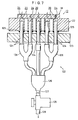
- the workpiece-holding mechanism 118 is provided with a holding member 123 for constructing a suction mechanism 122. As shown in FIG. 10 a plurality of cylindrical members 124 are formed to stand on the holding member 123. As shown in FIG. 7, each of the cylindrical members 124 is inserted into the body-introducing hole 20 of the extrusion mold 12 as the workpiece W. A ring-shaped packing member 125, which is made of a material such as rubber, is installed to the cylindrical member 124.
- the plurality of cylindrical members 124 are connected to a single tube 127 via a plurality of distributive joints 126.
- the tube 127 is connected to a pump 128.
- a discharge port 129 is provided for the pump 128.
- the wire electric discharge machining apparatus 10 is provided with a wire-driving system 132 for feeding a wire electrode 130 while opposing it to the workpiece W, the wire electrode 130 being made of, for example, copper, Cu-Zn, or tungsten, and an upper power supply unit 170 and a lower power supply unit 172 for supplying the electric power to the wire electrode 130.
- the wire-driving system 132 comprises a wire supply section 136 provided on a side surface of the upper arm 108, and a wire-winding section 138 provided on a side surface of the lower arm 110.
- the upper power supply unit 170 is provided on an end side surface portion of the upper support plate 112.
- the lower power supply unit 172 is provided on an end side surface portion of the lower support plate 114.
- the wire supply section 136 comprises a wire supply bobbin 150 with a large number of turns of the linear wire electrode 130 wound therearound, first to third pulleys 152a to 152c for introducing, to the upper power supply unit 170, the wire electrode 130 led from the wire supply bobbin 150, a brake roller 154 provided between the second and third pulleys 152b, 152c for controlling the feed speed of the wire electrode 130, and a wire holder 156 provided between the brake roller 154 and the third pulley 152c for applying the load to the wire electrode 130 to adjust the tension of the wire electrode 130.
- the wire-winding section 138 comprises a wire-winding bobbin 160 for winding the used wire electrode 130 (wire electrode 130 led through the lower power supply unit 172) completed for the electric discharge machining for the workpiece W, a fourth pulley 152d provided in the vicinity of an end lower surface portion of the lower support plate 114, a wire-winding roller 162 for leading the used wire electrode 130 toward the lower arm 110 by being guided by the fourth pulley 152d, a pinch roller 164 for transporting, to the wire-winding bobbin 160, the used wire electrode 130 wound by the wire-winding roller 162, and a wire-aligning/winding unit 166 for aligning and winding the used wire electrode 130 around the wire-winding bobbin 160.
- the upper support plate 112 is provided with an upper nozzle 140 for jetting the working fluid 120 downwardly along the feed direction of the wire electrode 130 in order to cool the machining portion processed by the wire electric discharge machining.
- the lower support plate 114 is also provided with a lower nozzle 142 for jetting the working fluid 120 upwardly along the feed direction of the wire electrode 130 in order to cool the machining portion processed by the wire electric discharge machining.
- the wire electric discharge machining apparatus 10 is used as follows. At first, in order to attach the workpiece W to the workpiece-holding mechanism 118 installed in the machining tank 116, the upper arm 108 is moved upwardly by the aid of the unillustrated first movement drive mechanism. After that, the workpiece W is installed to the holding member 123 of the suction mechanism 122 (see FIG. 7) to be held by the workpiece-holding mechanism 118. Accordingly, the holes 24 communicate with the pump 128 via the cylindrical members 124. After that, the working fluid 120 is poured into the machining tank 116 until the workpiece W is immersed therein.
- the upper arm 108 is moved downwardly by the aid of the unillustrated first movement drive mechanism, and then the upper support plate 112 is moved upwardly or downwardly corresponding to the thickness T of the workpiece W by the aid of the unillustrated second movement drive mechanism.
- the machining tank 116 is moved by driving the XY table 104 so that the workpiece W held by the workpiece-holding mechanism 118 approaches the wire electrode 130 while feeding the wire electrode 130 from the wire supply bobbin 150.
- the electric discharge is started from the stage at which the wire electrode 130 subjected to the feed process is opposed to the workpiece W and it closely approaches the workpiece W.
- the machining groove 180 is formed by the electric discharge on the workpiece W until the depth is equal to the depth of the hole 24.
- the pump 128 is operated, and the working fluid 120, in which the workpiece W is immersed, is sucked by the pump 128 from the holes 24 communicating with the machining groove 180, via the body-introducing holes 20 and the cylindrical members 124 (see FIGS. 7 and 8). Accordingly, undesirable matters including sludge, which are generated between the machining groove 180 and the wire electrode 130 during the electric discharge machining, are sucked together with the working fluid 120 to avoid any factor such as secondary electric discharge which would otherwise result in enlargement of the machining groove 180. Further, it is possible to decrease the fear of breaking of the wire electrode 130 as well.
- the machining groove 180 having a narrow width t and a large depth f under a condition deviated from the general standard machining condition for the wire electric discharge machining, for example, even for a workpiece W having a large thickness T.
- undesirable matters such as sludge can be efficiently sucked by decreasing the spacing distance between the holes 24. Therefore, the wire electric discharge machining can be performed even when the thickness T of the workpiece W is large, or even when the width t of the machining groove 180 is narrow.
- the wire electric discharge machining apparatus 10 makes it possible to form the machining groove up to a range which is far apart from the range specified by an upper limit indicated by the solid line A, i.e., up to a range specified by an upper limit indicated by the solid line B.
- a machining groove 180 having a machining slit width t of 0.02 to 0.05 mm for a machining thickness T of 220 mm to 300 mm.
- the maximum value of the machining thickness T is 300 mm, because the stroke of the wire electric discharge machining apparatus 10 is 300 mm.
- the machining can be effected up to a range specified by an upper limit indicated by a broken line C depicted along an extension line of the solid line B.
- a catalyst carrier which is obtained by sintering the honeycomb ceramics 14, can be also formed to have an extremely thin thickness of the partition wall 32 between the cells 30. Accordingly, for example, such a catalyst carrier is light in weight to be used for cleaning the exhaust gas discharged from the automobile. Further, the temperature can be raised for a short period of time when the engine is started. It is possible to clean the exhaust gas without any trouble.
- the wire electric discharge machining apparatus 10 can be constructed merely by applying the simple change in design to the wire electric discharge machining apparatus which has been hitherto used.
- the wire electric discharge machining is performed by immersing the workpiece W in the working fluid 120 stored in the machining tank 116.
- the wire electric discharge machining may be performed while supplying the working fluid 120 to the machining site of the workpiece W by using an unillustrated working fluid supply mechanism.
- the wire electric discharge machining apparatus, the wire electric discharge machining method, and the mold for extrusion according to the present invention are not limited to the embodiments described above, which may be embodied in other various forms without deviating from the gist or essential characteristics of the present invention.
- a wire electric discharge machining apparatus comprising a wire-driving system (132) for feeding a wire electrode (130) while opposing it to a workpiece (W), and a power supply unit (170, 172) for supplying electric power to the wire electrode (130), wherein electric discharge is effected between the wire electrode (130) and the workpiece (W) to machine the workpiece (W) to have an arbitrary shape.
- the wire electrode (130) is allowed to make approach to the workpiece (W) to effect the electric discharge between the wire electrode (130) and the workpiece (W) so that the workpiece is machined to have an arbitrary shape, while a suction mechanism (122) is used to suck undesirable matters including sludge together with a working fluid (120) via cylindrical members (124) from holes (20) formed in the workpiece (W). Accordingly, it is possible to easily form, by means of the wire electric discharge machining, a machining groove (180) having a narrow width and a large depth under a condition deviated from the general standard machining condition for the wire electric discharge machining, for example, even for a workpiece (W) having a large thickness.
Applications Claiming Priority (2)
| Application Number | Priority Date | Filing Date | Title |
|---|---|---|---|
| JP20202598A JP3478730B2 (ja) | 1998-07-16 | 1998-07-16 | ワイヤ放電加工装置、ワイヤ放電加工方法及び押出成形用金型 |
| JP20202598 | 1998-07-16 |
Publications (3)
| Publication Number | Publication Date |
|---|---|
| EP0972603A2 true EP0972603A2 (fr) | 2000-01-19 |
| EP0972603A3 EP0972603A3 (fr) | 2000-12-27 |
| EP0972603B1 EP0972603B1 (fr) | 2003-11-12 |
Family
ID=16450685
Family Applications (1)
| Application Number | Title | Priority Date | Filing Date |
|---|---|---|---|
| EP99113843A Expired - Lifetime EP0972603B1 (fr) | 1998-07-16 | 1999-07-15 | Procéde et dispositif d'usinage par décharge électrique par fil, et matrice d'extrusion |
Country Status (4)
| Country | Link |
|---|---|
| US (1) | US6320150B1 (fr) |
| EP (1) | EP0972603B1 (fr) |
| JP (1) | JP3478730B2 (fr) |
| DE (1) | DE69912690T2 (fr) |
Cited By (4)
| Publication number | Priority date | Publication date | Assignee | Title |
|---|---|---|---|---|
| EP1529584A1 (fr) * | 2003-11-06 | 2005-05-11 | Schunk GmbH & Co. KG Spann- und Greiftechnik | Manchon pour un mandrin et son procédé de fabrication |
| US7335848B2 (en) | 2004-03-09 | 2008-02-26 | Ngk Insulators, Ltd. | Process for production of die usable for formation of honeycomb structure |
| CN103949734A (zh) * | 2014-05-16 | 2014-07-30 | 郑兴义 | 一种可快速冷却的电火花线切割机床 |
| CN104759719A (zh) * | 2015-04-21 | 2015-07-08 | 清华大学 | 微小圆弧形薄片上微凹槽线放电磨削加工工艺及导向片 |
Families Citing this family (6)
| Publication number | Priority date | Publication date | Assignee | Title |
|---|---|---|---|---|
| JP2004322234A (ja) * | 2003-04-22 | 2004-11-18 | Fukuoka Prefecture | 導電性砥石の加工装置及び加工方法 |
| JP2012125883A (ja) * | 2010-12-15 | 2012-07-05 | Ngk Insulators Ltd | ハニカム構造体成形口金用電極の製造方法 |
| CN102528189B (zh) * | 2010-12-24 | 2013-09-25 | 沈阳黎明航空发动机(集团)有限责任公司 | 一种高精度薄壁环形件加工工艺 |
| CN103769705B (zh) * | 2014-01-17 | 2016-06-15 | 清华大学 | 一种用于深小孔电火花加工的多功能主轴机构 |
| CN107206518B (zh) | 2014-11-26 | 2019-05-14 | 康宁股份有限公司 | 用于制造挤出模具的设备和方法 |
| CN109465512A (zh) * | 2018-12-28 | 2019-03-15 | 太仓新思成模具钢有限公司 | 一种用于模具钢切割的介质喷头 |
Citations (3)
| Publication number | Priority date | Publication date | Assignee | Title |
|---|---|---|---|---|
| JPS56152531A (en) | 1980-04-22 | 1981-11-26 | Mitsubishi Electric Corp | Wire-cut electric discharge machining method and its device |
| JPS62110816A (ja) | 1985-11-08 | 1987-05-21 | Kawasaki Steel Corp | コイル状鋼板の巻戻し方法 |
| JPH01222821A (ja) | 1988-02-26 | 1989-09-06 | Mitsubishi Electric Corp | ワイヤカット放電加工装置 |
Family Cites Families (3)
| Publication number | Priority date | Publication date | Assignee | Title |
|---|---|---|---|---|
| US4527035A (en) * | 1981-07-30 | 1985-07-02 | Corning Glass Works | Wire electrical discharge machine flushing process and apparatus |
| JP3382982B2 (ja) * | 1992-10-26 | 2003-03-04 | 株式会社ソディック | 放電加工機の加工液噴流・吸引装置 |
| US5630951A (en) | 1995-05-15 | 1997-05-20 | Corning Incorporated | Methods and apparatus for making honeycomb extrusion dies |
-
1998
- 1998-07-16 JP JP20202598A patent/JP3478730B2/ja not_active Expired - Fee Related
-
1999
- 1999-07-12 US US09/351,582 patent/US6320150B1/en not_active Expired - Fee Related
- 1999-07-15 EP EP99113843A patent/EP0972603B1/fr not_active Expired - Lifetime
- 1999-07-15 DE DE69912690T patent/DE69912690T2/de not_active Expired - Fee Related
Patent Citations (3)
| Publication number | Priority date | Publication date | Assignee | Title |
|---|---|---|---|---|
| JPS56152531A (en) | 1980-04-22 | 1981-11-26 | Mitsubishi Electric Corp | Wire-cut electric discharge machining method and its device |
| JPS62110816A (ja) | 1985-11-08 | 1987-05-21 | Kawasaki Steel Corp | コイル状鋼板の巻戻し方法 |
| JPH01222821A (ja) | 1988-02-26 | 1989-09-06 | Mitsubishi Electric Corp | ワイヤカット放電加工装置 |
Cited By (6)
| Publication number | Priority date | Publication date | Assignee | Title |
|---|---|---|---|---|
| EP1529584A1 (fr) * | 2003-11-06 | 2005-05-11 | Schunk GmbH & Co. KG Spann- und Greiftechnik | Manchon pour un mandrin et son procédé de fabrication |
| WO2005044489A1 (fr) * | 2003-11-06 | 2005-05-19 | Schunk Gmbh & Co. Kg Spann- Und Greiftechnik | Manchon intermediaire pour mandrin de serrage et procede de production correspondant |
| CN100387386C (zh) * | 2003-11-06 | 2008-05-14 | 雄克有限公司 | 卡盘的中间轴衬及其制造方法 |
| US7335848B2 (en) | 2004-03-09 | 2008-02-26 | Ngk Insulators, Ltd. | Process for production of die usable for formation of honeycomb structure |
| CN103949734A (zh) * | 2014-05-16 | 2014-07-30 | 郑兴义 | 一种可快速冷却的电火花线切割机床 |
| CN104759719A (zh) * | 2015-04-21 | 2015-07-08 | 清华大学 | 微小圆弧形薄片上微凹槽线放电磨削加工工艺及导向片 |
Also Published As
| Publication number | Publication date |
|---|---|
| JP3478730B2 (ja) | 2003-12-15 |
| JP2000033521A (ja) | 2000-02-02 |
| US6320150B1 (en) | 2001-11-20 |
| DE69912690D1 (de) | 2003-12-18 |
| EP0972603A3 (fr) | 2000-12-27 |
| EP0972603B1 (fr) | 2003-11-12 |
| DE69912690T2 (de) | 2004-09-23 |
Similar Documents
| Publication | Publication Date | Title |
|---|---|---|
| US4441004A (en) | Multiple pipe element electrode assembly EDM method and apparatus | |
| JP5789070B2 (ja) | 分散形アーク電食 | |
| EP0972603B1 (fr) | Procéde et dispositif d'usinage par décharge électrique par fil, et matrice d'extrusion | |
| EP3225342A1 (fr) | Procédé et appareil d'usinage de pièces | |
| JP2001287119A (ja) | 細穴放電加工方法および細穴放電加工装置 | |
| EP0161046A1 (fr) | Enfilage automatique de fil avec électrode tubulaire dans une machine d'électro-érosion à fil mobile | |
| KR100449882B1 (ko) | 허니컴압출다이및그제조방법 | |
| JP3815329B2 (ja) | 細穴加工用放電加工装置 | |
| US4527035A (en) | Wire electrical discharge machine flushing process and apparatus | |
| US4543460A (en) | Generic electrode EDM method and apparatus, and assembly for maintaining chip concentration in the gap at an enhanced level | |
| US4430167A (en) | Method of and apparatus for electrodepositing a metal on a substrate | |
| JP5541141B2 (ja) | 放電加工装置 | |
| JPS6355416B2 (fr) | ||
| US4458130A (en) | Immersion-type traveling-wire electroerosion machining method | |
| US6642469B2 (en) | Electrode clamping system for sink-type electrical discharge machines | |
| JPS61131824A (ja) | 数値制御装置 | |
| JP4247932B2 (ja) | ワイヤ放電加工装置 | |
| JP2002273626A (ja) | ハニカム構造体成形用金型の製造方法 | |
| CN217596106U (zh) | 一种慢走丝电火花线切割/电火花穿孔加工一体化机床 | |
| JP2002254247A (ja) | 型彫り微細放電加工による高効率孔加工方法 | |
| JPS63114825A (ja) | 放電加工装置 | |
| JP2571929B2 (ja) | 複合放電加工装置 | |
| JPH0976123A (ja) | 放電加工工具電極及びこれを使用した放電加工機 | |
| JPS61111857A (ja) | 小径穴加工装置 | |
| KR950009288B1 (ko) | 미세구멍을 갖는 세라믹 구조물의 가공장치 및 가공방법 |
Legal Events
| Date | Code | Title | Description |
|---|---|---|---|
| PUAI | Public reference made under article 153(3) epc to a published international application that has entered the european phase |
Free format text: ORIGINAL CODE: 0009012 |
|
| 17P | Request for examination filed |
Effective date: 19990715 |
|
| AK | Designated contracting states |
Kind code of ref document: A2 Designated state(s): BE CH DE FR GB IT LI |
|
| AX | Request for extension of the european patent |
Free format text: AL;LT;LV;MK;RO;SI |
|
| PUAL | Search report despatched |
Free format text: ORIGINAL CODE: 0009013 |
|
| AK | Designated contracting states |
Kind code of ref document: A3 Designated state(s): AT BE CH CY DE DK ES FI FR GB GR IE IT LI LU MC NL PT SE |
|
| AX | Request for extension of the european patent |
Free format text: AL;LT;LV;MK;RO;SI |
|
| RIC1 | Information provided on ipc code assigned before grant |
Free format text: 7B 23H 9/00 A, 7B 28B 3/20 B, 7B 23H 7/36 B |
|
| AKX | Designation fees paid |
Free format text: BE CH DE FR GB IT LI |
|
| 17Q | First examination report despatched |
Effective date: 20020418 |
|
| GRAH | Despatch of communication of intention to grant a patent |
Free format text: ORIGINAL CODE: EPIDOS IGRA |
|
| GRAS | Grant fee paid |
Free format text: ORIGINAL CODE: EPIDOSNIGR3 |
|
| GRAA | (expected) grant |
Free format text: ORIGINAL CODE: 0009210 |
|
| AK | Designated contracting states |
Kind code of ref document: B1 Designated state(s): BE CH DE FR GB IT LI |
|
| REG | Reference to a national code |
Ref country code: GB Ref legal event code: FG4D |
|
| REG | Reference to a national code |
Ref country code: CH Ref legal event code: EP |
|
| REF | Corresponds to: |
Ref document number: 69912690 Country of ref document: DE Date of ref document: 20031218 Kind code of ref document: P |
|
| REG | Reference to a national code |
Ref country code: CH Ref legal event code: NV Representative=s name: ISLER & PEDRAZZINI AG |
|
| ET | Fr: translation filed | ||
| PLBE | No opposition filed within time limit |
Free format text: ORIGINAL CODE: 0009261 |
|
| STAA | Information on the status of an ep patent application or granted ep patent |
Free format text: STATUS: NO OPPOSITION FILED WITHIN TIME LIMIT |
|
| 26N | No opposition filed |
Effective date: 20040813 |
|
| PGFP | Annual fee paid to national office [announced via postgrant information from national office to epo] |
Ref country code: GB Payment date: 20050627 Year of fee payment: 7 |
|
| PGFP | Annual fee paid to national office [announced via postgrant information from national office to epo] |
Ref country code: FR Payment date: 20050719 Year of fee payment: 7 |
|
| PGFP | Annual fee paid to national office [announced via postgrant information from national office to epo] |
Ref country code: CH Payment date: 20050722 Year of fee payment: 7 |
|
| PGFP | Annual fee paid to national office [announced via postgrant information from national office to epo] |
Ref country code: BE Payment date: 20050725 Year of fee payment: 7 |
|
| PGFP | Annual fee paid to national office [announced via postgrant information from national office to epo] |
Ref country code: DE Payment date: 20050830 Year of fee payment: 7 |
|
| PG25 | Lapsed in a contracting state [announced via postgrant information from national office to epo] |
Ref country code: GB Free format text: LAPSE BECAUSE OF NON-PAYMENT OF DUE FEES Effective date: 20060715 |
|
| PG25 | Lapsed in a contracting state [announced via postgrant information from national office to epo] |
Ref country code: LI Free format text: LAPSE BECAUSE OF NON-PAYMENT OF DUE FEES Effective date: 20060731 Ref country code: CH Free format text: LAPSE BECAUSE OF NON-PAYMENT OF DUE FEES Effective date: 20060731 Ref country code: BE Free format text: LAPSE BECAUSE OF NON-PAYMENT OF DUE FEES Effective date: 20060731 |
|
| PGFP | Annual fee paid to national office [announced via postgrant information from national office to epo] |
Ref country code: IT Payment date: 20060731 Year of fee payment: 8 |
|
| PG25 | Lapsed in a contracting state [announced via postgrant information from national office to epo] |
Ref country code: DE Free format text: LAPSE BECAUSE OF NON-PAYMENT OF DUE FEES Effective date: 20070201 |
|
| REG | Reference to a national code |
Ref country code: CH Ref legal event code: PL |
|
| GBPC | Gb: european patent ceased through non-payment of renewal fee |
Effective date: 20060715 |
|
| REG | Reference to a national code |
Ref country code: FR Ref legal event code: ST Effective date: 20070330 |
|
| BERE | Be: lapsed |
Owner name: *NGK INSULATORS LTD Effective date: 20060731 |
|
| PG25 | Lapsed in a contracting state [announced via postgrant information from national office to epo] |
Ref country code: FR Free format text: LAPSE BECAUSE OF NON-PAYMENT OF DUE FEES Effective date: 20060731 |
|
| PG25 | Lapsed in a contracting state [announced via postgrant information from national office to epo] |
Ref country code: IT Free format text: LAPSE BECAUSE OF NON-PAYMENT OF DUE FEES Effective date: 20070715 |