EP0971217B1 - Diagnosesystem für unerwarteten Rausch in einer Vielfach-komponent-Anordnung - Google Patents
Diagnosesystem für unerwarteten Rausch in einer Vielfach-komponent-Anordnung Download PDFInfo
- Publication number
- EP0971217B1 EP0971217B1 EP99305337A EP99305337A EP0971217B1 EP 0971217 B1 EP0971217 B1 EP 0971217B1 EP 99305337 A EP99305337 A EP 99305337A EP 99305337 A EP99305337 A EP 99305337A EP 0971217 B1 EP0971217 B1 EP 0971217B1
- Authority
- EP
- European Patent Office
- Prior art keywords
- target component
- noise
- vibration generation
- generation means
- kit according
- Prior art date
- Legal status (The legal status is an assumption and is not a legal conclusion. Google has not performed a legal analysis and makes no representation as to the accuracy of the status listed.)
- Expired - Lifetime
Links
- 238000005259 measurement Methods 0.000 claims description 9
- 230000001939 inductive effect Effects 0.000 claims description 8
- 239000002390 adhesive tape Substances 0.000 claims 1
- 238000000034 method Methods 0.000 description 17
- 238000012546 transfer Methods 0.000 description 12
- 230000004044 response Effects 0.000 description 10
- 230000005284 excitation Effects 0.000 description 9
- 238000001914 filtration Methods 0.000 description 5
- 238000013459 approach Methods 0.000 description 3
- 230000008901 benefit Effects 0.000 description 3
- 238000010586 diagram Methods 0.000 description 3
- 238000012360 testing method Methods 0.000 description 3
- 238000005070 sampling Methods 0.000 description 2
- 238000001228 spectrum Methods 0.000 description 2
- 230000009466 transformation Effects 0.000 description 2
- 230000003044 adaptive effect Effects 0.000 description 1
- 230000005540 biological transmission Effects 0.000 description 1
- 238000013461 design Methods 0.000 description 1
- 238000003745 diagnosis Methods 0.000 description 1
- 230000009977 dual effect Effects 0.000 description 1
- 230000007274 generation of a signal involved in cell-cell signaling Effects 0.000 description 1
- 230000007246 mechanism Effects 0.000 description 1
- 230000008439 repair process Effects 0.000 description 1
- 238000005316 response function Methods 0.000 description 1
- 230000003595 spectral effect Effects 0.000 description 1
- 230000002889 sympathetic effect Effects 0.000 description 1
Images

Classifications
-
- G—PHYSICS
- G05—CONTROLLING; REGULATING
- G05B—CONTROL OR REGULATING SYSTEMS IN GENERAL; FUNCTIONAL ELEMENTS OF SUCH SYSTEMS; MONITORING OR TESTING ARRANGEMENTS FOR SUCH SYSTEMS OR ELEMENTS
- G05B23/00—Testing or monitoring of control systems or parts thereof
- G05B23/02—Electric testing or monitoring
- G05B23/0205—Electric testing or monitoring by means of a monitoring system capable of detecting and responding to faults
- G05B23/0218—Electric testing or monitoring by means of a monitoring system capable of detecting and responding to faults characterised by the fault detection method dealing with either existing or incipient faults
- G05B23/0256—Electric testing or monitoring by means of a monitoring system capable of detecting and responding to faults characterised by the fault detection method dealing with either existing or incipient faults injecting test signals and analyzing monitored process response, e.g. injecting the test signal while interrupting the normal operation of the monitored system; superimposing the test signal onto a control signal during normal operation of the monitored system
-
- G—PHYSICS
- G01—MEASURING; TESTING
- G01M—TESTING STATIC OR DYNAMIC BALANCE OF MACHINES OR STRUCTURES; TESTING OF STRUCTURES OR APPARATUS, NOT OTHERWISE PROVIDED FOR
- G01M17/00—Testing of vehicles
- G01M17/007—Wheeled or endless-tracked vehicles
-
- B—PERFORMING OPERATIONS; TRANSPORTING
- B60—VEHICLES IN GENERAL
- B60G—VEHICLE SUSPENSION ARRANGEMENTS
- B60G2400/00—Indexing codes relating to detected, measured or calculated conditions or factors
- B60G2400/80—Exterior conditions
- B60G2400/82—Ground surface
- B60G2400/821—Uneven, rough road sensing affecting vehicle body vibration
-
- B—PERFORMING OPERATIONS; TRANSPORTING
- B60—VEHICLES IN GENERAL
- B60G—VEHICLE SUSPENSION ARRANGEMENTS
- B60G2400/00—Indexing codes relating to detected, measured or calculated conditions or factors
- B60G2400/90—Other conditions or factors
- B60G2400/91—Frequency
-
- B—PERFORMING OPERATIONS; TRANSPORTING
- B60—VEHICLES IN GENERAL
- B60G—VEHICLE SUSPENSION ARRANGEMENTS
- B60G2600/00—Indexing codes relating to particular elements, systems or processes used on suspension systems or suspension control systems
- B60G2600/08—Failure or malfunction detecting means
-
- B—PERFORMING OPERATIONS; TRANSPORTING
- B60—VEHICLES IN GENERAL
- B60G—VEHICLE SUSPENSION ARRANGEMENTS
- B60G2600/00—Indexing codes relating to particular elements, systems or processes used on suspension systems or suspension control systems
- B60G2600/18—Automatic control means
- B60G2600/188—Spectral analysis; Transformations
-
- B—PERFORMING OPERATIONS; TRANSPORTING
- B60—VEHICLES IN GENERAL
- B60G—VEHICLE SUSPENSION ARRANGEMENTS
- B60G2800/00—Indexing codes relating to the type of movement or to the condition of the vehicle and to the end result to be achieved by the control action
- B60G2800/80—Detection or control after a system or component failure
- B60G2800/802—Diagnostics
Definitions
- the present invention relates to a kit for diagnosing noise from a target component of a multi-component assembly.
- Squeak and rattle is an audible phenomenon, typically high frequency, which results from various forms of unexpected noise.
- One form of such noise is caused by elements in friction under forced excitation, which can be described as buzzes, squeaks, or groans. Such noise can result in the automotive setting when a vehicle is driven over a rough road.
- Other types of noise are those caused by loose or flexible components with the potential for impact with other components, sometimes called rattle.
- squeak and rattle noise are complex and often intermittent, depending on the source of excitation.
- squeak and rattle in a vehicle may be present when driven over a first rough road, but may not be present when driven over a second rough road with different characteristics.
- a vehicle driver complains to a service technician that a squeak and rattle noise exists, it may be difficult, if not impossible, for the service technician to recreate the noise so as to identify and fix it.
- noise sources present while driving the vehicle, such as engine noise and wind noise, which make identifying the squeak and rattle difficult.
- U.S. Pat. No. 5 479 823 to Van Hout et al. describes a method for inducing audio vibrations e.g. buzzes, rattles and other noise in the interior of a vehicule in order to determine the source of such noise within the vehicle.
- An FM transmitter modulates and transmits signals with predetermined and controllable frequencies to an FM receiver normally supplied with and located in the interior of the vehicle.
- the FM receiver receives the signal, demodulates it, and applies it to audio speakers which are also located within the vehicle.
- the output signal from the speakers induces sympathetic vibrations and buzzes in various vehicle components.
- a kit for diagnosing noise from a target component of a multi-component assembly comprising: vibration generation means; drive means for driving the vibration generation means; and control means for controlling the vibration generation means through the drive means so as to generate a set of predetermined noise inducing vibrations in the target component, characterised in that the vibration generation means is capable of being selectively attached to different target components of the multi-component assembly.
- a system and method for reproducing vibrations measured in a multi-component assembly such as an automotive vehicle, while squeak and rattle noise was present.
- An accelerometer is located on a target component in the vicinity of squeak and rattle during a test which produces the noise. These accelerometers gather vibrational information which are then reproduced on the stationary vehicle in order to recreate the squeak and rattle noise.
- the reproduction of vibration levels at certain points in a stationary vehicle interior that are representative of realistic road conditions are achieved using road measurements in conjunction with a technique known as "reciprocal filtering.”
- the reciprocal filtering technique consists of using an inverse transfer function, or impulse response in the time domain between the excitation transducer and an accelerometer to calculate the excitation signal needed to recreate the vibrations measured on the road.
- An embodiment of the invention comprises an amplifier, a tactile transducer, such as a base shaker, connected to the amplifier for selectively vibrating the target component at a predetermined location thereof, attachment means for attaching the vibration generation means to the target component, a compact disc (CD) player connected to the amplifier for driving the tactile transducer, and a CD having at least one set of predetermined control signals thereon for controlling the vibration generation means when played by the CD player and amplified so as to generate a set of predetermined noise producing vibrations in the target component.
- a tactile transducer such as a base shaker
- An advantage of the present invention is that squeak and rattle of various components in an automotive vehicle can be identified and repaired without the need for a road test.
- Another advantage is an inexpensive method for quickly and accurately identifying squeak and rattle in an automotive vehicle.
- Still another advantage of the present invention is a kit based system for conveniently identifying squeak and rattle.
- a method for determining and reproducing noise inducing vibrations in a multi-component vehicle is shown in flowchart form.
- a vehicle for which squeak and rattle noise diagnosis is desired is selected.
- the selected vehicle is driven over a rough road at varying speeds in order to determine squeak and rattle.
- various subsystems and components throughout the vehicle are identified when squeak and rattle occurs.
- accelerometers are collecting data from various locations on the subsystems and components. As previously mentioned, some subsystems and components may have more than one accelerometer attached thereto in order to identify a vibration measurement location for a target component in the vehicle.
- the step of identifying the vibration measurement location comprises conducting a modal analysis of the target component at several test measurement locations to determine vibration characteristics of the component.
- This modal analysis which is known in the art, involves determining a spectral energy content of vibrations sensed by the accelerometer at a given location.
- the modal analysis is performed to identify locations which are active points or nodal points.
- an active point is a location in which vibrational energy input thereat will closely recreate vibrations induced in the component under driving conditions which cause squeak and rattle
- a nodal point is a location at which squeak and rattle will not be recreated despite vibrational energy being input thereat of a same level as that which initially caused squeak and rattle in the target component. It is thus important to identify the active points and the nodal points so as to be able to appropriately position a vibration generation device to the target component in order to recreate the unexpected noise in the form of squeak and rattle.
- the vibration measurement locations are shown in Box 16 of Fig. 1.
- a transfer function is computed (box 18), as further described below.
- a reciprocal filter expression representing a transformation of an input signal to an output signal for a given target component is computed in Box 20.
- a set of calibration signals corresponding to a set of target component is determined using the reciprocal filtering technique.
- the calibration signals are those signals which, when sent to a vibration generating system attached at a given measurement location on a target component, will recreate the level and frequency content of vibrations which were measured on the road in conditions that produced unexpected noise in the form of squeak and rattle.
- a set of calibration signals is preferably made for each component of a multi-component system.
- a set of calibration signals is determined for the instrument panel, each closure, such as the front and rear doors and liftgate, and any other component on the vehicle interior which produces squeak and rattle during the road excitation (Box 12, Fig. 1).
- These calibration signals can then be recorded or saved, for example to a compact disk (CDROM) storage device or a magnetic cassette tape, for later use with devices to recreate the squeak and rattle while the vehicle, or other multi-component assembly, is stationary, as further described below.
- CDROM compact disk
- a transfer function for a target component is shown.
- the vibration response, y(t) ,of a target component of a multi-component assembly 60 can be measured as an output signal.
- H ( f ) Pxy ( f ) Pxx ( f )
- Pxy(f) represents the cross-power spectrum of x(t) and y(t) at frequency, f
- Pxx(f) represents the auto-power spectrum of x(t) at frequency, f.
- FFT Fast Fourier Transform
- the relation between a time signal x(t) sent to an excitation transducer and the time signal y(t) of the response transducer can be determined in the time domain (impulse response or frequency domain) transfer function.
- the impulse response of the system is determined by using an adaptive filter to calculate coefficients of a FIR filter. Once these coefficients are known, the inverse of the FIR filter is taken and a convolution is performed with the desired response to achieve the desired excitation.
- a frequency domain approach is preferably used to calculate an inverse transfer function of the mechanical system and then returned to the time domain by approximating this inverse transfer function with an FIR filter.
- the coefficients of the FIR filter are known, performing a convolution between the FIR filter and the desired response yields the desired excitation.
- the convolution operation is numerically more stable when an FIR filter is used.
- a reciprocal, or inverse, digital filter is realized (box 20, Fig. 1).
- a polynomial form of a z-transform expression for the reciprocal filter can be realized using digital filter design techniques. For example, if a Finite Impulse Response (FIR) method is chosen, a windowing technique can be used to calculated the filter coefficients, b(1) , ... b(n+1), by applying an Inverse Fourier Transform (IFFT) to the specified frequency grid and multiplying by a window such as Hamming window.
- the FRF of this filter will be approximately the same as the pre-computed H R (f) .
- a set of calibration, or drive, signals, x c (t), are calculated using the reciprocal filter b(z) and the desired response signal y d (t) such as the vibrations measured on road.
- This digital calibration signal, x c (k) will be converted into an analog signal, x c ( t ), using a Digital-to-Analog Converter (DAC) to drive a power amplifier and a bass shaker.
- DAC Digital-to-Analog Converter
- squeak and rattle noise in the vehicle can be identified by placing a vibration generation device, such as a bass shaker, at a predetermined vibration measurement location of the target component.
- the calibration signals are then used to drive the vibration generation device to vibrate the bass shaker, which in turn vibrates the target component with energy content spread over an appropriate frequency range so as to induce squeak and rattle vibrations in the target component. If the target component to which the bass shaker is attached does not squeak and rattle when vibrated, the procedure can be repeated with other vehicle components, for which calibration signals have been calculated, until the noise source is identified.
- FIG. 3 a schematic diagram shows the above described method.
- a CD player 100 plays pre-recorded calibration signals 102 from a compact disc (CD, not shown) which preferably has several tracks, each with a set of calibration signals corresponding to a target component.
- the calibration signals 102 are thus converted from a digital form to an analog form and then amplified by amplifier 104.
- the amplified signal is sent to the bass shaker 106 which is attached to the selected target component.
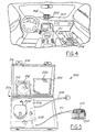
- a kit 200 is shown in Figs 4 and 5 for conveniently carrying out the squeak and rattle identification method.
- the kit has a portable case 202 which contains a CD player 204 mounted in a support panel 206.
- the CD player 204 is connected to an amplifier 208, preferably stored below the panel 206, which in turn is connected to a vibration generating device, or tactile transducer, such as a base shaker 210.
- the base shaker 210 also known as an inertial actuator, typically consists of a mass that is moved back and forth along an axis using an electromagnetic voice coil. The back and forth movement of the mass generates inertial forces that are transmitted to the external casing through the shaft.
- the base shaker 210 has a retractable cord 211 which permits the base shaker to be positioned at a predetermined distance from the portable case 202, as best seen in Fig. 4
- the kit 200 has a sleeve 212 on an inner surface 214 of the lid 216 for receiving a CD 218.
- the CD 218 has calibration signals stored on several tracks corresponding to various components in the vehicle which are known to possibly produce squeak and rattle. The calibration signals are determined by the above described method.
- a second sleeve 220 contains a dual sided tape 222 (Fig. 5) for attaching the base shaker to a target component, such as to the instrument panel 223 of a vehicle (Fig. 4). One side of the tape attaches to the bottom of the base-shaker and the other side attaches to the instrument panel. Other attachment means may also be used, such as clamps, wires, and single-sided tape.
- the kit 200 has a power cord 224 which connects to an external source for supplying power to the CD player 204 and amplifier 208. Additionally, the kit preferably has a battery, stowable beneath the panel 206, to supply power to the various kit components.
- signal generation drive means can be used other than the CD player, such as a magnetic tape player.
- a magnetic cassette tape with the appropriate calibration signals stored thereon would be played on the tape player.
- a personal computer (PC) could also be used to store and send the appropriate signals to the amplifier.
- Data acquisition can be accomplished with a portable computer configured with an appropriate data acquisition card.
- the data acquisition card may have, for example, two 12-bit analog-to-digital converters that can be simultaneously sampled with a predetermined input range, for example, plus or minus 2.5 volts.
- the system also has two 12-bit digital-2-analog converters with a plus or minus 5 volt output range. These inputs are used for recording time signals to compute a frequency response function (FRF) between the excitation transducer, e.g. base shaker, and an accelerometer, while the output signal is used to generate the signals needed for various measurements (Fig. 2).
- FPF frequency response function
- a signal generator is also implemented on the PC, which can be a random signal generator or a arbitrary time signal loaded from a previously saved file.
- Various signal sampling parameters such as the sampling frequency, the length of time signal, the input channel, and the file format to save the time signals, can be selected through software, preferably using graphical user interface (GUI).
- GUI graphical user interface
Landscapes
- Physics & Mathematics (AREA)
- General Physics & Mathematics (AREA)
- Engineering & Computer Science (AREA)
- Automation & Control Theory (AREA)
- Measurement Of Mechanical Vibrations Or Ultrasonic Waves (AREA)
- Fittings On The Vehicle Exterior For Carrying Loads, And Devices For Holding Or Mounting Articles (AREA)
- Apparatuses For Generation Of Mechanical Vibrations (AREA)
Claims (7)
- Kit zur Diagnose von Geräuschen von einer Zielkomponente einer aus mehreren Komponenten bestehenden Einheit, welcher Kit folgendes beinhaltet:dadurch gekennzeichnet, daßVibrationserzeugermittel (210);Treibermittel (204, 208) zum Betreiben der Vibrationserzeugermittel; undSteuerungsmittel (218) zur Steuerung der Vibrationserzeugermittel (210) über die Treibermittel (204, 208), so daß ein Satz vorgegebener, geräuscherzeugender Schwingungen in der Zielkomponente erzeugt wird,die Vibrationserzeugermittel (210) in der Lage sind, selektiv an unterschiedlichen Zielkomponenten der aus mehreren Komponenten bestehenden Einheit angebracht zu werden.
- Kit nach Anspruch 1, worin die Vibrationserzeugermittel (210) einen piezoelektrischen Trägheitsantrieb oder Bassrüttler aufweisen, der an der ausgewählten Komponente befestigt wird.
- Kit nach Anspruch 2, worin die Befestigungsmittel beidseitig klebendes Klebeband beinhalten.
- Kit nach einem beliebigen der Ansprüche 1 bis 3, worin die Treibermittel (204, 208) ein CD-Laufwerk (204) beinhalten.
- Kit nach einem beliebigen der Ansprüche 1 bis 4, worin die Steuermittel (218) einen vorgegebenen Satz von Steuersignalen beinhalten, die von den Treibermitteln (204, 208) gelesen und in elektrische Signale gewandelt werden, die an die Vibrationserzeugermittel (210) gesendet werden, so daß geräuscherzeugende Schwingungen in der Zielkomponente erzeugt werden.
- Kit nach Anspruch 5, worin der vorgegebene Satz Steuersignale einen Satz Kalibriersignale beinhaltet, die mit einem Reziprokfilter in Verbindung mit einem Satz von Schwingungsdaten an einer vorgegebenen Schwingungsmeßstelle der Zielkomponente bestimmt werden, wenn die Einheit aus mehreren Komponenten in Schwingung gesetzt wird.
- Kit nach einem beliebigen der vorangehenden Ansprüche, worin die Treibermittel (204, 208) und die Steuerungsmittel (218) eigenständig in einem tragbaren Koffer (202) untergebracht sind, der außerdem ausgelegt ist, die Vibrationserzeugermittel (210) aufzunehmen, wenn der Koffer transportiert wird.
Applications Claiming Priority (2)
| Application Number | Priority Date | Filing Date | Title |
|---|---|---|---|
| US09/111,680 US6116091A (en) | 1998-07-08 | 1998-07-08 | System for diagnosing unexpected noise in a multi-component assembly |
| US111680 | 1998-07-08 |
Publications (3)
| Publication Number | Publication Date |
|---|---|
| EP0971217A2 EP0971217A2 (de) | 2000-01-12 |
| EP0971217A3 EP0971217A3 (de) | 2002-07-10 |
| EP0971217B1 true EP0971217B1 (de) | 2005-12-14 |
Family
ID=22339882
Family Applications (1)
| Application Number | Title | Priority Date | Filing Date |
|---|---|---|---|
| EP99305337A Expired - Lifetime EP0971217B1 (de) | 1998-07-08 | 1999-07-06 | Diagnosesystem für unerwarteten Rausch in einer Vielfach-komponent-Anordnung |
Country Status (4)
| Country | Link |
|---|---|
| US (1) | US6116091A (de) |
| EP (1) | EP0971217B1 (de) |
| JP (1) | JP2000039382A (de) |
| DE (1) | DE69928870T2 (de) |
Families Citing this family (13)
| Publication number | Priority date | Publication date | Assignee | Title |
|---|---|---|---|---|
| GB2394292B (en) * | 2002-10-16 | 2006-05-24 | Roger William Fox | Apparatus for use in finding the location of noises in objects |
| US20040090070A1 (en) * | 2002-11-13 | 2004-05-13 | United Global Sourcing Incorporated | Manually-operated device for supplying electrical power to mobile telephones, flashlights, toys, or other battery-operated electrical devices |
| KR20050039352A (ko) * | 2003-10-24 | 2005-04-29 | 현대자동차주식회사 | 차량용 파워 트레인의 래틀 소음 분석방법 |
| KR100727488B1 (ko) * | 2004-11-05 | 2007-06-13 | 국방과학연구소 | 충격 응답 스펙트럼이 나타나는 시간들의 차이가 짧은충격파형의 합성 방법 및 충격 응답 내역을 구하는 디지털필터와 그 응용 |
| US20070080264A1 (en) * | 2005-09-28 | 2007-04-12 | Richard Kukucka | Articulating lift gate speakers |
| DE102006032910A1 (de) * | 2006-07-15 | 2008-01-24 | Conti Temic Microelectronic Gmbh | Verfahren zur Bewertung mechanischer Elemente in einem Kraftfahrzeug |
| GB2449663A (en) * | 2007-05-30 | 2008-12-03 | Stuart Wright | Locating rattles with sound waves |
| CN108139299B (zh) * | 2015-10-16 | 2021-04-13 | 巴里理工大学 | 用于确定道路或轨道车辆的模态参数并间接表征道路或轨道轮廓的方法 |
| KR101865897B1 (ko) * | 2016-09-06 | 2018-06-08 | 창원대학교 산학협력단 | 서포트 벡터 머신을 이용한 회전체 수명 진단방법 |
| US10152296B2 (en) | 2016-12-28 | 2018-12-11 | Harman International Industries, Incorporated | Apparatus and method for providing a personalized bass tactile output associated with an audio signal |
| US11016002B2 (en) * | 2018-10-30 | 2021-05-25 | Ford Global Technologies, Llc | In situ vibration-based verification of vehicle doors |
| CN111366375A (zh) * | 2020-03-05 | 2020-07-03 | 三一汽车起重机械有限公司 | 基于音频和图像处理的车辆噪声和振动诊断方法和系统 |
| DE102020211877A1 (de) * | 2020-09-23 | 2022-03-24 | Robert Bosch Gesellschaft mit beschränkter Haftung | Verfahren und Vorrichtung zum Detektieren eines Zustandes eines Fahrzeugs |
Family Cites Families (19)
| Publication number | Priority date | Publication date | Assignee | Title |
|---|---|---|---|---|
| US3695098A (en) * | 1970-08-27 | 1972-10-03 | Garlock Inc | Method and apparatus for isolating and measuring vehicle noise |
| US3748896A (en) * | 1972-01-20 | 1973-07-31 | Chicago Pneumatic Tool Co | Vibrator unit for testing a motor vehicle for rattles and squeaks |
| US3844175A (en) * | 1973-02-26 | 1974-10-29 | E Hixson | Noise source level detection |
| DE2730914A1 (de) * | 1977-07-08 | 1979-01-25 | Daimler Benz Ag | Verfahren zur simulation dynamischer belastungen und vorrichtung zur durchfuehrung derselben |
| JPS5938621A (ja) * | 1982-08-27 | 1984-03-02 | Nissan Motor Co Ltd | 振動分析装置 |
| GB2134286B (en) * | 1983-01-26 | 1986-05-14 | Schlumberger Electronics | Apparatus for and method of random vibration control |
| US4989158A (en) * | 1988-12-15 | 1991-01-29 | Schlumberger Technologies Limited | Vibration control system |
| US5275388A (en) * | 1991-11-26 | 1994-01-04 | Honda Giken Kogyo Kabushiki Kaisha | Vibration control system |
| JP3107903B2 (ja) * | 1992-04-24 | 2000-11-13 | キヤノン株式会社 | 振動波モータのための駆動装置 |
| US5313407A (en) * | 1992-06-03 | 1994-05-17 | Ford Motor Company | Integrated active vibration cancellation and machine diagnostic system |
| JP3345930B2 (ja) * | 1993-01-06 | 2002-11-18 | 日産自動車株式会社 | アクティブコントロール装置 |
| EP0693212B1 (de) * | 1993-04-07 | 1999-12-08 | Noise Cancellation Technologies, Inc. | Hybrides analog/digital schwingungsunterdrückungssystem |
| GB2287536A (en) * | 1994-03-09 | 1995-09-20 | Ford Motor Co | Identification of vibration induced noises in vehicles |
| JP2899205B2 (ja) * | 1994-03-16 | 1999-06-02 | 本田技研工業株式会社 | 車両用能動振動騒音制御装置 |
| JP3572486B2 (ja) * | 1994-03-25 | 2004-10-06 | 本田技研工業株式会社 | 振動騒音制御装置 |
| US5418858A (en) * | 1994-07-11 | 1995-05-23 | Cooper Tire & Rubber Company | Method and apparatus for intelligent active and semi-active vibration control |
| US5479823A (en) * | 1994-11-03 | 1996-01-02 | Chrysler Corporation | Method and apparatus for inducing audio vibrations |
| US5535131A (en) * | 1995-08-22 | 1996-07-09 | Chrysler Corporation | System for analyzing sound quality in automobile using musical intervals |
| US5641904A (en) * | 1995-12-07 | 1997-06-24 | Ford Motor Company | Method and apparatus for detecting drive line system imbalance |
-
1998
- 1998-07-08 US US09/111,680 patent/US6116091A/en not_active Expired - Fee Related
-
1999
- 1999-07-06 DE DE69928870T patent/DE69928870T2/de not_active Expired - Fee Related
- 1999-07-06 JP JP11191617A patent/JP2000039382A/ja active Pending
- 1999-07-06 EP EP99305337A patent/EP0971217B1/de not_active Expired - Lifetime
Also Published As
| Publication number | Publication date |
|---|---|
| DE69928870D1 (de) | 2006-01-19 |
| EP0971217A3 (de) | 2002-07-10 |
| DE69928870T2 (de) | 2006-07-13 |
| JP2000039382A (ja) | 2000-02-08 |
| EP0971217A2 (de) | 2000-01-12 |
| US6116091A (en) | 2000-09-12 |
Similar Documents
| Publication | Publication Date | Title |
|---|---|---|
| US6116091A (en) | System for diagnosing unexpected noise in a multi-component assembly | |
| US6101882A (en) | Method for determining and reproducing noise inducing vibrations in a multi-component assembly | |
| CN1619951B (zh) | 具有振动传感器的车辆音频控制器 | |
| JPH0550696B2 (de) | ||
| Bettella et al. | Investigation of automotive creep groan noise with a distributed-source excitation technique | |
| KR960011152B1 (ko) | 능동 진동제어 시스템 및 이를 포함하는 내연기관 구동차량 | |
| US6386039B1 (en) | Method and apparatus for determining the acoustic spatial characteristics particularly of a vehicle occupant compartment in a motor vehicle | |
| CN117636835A (zh) | 主动降低车内噪声的方法、装置、设备及介质 | |
| US7587057B2 (en) | Vibroacoustic emulator | |
| JP3959624B2 (ja) | 模擬振動発生装置及び方法 | |
| JP2003216163A (ja) | 騒音制御装置 | |
| US6035720A (en) | Method and device for simulating an impression which is subjectively perceived by an occupant of a vehicle in particular of passenger car when the vehicle is being operated | |
| US5491753A (en) | Method and device for testing for audio induced sympathetic buzzes | |
| US6549628B1 (en) | Method for determining and optionally eliminating a disturbing noise subjectively perceived by an operator | |
| JPH1032891A (ja) | エンジン用アクティブマウント付き車両 | |
| Putner et al. | Investigation of NVH phenomena at electric vehicles | |
| CN119299892A (zh) | 针对车载音响补偿的降噪方法、系统、设备和存储介质 | |
| US5479823A (en) | Method and apparatus for inducing audio vibrations | |
| JPH06282281A (ja) | 車両用振動制御装置 | |
| US12183317B2 (en) | Call environment generation method, call environment generation apparatus, and program | |
| JPH06288872A (ja) | ブレーキ振動評価方法 | |
| Riemann et al. | Interactive auralization of powertrain sounds using measured and simulated excitation | |
| Russell et al. | Towards an objective estimate of the subjective reaction to diesel engine noise | |
| JP4002498B2 (ja) | 車室内音シミュレート装置および次数成分除去フィルタ | |
| KR100224182B1 (ko) | 자동차 파워트레인의 소음 측정 장치 및 방법 |
Legal Events
| Date | Code | Title | Description |
|---|---|---|---|
| PUAI | Public reference made under article 153(3) epc to a published international application that has entered the european phase |
Free format text: ORIGINAL CODE: 0009012 |
|
| AK | Designated contracting states |
Kind code of ref document: A2 Designated state(s): AT BE CH CY DE DK ES FI FR GB GR IE IT LI LU MC NL PT SE |
|
| AX | Request for extension of the european patent |
Free format text: AL;LT;LV;MK;RO;SI |
|
| PUAL | Search report despatched |
Free format text: ORIGINAL CODE: 0009013 |
|
| AK | Designated contracting states |
Kind code of ref document: A3 Designated state(s): AT BE CH CY DE DK ES FI FR GB GR IE IT LI LU MC NL PT SE |
|
| AX | Request for extension of the european patent |
Free format text: AL;LT;LV;MK;RO;SI |
|
| RIC1 | Information provided on ipc code assigned before grant |
Free format text: 7G 01M 7/00 A, 7G 01M 17/007 B |
|
| 17P | Request for examination filed |
Effective date: 20021227 |
|
| D17P | Request for examination filed (deleted) | ||
| AKX | Designation fees paid |
Designated state(s): DE FR GB |
|
| R17P | Request for examination filed (corrected) |
Effective date: 20021227 |
|
| 17Q | First examination report despatched |
Effective date: 20031028 |
|
| GRAP | Despatch of communication of intention to grant a patent |
Free format text: ORIGINAL CODE: EPIDOSNIGR1 |
|
| GRAS | Grant fee paid |
Free format text: ORIGINAL CODE: EPIDOSNIGR3 |
|
| GRAA | (expected) grant |
Free format text: ORIGINAL CODE: 0009210 |
|
| RAP1 | Party data changed (applicant data changed or rights of an application transferred) |
Owner name: FORD GLOBAL TECHNOLOGIES, LLC |
|
| AK | Designated contracting states |
Kind code of ref document: B1 Designated state(s): DE FR GB |
|
| REG | Reference to a national code |
Ref country code: GB Ref legal event code: FG4D |
|
| REF | Corresponds to: |
Ref document number: 69928870 Country of ref document: DE Date of ref document: 20060119 Kind code of ref document: P |
|
| RAP2 | Party data changed (patent owner data changed or rights of a patent transferred) |
Owner name: FORD GLOBAL TECHNOLOGIES, LLC. |
|
| ET | Fr: translation filed | ||
| PLBE | No opposition filed within time limit |
Free format text: ORIGINAL CODE: 0009261 |
|
| STAA | Information on the status of an ep patent application or granted ep patent |
Free format text: STATUS: NO OPPOSITION FILED WITHIN TIME LIMIT |
|
| 26N | No opposition filed |
Effective date: 20060915 |
|
| PGFP | Annual fee paid to national office [announced via postgrant information from national office to epo] |
Ref country code: FR Payment date: 20090708 Year of fee payment: 11 |
|
| PGFP | Annual fee paid to national office [announced via postgrant information from national office to epo] |
Ref country code: GB Payment date: 20090612 Year of fee payment: 11 Ref country code: DE Payment date: 20090730 Year of fee payment: 11 |
|
| GBPC | Gb: european patent ceased through non-payment of renewal fee |
Effective date: 20100706 |
|
| REG | Reference to a national code |
Ref country code: FR Ref legal event code: ST Effective date: 20110331 |
|
| PG25 | Lapsed in a contracting state [announced via postgrant information from national office to epo] |
Ref country code: DE Free format text: LAPSE BECAUSE OF NON-PAYMENT OF DUE FEES Effective date: 20110201 |
|
| REG | Reference to a national code |
Ref country code: DE Ref legal event code: R119 Ref document number: 69928870 Country of ref document: DE Effective date: 20110201 |
|
| PG25 | Lapsed in a contracting state [announced via postgrant information from national office to epo] |
Ref country code: FR Free format text: LAPSE BECAUSE OF NON-PAYMENT OF DUE FEES Effective date: 20100802 |
|
| PG25 | Lapsed in a contracting state [announced via postgrant information from national office to epo] |
Ref country code: GB Free format text: LAPSE BECAUSE OF NON-PAYMENT OF DUE FEES Effective date: 20100706 |