EP0970842A1 - Dispositif de fixation pour un siège de sécurité pour enfant - Google Patents
Dispositif de fixation pour un siège de sécurité pour enfant Download PDFInfo
- Publication number
- EP0970842A1 EP0970842A1 EP99850108A EP99850108A EP0970842A1 EP 0970842 A1 EP0970842 A1 EP 0970842A1 EP 99850108 A EP99850108 A EP 99850108A EP 99850108 A EP99850108 A EP 99850108A EP 0970842 A1 EP0970842 A1 EP 0970842A1
- Authority
- EP
- European Patent Office
- Prior art keywords
- mounting means
- seat
- means according
- chassis
- lock hook
- Prior art date
- Legal status (The legal status is an assumption and is not a legal conclusion. Google has not performed a legal analysis and makes no representation as to the accuracy of the status listed.)
- Granted
Links
Images


Classifications
-
- B—PERFORMING OPERATIONS; TRANSPORTING
- B60—VEHICLES IN GENERAL
- B60N—SEATS SPECIALLY ADAPTED FOR VEHICLES; VEHICLE PASSENGER ACCOMMODATION NOT OTHERWISE PROVIDED FOR
- B60N2/00—Seats specially adapted for vehicles; Arrangement or mounting of seats in vehicles
- B60N2/24—Seats specially adapted for vehicles; Arrangement or mounting of seats in vehicles for particular purposes or particular vehicles
- B60N2/26—Seats specially adapted for vehicles; Arrangement or mounting of seats in vehicles for particular purposes or particular vehicles for children
- B60N2/28—Seats readily mountable on, and dismountable from, existing seats or other parts of the vehicle
- B60N2/2857—Seats readily mountable on, and dismountable from, existing seats or other parts of the vehicle characterised by the peculiar orientation of the child
- B60N2/286—Seats readily mountable on, and dismountable from, existing seats or other parts of the vehicle characterised by the peculiar orientation of the child forward facing
-
- B—PERFORMING OPERATIONS; TRANSPORTING
- B60—VEHICLES IN GENERAL
- B60N—SEATS SPECIALLY ADAPTED FOR VEHICLES; VEHICLE PASSENGER ACCOMMODATION NOT OTHERWISE PROVIDED FOR
- B60N2/00—Seats specially adapted for vehicles; Arrangement or mounting of seats in vehicles
- B60N2/24—Seats specially adapted for vehicles; Arrangement or mounting of seats in vehicles for particular purposes or particular vehicles
- B60N2/26—Seats specially adapted for vehicles; Arrangement or mounting of seats in vehicles for particular purposes or particular vehicles for children
- B60N2/28—Seats readily mountable on, and dismountable from, existing seats or other parts of the vehicle
- B60N2/2821—Seats readily mountable on, and dismountable from, existing seats or other parts of the vehicle having a seat and a base part
-
- B—PERFORMING OPERATIONS; TRANSPORTING
- B60—VEHICLES IN GENERAL
- B60N—SEATS SPECIALLY ADAPTED FOR VEHICLES; VEHICLE PASSENGER ACCOMMODATION NOT OTHERWISE PROVIDED FOR
- B60N2/00—Seats specially adapted for vehicles; Arrangement or mounting of seats in vehicles
- B60N2/24—Seats specially adapted for vehicles; Arrangement or mounting of seats in vehicles for particular purposes or particular vehicles
- B60N2/26—Seats specially adapted for vehicles; Arrangement or mounting of seats in vehicles for particular purposes or particular vehicles for children
- B60N2/28—Seats readily mountable on, and dismountable from, existing seats or other parts of the vehicle
- B60N2/2887—Fixation to a transversal anchorage bar, e.g. isofix
- B60N2/2893—Fixation to a transversal anchorage bar, e.g. isofix coupled to the seat sub-frame
Definitions
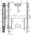
- the invention relates to a mounting means for a child seat intended to be mounted facing forward on a vehicle seat with the seat back of the child seat placed against the seat back of the vehicle seat, comprising two connectors for co-operation with a fixedly mounted anchoring means available between the seat bottom and seat back of the vehicle seat.
- the forward edge of the child seat will be located at different forward positions on the seat bottom of the vehicle seat depending on the dimensions and shape of the vehicle seat.
- the child seat will pivot with the anchoring means as pivot axis the seat bottom of the child seat being pressed against the seat bottom of the vehicle seat.
- An object of the invention is to provide a mounting means of the kind referred to above which eliminates said disadvantages by the fact that the child seat at mounting thereof on the vehicle seat will not at all slide on the seat bottom of the vehicle seat and the force acting against the seat at collision or sudden braking always will be received at one and the same position as near the forward end of the seat bottom of the vehicle seat as possible independent of the position of the child seat on the vehicle seat.
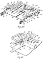
- FIGS. 1 and 2 there is disclosed diagrammatically a child seat 10 having a seat bottom 10A and a seat back 10B, and a vehicle seat 11 having a seat bottom 11A and a seat back 11B. Between the seat bottom 11A and the seat back 11B two brackets 12 (type ISOFIX) are provided which are securely mounted in the vehicle and form anchoring means for the child seat 10. This is shown in mounting position in FIG. 1 and in position of use in FIG. 2 and is provided with the mounting means according to the invention which is indicated generally at 13.
- brackets 12 type ISOFIX
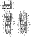
- the mounting means comprises a chassis which consists of a bottom metal sheet 14 with edge flanges 15 bent upwards at right angles, and two U-shaped metal sheet sections 16 which are welded to the inside of one and the other, respectively, of the edge flanges 15, cf. FIG. 10, so that the bottom metal sheet and the metal sheet sections form two box girders extending along opposite edges of the bottom metal sheet.
- a shidable carrier which comprises a transverse box girder 17 and two U-shaped sections 18 attached each to one end of the box girder 17 and extending at right angles to said girder, is displaceably guided at the U-shaped sections on the box girders formed by the edge flanges 15 and the metal sheet sections 16, cf.
- FIG. 10 which thus form guide rails for the slidable carrier.
- Two helical tension springs 20 are engaged between two lugs 19 angled upwards from the bottom metal sheet 14, and the box girder 17.
- the child seat 10 which can be of a known construction and can comprise a plastic shell with a soft resilient covering shall be attached to the slidable carrier at the seat bottom 10A so that the fastening means forms an undercarriage of the child seat as will be seen from FIGS. 1 and 2.
- a handle 21 shall be pivotally mounted by means of a shaft extending through an aperture 22 in the handle, and this handle is constructed to engage at a projection 23 on the handle with a saw-toothed rail 24 which is connected to the upper side of the bottom metal sheet 14.
- a handle opening 25 is provided in order to facilitate handling of the child seat provided with the mounting means.
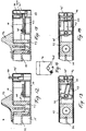
- the connector comprises a lock hook 28 which is pivoted on a pin 29 and is biased by means of a shackle spring 30 for pivotal movement clock-wise as seen in FIGS. 9 and 11.
- the lock hook 28 forms a notch 31 for engagement with the bracket 12 and a notch 32 for engagement with a latch member 33 which is displaceably guided in a flap 34 struck from the edge flange 15, and is biased by a helical spring 35 against the lock hook engaging the edge surface thereof.
- a rail 36 which is displaceably guided in the flap 34 and is biased against the lock hook 28 by means of a compression spring 37, has an angled end 36A engaging displaceably in an oblique groove 38 on a blocking member 39 which is displaceably guided in the transverse direction of the box girder 15, 16 by means of flaps 40 struck from the edge flange 15.
- the blocking member 39 With the rail 36 in the shown position the blocking member 39 is kept in a projecting position, FIG. 9, and is the projecting portion thereof located in front of the end of the U-shaped section 18 forming part of the slideable carrier, so that the carrier and thus the child seat cannot be displaced to the left in relation to the chassis as seen in FIGS. 3-5 and 9 even if the latch means 21-24 should be actuated to released position.
- the connector 27 is enclosed by a snapped-on plastic cover 40'.
- the child seat is now lifted to a position over the vehicle seat and the lock hooks 28 thereof are moved against the brackets 12 which are received in the notches 31.
- a notch 41 which diverges towards the mouth thereof is provided in the box girder 15, 16 and in the cover 40' in order to facilitate the movement of the lock hook 28 onto the bracket 12. This operation can easily be performed since the connectors can be freely observed behind the withdrawn child seat.
- the lock hook 28 is pivoted to lock position counter-clockwise as seen in FIG. 9 against the bias of the shackle spring 30 so that the latch member 33 can snap into the notch 32 in order to latch the lock hook in the lock position thereof.
- the child seat is pivoted onto the seat bottom 11A of the vehicle seat 11 to the position in FIG. 1 in which the child seat rests stationarily against the seat bottom 11A at the bottom metal sheet 14.
- the child seat is now in the position of use on the vehicle seat, and it has been brought to this position without sliding on the seat bottom of the vehicle seat because the displacement from the position in FIG. 1 to the position according to FIG. 2 takes place between the slidable carrier and the stationary chassis.
- each box girder 15, 16 For decoupling the child seat from the vehicle seat there is provided on each box girder 15, 16 at the end which is opposite to the connector 27 an operating member 42 which is displaceable along the box girder 15, 16 and engages a block 43 displaceably mounted in the box girder said block being connected with the latch member 33 by means of a connecting rod 44.
- the operating member 42 By displacement of the operating member 42 to the right as seen in FIG. 7 the latch member 33 is withdrawn from the notch 32 against the bias of the spring 35 so that the lock hook 28 can be disengaged from the bracket 12.
- the slidable carrier When the latch 21-24 is disengaged the slidable carrier and thus the child seat will be kept by the springs 20 in the position shown in FIG. 2 in relation to the chassis the connectors 27 being enclosed by the U-shaped sections 18 as will be best seen from FIGS 6-8.
- the slidable carrier When the child seat shall be mounted to the vehicle seat the slidable carrier should initially be in this position which is also a shipping position so that the connectors cannot damage the vehicle for example on the seat and the instrument panel when the child seat is handled inside the vehicle.
- the mounting means comprises an indicating means shown in FIGS. 12-16.
- a plastic housing 45 is mounted to the end of the box girder 15, 16 and in this housing there is provided an indicator 46 guided for displacement vertically said indicator having at the lower edge thereof a V-shaped notch 46A.
- Inside the box girder 15, 16 a cross-shaped element 47 is provided, which can be pivoted about a vertically projecting pin 48 integral with the plastic housing 45.
- the block 43 has a projection 49 which can be engaged with one cross arm of the element 47 while the stem of the cross-shaped element 47 has a projecting pin 50 extending into the plastic housing 45 and received by the notch 46A.
- the indicator 46 will now by gravity sink into the housing 45 while the cross-shaped element 47 by the movement of the pin 50 along one oblique surface of the notch 46A will be cammed to the centred position according to FIGS. 15 and 16. No part of the indicator 46 now projects from the box girder 15, 16. When it cannot be seen or felt that the indicator projects from the box girder 15, 16 the connector accordingly is in the latch position thereof.
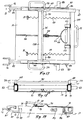
- the chassis and the slidable carrier principally are constructed in the same manner as described above.
- the same references therefore have been used on those parts which correspond to each other in the two embodiments.
- the slidable carrier comprises two transverse box girders 17A and 17B the tension springs 20 being engaged between the lugs 19 and the box girder 17A.
- a handle 51 is connected to the bottom metal sheet 14 to facilitate the handling of the child seat provided with the mounting means.
- the child seat shall be connected to the slidable carrier as described above.
- a handle 52 is pivoted to angular brackets 53 which are mounted to the box girder 17A, and by means of a wire rope 54 is connected with a lock tooth 55 pivoted to the box girder 17B, said lock tooth being spring biased to engage a saw-toothed rail 56 which is mounted to the upper side of the bottom metal sheet 14.
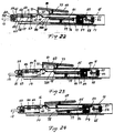
- a connector 58 is connected by means of rivets 57 said connector comprising a lock hook 59 which is pivoted on a pin 60 and is biased by means of a shackle spring for swinging movement clockwise as seen for example in FIG. 22.
- the lock hook 59 forms a notch 62 for engagement with one of the brackets 12 and a notch 63 for engagement with a latch member 64 which is displaceably guided in a struck flap 65 and is biased by means of a helical spring 66 to engage the edge surface of the lock hook at one end thereof.
- a metal sheet element 67 is riveted said element having an aperture 68 in a bent-up central portion of the metal sheet element. This bent-up portion engages or is located adjacent the lower side of the upper flange of the U-shaped section 16.
- a latch clasp 69 is pivoted at one end thereof on a lug 70 formed by the bent-up edge flange 15 the other end of the latch clasp being shaped as a hook 71 located in register with an aperture 72 in the upper flange of the U-shaped section 16 said aperture being dimensioned in order that the hook can be passed therethrough.
- the hook cannot pass through the aperture with the latch member 67 in engagement with the lock hook 59 outside the notch 63 as shown in FIG. 22 because the aperture 68 in the metal sheet element 67 then is displaced in relation to the aperture 72 so that the metal sheet element prevents the passage of the hook 71.
- the latch clasp is biased by means of a compression spring 73 engaged between the clasp and the upper flange of the U-shaped section 16, in order to be kept in the raised position shown in FIGS. 19, 22 and 23.
- a handle 74 projecting from the side of the chassis is provided on the latch clasp, and the latch clasps provided at one and the other side of the slidable carrier are interconnected by means of a rod 75.
- a blocking clasp 76 is pivotally mounted at one end thereof at 77 while the other end forms a hook 78.
- the blocking clasp is biased by means of a compression spring 79 engaged between the clasp and the lower flange of the U-shaped section 16 said spring maintaining the blocking clasp in a raised position according to FIGS.
- the latch clasp 69 at the lower side thereof has a projection 81 which can be engaged with the hook 78 at lowering of the latch clasp when this is possible.
- the child seat When the child seat shall be locked to the vehicle seat it is held above and close to the vehicle seat with the slidable carrier and thus the child seat withdrawn in relation to the chassis and locked by means of the hook 78 in the position shown in FIGS. 17, 19 and 23 the springs 20 being tensioned.
- the latch member 64 is located outside the notch 63. Therefore, the blocking clasp cannot be pressed down in order to release the slidable carrier by lowering the latch clasp 69 and thus engagement of the projection 81 with the hook 78 because the passage of the hook 71 through the aperture 72 is blocked by the metal sheet element 67.
- the child seat is now moved with the lock hooks 59 against the respective brackets 12 which are received by the respective notches 62, FIG. 22.
- a notch 81' diverging towards the mouth thereof is provided in a cover 82 enclosing the connector, in order to facilitate guiding of the lock hook 59 onto the bracket 12.
- This operation can easily be performed because one has free view of the connectors behind the withdrawn child seat.
- the lock hook 59 is swung to locking position counter-clockwise as seen in FIG. 22 against the bias of the shackle spring 61 so that the latch member 64 can snap into the notch 63 in order to latch the lock hook in the locking position thereof, FIG. 23.
- a clicking sound is heard.
- the child seat after connection is swung downwards onto the seat bottom 11A of the vehicle seat 11 to the position in FIG. 1 in which the child seat rests stationarily at the bottom metal sheet 14 against the seat bottom 11A.
- the mounting means is now in the position according to FIGS. 25 and 26.
- the child seat has been brought to the position of use without sliding on the seat bottom of the vehicle seat because the displacement from the position in FIG. 1 to the position according to FIG. 2 takes place between the slidable carrier and the stationary chassis.
- each box girder 15, 16 adjacent the end which is opposite to the lock hook 59 an operating handle 83 which is displaceable along the box girder 15, 16 an engages in a block 84 displaceably mounted in the box girder said block being connected by means of a coupling rod 85 with the metal sheet element 67 and thus with the latch member 64.
- the connecting rod passes through a slot 78A in the hook 78.
- the handle 51 on the bottom metal sheet 14 is grasped by one hand and the handle 52 on the slidable carrier is grasped by the other hand in order to disengage the lock tooth 55 from the saw-toothed rail 56 on the bottom metal sheet 14.
- the slidable carrier and the child seat mounted thereon then can be withdrawn on the chassis the blocking clasp 76 being raised by the spring 79 and the hook 78 projecting upwards through the aperture 50 and blocking the return of the slidable carrier.
- the mounting means then is again in the position according to FIGS. 17, 19 and 22.
- the fastening means according to the second embodiment of the invention has an indicating mechanism.
- a plastic housing 86 is mounted to the outside of the flange 15 in the right end of the box girder 15, 16, and an indicator 87 is displaceably guided in this plastic housing.
- the indicator is spring biased to a withdrawn position inside the housing but can be displaced against the spring bias to a projected position.
- a transmission element 88 is pivotally mounted inside the box girder 15, 16 .
- the block 84 has a projection 89 which can be engaged with the element 88 which extends into the plastic housing 86 wherein it is received in an oblique slot in the indicator 87.
- the indicator 87 will now be displaced into the housing 86 under the spring bias while the transmission element 88 moves along the oblique slot in the indicator 87. No part of the indicator 76 projects now from the box girder 15, 16. When it is not possible to see or feel that the indicator projects from the box girder 15, 16 the connector 58 accordingly is in the latched position thereof.
- the fastening means therefore has a built-in "change-the-mind function" in order to make it possible that the slidable carrier with the child seat under said conditions is returned to the position according to FIGS. 25 and 26.
- a push-button 90 is provided which projects at the inside of the box girder 15, 16 through a slot 91 in the web of the U-shaped section 16.
- the button being depressed it is possible to bring the blocking clasp 76 to open position independent of the latch clasp 69 so that the slidable carrier with the child seat can be displaced to the left as seen in FIG. 22.
- the seat back of the child seat can be pressed against the seat back of the vehicle seat in the position shown in FIG. 2 and be locked there by means of the latch means 55, 56.
- the child seat is then anchored in the vehicle by means of the three-point safety belt provided for the vehicle seat.
- the buttons 90 can be interconnected such that the device will be more easy to use due to the fact that it is necessary to depress one button only.
Landscapes
- Engineering & Computer Science (AREA)
- Health & Medical Sciences (AREA)
- Child & Adolescent Psychology (AREA)
- General Health & Medical Sciences (AREA)
- Aviation & Aerospace Engineering (AREA)
- Transportation (AREA)
- Mechanical Engineering (AREA)
- Seats For Vehicles (AREA)
Applications Claiming Priority (4)
| Application Number | Priority Date | Filing Date | Title |
|---|---|---|---|
| SE9802437 | 1998-07-06 | ||
| SE9802437A SE9802437L (sv) | 1998-07-06 | 1998-07-06 | Fästanordning till bilbarnstol |
| SE9900217 | 1999-01-26 | ||
| SE9900217A SE9900217D0 (sv) | 1999-01-26 | 1999-01-26 | Fästanordning till bilbarnstol |
Publications (2)
| Publication Number | Publication Date |
|---|---|
| EP0970842A1 true EP0970842A1 (fr) | 2000-01-12 |
| EP0970842B1 EP0970842B1 (fr) | 2004-09-08 |
Family
ID=26663353
Family Applications (1)
| Application Number | Title | Priority Date | Filing Date |
|---|---|---|---|
| EP99850108A Expired - Lifetime EP0970842B1 (fr) | 1998-07-06 | 1999-06-18 | Dispositif de fixation pour un siège de sécurité pour enfant |
Country Status (3)
| Country | Link |
|---|---|
| EP (1) | EP0970842B1 (fr) |
| AT (1) | ATE275490T1 (fr) |
| DE (2) | DE69919942T2 (fr) |
Cited By (36)
| Publication number | Priority date | Publication date | Assignee | Title |
|---|---|---|---|---|
| NL1020764C2 (nl) * | 2002-06-05 | 2003-12-08 | Maxi Miliaan Bv | Kindervoertuigstoel voorzien van een onderstel en een met het onderstel verbonden stoel alsmede een dergelijk onderstel. |
| ES2196999A1 (es) * | 2002-03-14 | 2003-12-16 | Play Sa | Silla infantil para automoviles. |
| NL1023422C2 (nl) * | 2003-05-14 | 2004-11-16 | Maxi Miliaan Bv | Kindervoertuigstoel. |
| FR2864482A1 (fr) * | 2003-12-24 | 2005-07-01 | Peugeot Citroen Automobiles Sa | Dispositif de retenue d'un siege enfant |
| NL1028788C2 (nl) | 2005-04-18 | 2006-10-20 | Maxi Miliaan Bv | Onderstel alsmede kindervoertuigstoel voorzien van een dergelijk onderstel. |
| EP1839935A1 (fr) | 2006-03-23 | 2007-10-03 | SABELT S.p.A. | Dispositif d'ajustement par encliquetage entre un support mobile et une structure |
| EP1900567A1 (fr) | 2006-09-15 | 2008-03-19 | ARTSANA S.p.A. | Siège auto pour enfant avec attachement facile sur un siège automobile avec son système de fixation intégré |
| WO2008059036A1 (fr) * | 2006-11-16 | 2008-05-22 | Play, S. A. | Dispositif servant à manoeuvrer le système d'ancrage d'un siège pour bébé dans un véhicule automobile |
| EP1852300A3 (fr) * | 2006-03-10 | 2009-05-13 | Recaro GmbH & Co. KG | Siège enfant |
| WO2009062505A1 (fr) * | 2007-11-16 | 2009-05-22 | Seed A/S | Siège auto pour enfant devant être monté dans un véhicule |
| US7918001B2 (en) | 2008-03-31 | 2011-04-05 | Amsafe Commercial Products, Inc. | Multi-pivot latch assemblies |
| US8220118B2 (en) | 2008-03-31 | 2012-07-17 | Amsafe Commercial Products, Inc. | Multi-pivot latch assemblies |
| CN102785598A (zh) * | 2011-05-16 | 2012-11-21 | 明门香港股份有限公司 | 伸缩式连接装置及儿童汽车座椅 |
| GB2492270A (en) * | 2010-07-15 | 2012-12-26 | Wonderland Nurserygoods Hk Co | Child safety seat assembly |
| US8454089B2 (en) | 2010-01-11 | 2013-06-04 | Takata AG | Fastening device for a children's vehicle seat and children's vehicle seat |
| US8469400B2 (en) | 2009-02-23 | 2013-06-25 | Amsafe, Inc. (Phoenix Group) | Seat harness pretensioner |
| US8556344B2 (en) | 2010-07-15 | 2013-10-15 | Wonderland Nurserygoods Company Limited | Child safety seat assembly |
| EP2664491A1 (fr) * | 2012-05-15 | 2013-11-20 | Wonderland Nurserygoods Company Limited | Base de support pour un siège de sécurité pour enfant |
| US8646158B2 (en) | 2008-03-31 | 2014-02-11 | Amsafe Commercial Products, Inc. | Multi-pivot latch assemblies |
| US8713765B2 (en) | 2008-03-31 | 2014-05-06 | Amsafe Commercial Products, Inc. | Multi-pivot latch assemblies |
| CN104290622A (zh) * | 2013-07-19 | 2015-01-21 | 明门香港股份有限公司 | 安全座椅固定装置调整机构 |
| EP2853439A1 (fr) * | 2013-09-27 | 2015-04-01 | Wonderland Nurserygoods Company Limited | Dispositif de amortissement de siège et siège de sécurité pour véhicule comportant celui-ci |
| CN105034874A (zh) * | 2014-03-06 | 2015-11-11 | 明门香港股份有限公司 | 儿童安全座椅固定装置 |
| US9718427B2 (en) | 2013-07-19 | 2017-08-01 | Shield Restraint Sytems, Inc. | Latch device and anchor with swivel coupling |
| CN107107789A (zh) * | 2014-10-31 | 2017-08-29 | 瑞典雄霸安全制品有限公司 | 用于儿童交通工具座椅的可调节连接杆 |
| US9789791B2 (en) | 2013-10-23 | 2017-10-17 | Wonderland Nurserygoods Company Limited | Child safety seat |
| CN108099707A (zh) * | 2018-01-29 | 2018-06-01 | 上海沃雨电子科技有限公司 | Isofix滑轨机构 |
| CN108407682A (zh) * | 2018-05-15 | 2018-08-17 | 上海沃雨电子科技有限公司 | Isofix电动解锁机构 |
| WO2018172053A1 (fr) | 2017-03-22 | 2018-09-27 | Holmbergs Safety System Holding Ab | Barre de raccordement réglable pour un système de retenue pour enfant |
| CN109398180A (zh) * | 2018-12-18 | 2019-03-01 | 麦克英孚(宁波)婴童用品有限公司 | 一种isofix释锁机构及使用其的儿童安全座椅 |
| AT16780U1 (de) * | 2019-06-27 | 2020-08-15 | Trupe Eng Gmbh | Vorrichtung zur Fixierung eines Gegenstandes |
| CN111959357A (zh) * | 2020-08-28 | 2020-11-20 | 宁波宝贝第一母婴用品有限公司 | Isofix机构及安全座椅 |
| US10953847B2 (en) | 2018-03-06 | 2021-03-23 | Shield Restraint Systems | Height adjusters with anti-cinch features for occupant restraint systems |
| CN113581037A (zh) * | 2021-07-07 | 2021-11-02 | 好孩子儿童用品有限公司 | 儿童汽车安全座椅 |
| US11225220B2 (en) | 2018-04-04 | 2022-01-18 | Shield Restraint Systems, Inc. | Energy absorbing devices for use with webs |
| US11273790B2 (en) | 2018-03-06 | 2022-03-15 | Shield Restraint Systems, Inc. | Height adjusters with anti-cinch features for occupant restraint systems |
Families Citing this family (7)
| Publication number | Priority date | Publication date | Assignee | Title |
|---|---|---|---|---|
| US8444222B2 (en) | 2009-04-07 | 2013-05-21 | Amsafe Commercial Products, Inc. | Child safety seat attachment belt retractor system |
| DE202012101091U1 (de) | 2012-03-27 | 2012-05-31 | Curt Würstl Vermögensverwaltungs-Gmbh & Co. Kg | Befestigungsvorrichtung |
| US9022483B2 (en) | 2012-06-07 | 2015-05-05 | Shield Restraint Systems, Inc. | Seatbelt buckle tongue assembly |
| CN104760522B (zh) * | 2014-01-06 | 2017-03-29 | 宝钜儿童用品香港股份有限公司 | 儿童安全座 |
| CN104859495B (zh) | 2014-02-21 | 2017-04-12 | 宝钜儿童用品香港股份有限公司 | 儿童安全座 |
| US9358914B2 (en) | 2014-06-05 | 2016-06-07 | Amsafe, Inc. | Seatbelt anchor systems for aircraft and other vehicles, and associated methods of manufacture and use |
| WO2019236460A1 (fr) * | 2018-06-04 | 2019-12-12 | Safest Seats Llc | Fixations de verrou rigides rotatives pour une base de siège de voiture |
Citations (2)
| Publication number | Priority date | Publication date | Assignee | Title |
|---|---|---|---|---|
| EP0703113A2 (fr) * | 1994-08-25 | 1996-03-27 | BRITAX RÖMER Kindersicherheit GmbH | Siège de sécurité pour enfants dans des véhicules |
| DE29620067U1 (de) * | 1996-11-12 | 1997-02-13 | Kiddy Gmbh Auto Kindersitze | Kindersicherheitssitz |
-
1999
- 1999-06-18 DE DE69919942T patent/DE69919942T2/de not_active Expired - Lifetime
- 1999-06-18 DE DE0970842T patent/DE970842T1/de active Pending
- 1999-06-18 EP EP99850108A patent/EP0970842B1/fr not_active Expired - Lifetime
- 1999-06-18 AT AT99850108T patent/ATE275490T1/de not_active IP Right Cessation
Patent Citations (2)
| Publication number | Priority date | Publication date | Assignee | Title |
|---|---|---|---|---|
| EP0703113A2 (fr) * | 1994-08-25 | 1996-03-27 | BRITAX RÖMER Kindersicherheit GmbH | Siège de sécurité pour enfants dans des véhicules |
| DE29620067U1 (de) * | 1996-11-12 | 1997-02-13 | Kiddy Gmbh Auto Kindersitze | Kindersicherheitssitz |
Cited By (64)
| Publication number | Priority date | Publication date | Assignee | Title |
|---|---|---|---|---|
| ES2196999A1 (es) * | 2002-03-14 | 2003-12-16 | Play Sa | Silla infantil para automoviles. |
| EP1369293A1 (fr) * | 2002-06-05 | 2003-12-10 | Maxi Miliaan B.V. | Siège d'enfants pour véhicules à châssis et siège fixé au châssis, ainsi qu'un tel châssis |
| NL1020764C2 (nl) * | 2002-06-05 | 2003-12-08 | Maxi Miliaan Bv | Kindervoertuigstoel voorzien van een onderstel en een met het onderstel verbonden stoel alsmede een dergelijk onderstel. |
| NL1023422C2 (nl) * | 2003-05-14 | 2004-11-16 | Maxi Miliaan Bv | Kindervoertuigstoel. |
| EP1477356A1 (fr) * | 2003-05-14 | 2004-11-17 | Maxi Miliaan B.V. | Siège d'enfants pour véhicules |
| FR2864482A1 (fr) * | 2003-12-24 | 2005-07-01 | Peugeot Citroen Automobiles Sa | Dispositif de retenue d'un siege enfant |
| NL1028788C2 (nl) | 2005-04-18 | 2006-10-20 | Maxi Miliaan Bv | Onderstel alsmede kindervoertuigstoel voorzien van een dergelijk onderstel. |
| EP1714826A1 (fr) | 2005-04-18 | 2006-10-25 | Maxi Miliaan B.V. | Châssis et siège de véhicule d'enfant, pourvu d'un tel châssis |
| US7328946B2 (en) | 2005-04-18 | 2008-02-12 | Maxi Miliaan B.V. | Chassis as well as a child vehicle seat provided with such a chassis |
| CN1876434B (zh) * | 2005-04-18 | 2010-05-12 | 马西米利安公司 | 一种底盘以及一种设有这种底盘的儿童车辆座椅 |
| EP1852300A3 (fr) * | 2006-03-10 | 2009-05-13 | Recaro GmbH & Co. KG | Siège enfant |
| EP1839935A1 (fr) | 2006-03-23 | 2007-10-03 | SABELT S.p.A. | Dispositif d'ajustement par encliquetage entre un support mobile et une structure |
| EP1900567A1 (fr) | 2006-09-15 | 2008-03-19 | ARTSANA S.p.A. | Siège auto pour enfant avec attachement facile sur un siège automobile avec son système de fixation intégré |
| ES2315136A1 (es) * | 2006-11-16 | 2009-03-16 | Play, S.A. | Dispositivo de accionamiento del sistema de anclaje de un asiento infantil para automoviles. |
| WO2008059036A1 (fr) * | 2006-11-16 | 2008-05-22 | Play, S. A. | Dispositif servant à manoeuvrer le système d'ancrage d'un siège pour bébé dans un véhicule automobile |
| CN101573252B (zh) * | 2006-11-16 | 2013-03-20 | 普莱股份有限公司 | 汽车婴儿座椅的锚固系统 |
| WO2009062505A1 (fr) * | 2007-11-16 | 2009-05-22 | Seed A/S | Siège auto pour enfant devant être monté dans un véhicule |
| US7918001B2 (en) | 2008-03-31 | 2011-04-05 | Amsafe Commercial Products, Inc. | Multi-pivot latch assemblies |
| US8291555B2 (en) | 2008-03-31 | 2012-10-23 | Amsafe Commercial Products, Inc. | Multi-pivot latch assemblies |
| US8713765B2 (en) | 2008-03-31 | 2014-05-06 | Amsafe Commercial Products, Inc. | Multi-pivot latch assemblies |
| US8646158B2 (en) | 2008-03-31 | 2014-02-11 | Amsafe Commercial Products, Inc. | Multi-pivot latch assemblies |
| US8220118B2 (en) | 2008-03-31 | 2012-07-17 | Amsafe Commercial Products, Inc. | Multi-pivot latch assemblies |
| US8469400B2 (en) | 2009-02-23 | 2013-06-25 | Amsafe, Inc. (Phoenix Group) | Seat harness pretensioner |
| US8454089B2 (en) | 2010-01-11 | 2013-06-04 | Takata AG | Fastening device for a children's vehicle seat and children's vehicle seat |
| GB2492270B (en) * | 2010-07-15 | 2013-07-31 | Wonderland Nursery Goods | Child safety seat assembly |
| US8556344B2 (en) | 2010-07-15 | 2013-10-15 | Wonderland Nurserygoods Company Limited | Child safety seat assembly |
| GB2492270A (en) * | 2010-07-15 | 2012-12-26 | Wonderland Nurserygoods Hk Co | Child safety seat assembly |
| US8870285B2 (en) | 2010-07-15 | 2014-10-28 | Wonderland Nurserygoods Company Limited | Child safety seat assembly |
| CN102785598A (zh) * | 2011-05-16 | 2012-11-21 | 明门香港股份有限公司 | 伸缩式连接装置及儿童汽车座椅 |
| CN102785598B (zh) * | 2011-05-16 | 2014-08-20 | 明门香港股份有限公司 | 伸缩式连接装置及儿童汽车座椅 |
| EP2664491A1 (fr) * | 2012-05-15 | 2013-11-20 | Wonderland Nurserygoods Company Limited | Base de support pour un siège de sécurité pour enfant |
| CN103419687A (zh) * | 2012-05-15 | 2013-12-04 | 明门香港股份有限公司 | 儿童安全座椅的固定装置 |
| CN103419687B (zh) * | 2012-05-15 | 2016-01-27 | 明门香港股份有限公司 | 儿童安全座椅的固定装置 |
| CN104290622A (zh) * | 2013-07-19 | 2015-01-21 | 明门香港股份有限公司 | 安全座椅固定装置调整机构 |
| DE102014214032B4 (de) | 2013-07-19 | 2019-01-10 | Wonderland Nurserygoods Co. Ltd. | Sicherheitssitz-Einstellmechanismus |
| GB2518501B (en) * | 2013-07-19 | 2019-08-14 | Wonderland Switzerland Ag | Safety seat adjusting mechanism |
| US9718427B2 (en) | 2013-07-19 | 2017-08-01 | Shield Restraint Sytems, Inc. | Latch device and anchor with swivel coupling |
| CN104290622B (zh) * | 2013-07-19 | 2016-12-28 | 明门香港股份有限公司 | 安全座椅固定装置调整机构 |
| GB2518501A (en) * | 2013-07-19 | 2015-03-25 | Wonderland Nursery Goods | Safety seat adjusting mechanism |
| CN104512294A (zh) * | 2013-09-27 | 2015-04-15 | 明门香港股份有限公司 | 座椅缓冲装置及使用其之汽车安全座椅 |
| CN104512294B (zh) * | 2013-09-27 | 2017-04-12 | 明门香港股份有限公司 | 座椅缓冲装置及使用其之汽车安全座椅 |
| US9227537B2 (en) | 2013-09-27 | 2016-01-05 | Wonderland Nurserygoods Company Limited | Seat buffering device and vehicle safety seat having the same |
| EP2853439A1 (fr) * | 2013-09-27 | 2015-04-01 | Wonderland Nurserygoods Company Limited | Dispositif de amortissement de siège et siège de sécurité pour véhicule comportant celui-ci |
| US9789791B2 (en) | 2013-10-23 | 2017-10-17 | Wonderland Nurserygoods Company Limited | Child safety seat |
| CN105034874A (zh) * | 2014-03-06 | 2015-11-11 | 明门香港股份有限公司 | 儿童安全座椅固定装置 |
| CN105034874B (zh) * | 2014-03-06 | 2018-05-04 | 明门香港股份有限公司 | 儿童安全座椅固定装置 |
| CN107107789A (zh) * | 2014-10-31 | 2017-08-29 | 瑞典雄霸安全制品有限公司 | 用于儿童交通工具座椅的可调节连接杆 |
| CN107107789B (zh) * | 2014-10-31 | 2019-07-05 | 瑞典雄霸安全制品有限公司 | 用于儿童交通工具座椅的可调节连接杆 |
| AU2018239299B2 (en) * | 2017-03-22 | 2022-09-15 | Holmbergs Safety System Holding Ab | Adjustable connecting bar for a child restraint system |
| WO2018172053A1 (fr) | 2017-03-22 | 2018-09-27 | Holmbergs Safety System Holding Ab | Barre de raccordement réglable pour un système de retenue pour enfant |
| US10906435B2 (en) | 2017-03-22 | 2021-02-02 | Holmbergs Safety System Holding Ab | Adjustable connecting bar for a child restraint system |
| CN108099707A (zh) * | 2018-01-29 | 2018-06-01 | 上海沃雨电子科技有限公司 | Isofix滑轨机构 |
| CN108099707B (zh) * | 2018-01-29 | 2024-04-12 | 上海沃雨电子科技有限公司 | Isofix滑轨机构 |
| US10953847B2 (en) | 2018-03-06 | 2021-03-23 | Shield Restraint Systems | Height adjusters with anti-cinch features for occupant restraint systems |
| US11273790B2 (en) | 2018-03-06 | 2022-03-15 | Shield Restraint Systems, Inc. | Height adjusters with anti-cinch features for occupant restraint systems |
| US11225220B2 (en) | 2018-04-04 | 2022-01-18 | Shield Restraint Systems, Inc. | Energy absorbing devices for use with webs |
| CN108407682A (zh) * | 2018-05-15 | 2018-08-17 | 上海沃雨电子科技有限公司 | Isofix电动解锁机构 |
| CN108407682B (zh) * | 2018-05-15 | 2023-05-12 | 上海沃雨电子科技有限公司 | Isofix电动解锁机构 |
| CN109398180A (zh) * | 2018-12-18 | 2019-03-01 | 麦克英孚(宁波)婴童用品有限公司 | 一种isofix释锁机构及使用其的儿童安全座椅 |
| CN109398180B (zh) * | 2018-12-18 | 2023-09-29 | 麦克英孚(宁波)婴童用品有限公司 | 一种isofix释锁机构及使用其的儿童安全座椅 |
| AT16780U1 (de) * | 2019-06-27 | 2020-08-15 | Trupe Eng Gmbh | Vorrichtung zur Fixierung eines Gegenstandes |
| CN111959357A (zh) * | 2020-08-28 | 2020-11-20 | 宁波宝贝第一母婴用品有限公司 | Isofix机构及安全座椅 |
| WO2022041792A1 (fr) * | 2020-08-28 | 2022-03-03 | 宁波宝贝第一母婴用品有限公司 | Mécanisme isofix et siège de sécurité |
| CN113581037A (zh) * | 2021-07-07 | 2021-11-02 | 好孩子儿童用品有限公司 | 儿童汽车安全座椅 |
Also Published As
| Publication number | Publication date |
|---|---|
| DE970842T1 (de) | 2000-06-29 |
| DE69919942T2 (de) | 2005-11-17 |
| ATE275490T1 (de) | 2004-09-15 |
| DE69919942D1 (de) | 2004-10-14 |
| EP0970842B1 (fr) | 2004-09-08 |
Similar Documents
| Publication | Publication Date | Title |
|---|---|---|
| EP0970842B1 (fr) | Dispositif de fixation pour un siège de sécurité pour enfant | |
| US6116634A (en) | Fastener for a snow board | |
| EP1117584B1 (fr) | Attelage pivotant | |
| US4527317A (en) | Buckle for a safety belt | |
| US4985998A (en) | Knife with blade lock | |
| US4064603A (en) | Safety belt buckle | |
| JPS6224081B2 (fr) | ||
| US4206946A (en) | Vehicle convertible seat and locking arrangement | |
| GB2320000A (en) | Infant seat and stroller coupling system | |
| EP0566856A1 (fr) | Extrémité de désaccouplement de boucle avec un linguet pivotant de dégagement | |
| KR19990013951A (ko) | 제5휘일 히치 릴리즈 | |
| US4060879A (en) | Seat belt buckle | |
| JPS6343933Y2 (fr) | ||
| US3844001A (en) | Lock for a three-point safety belt for motor vehicles | |
| CA1116425A (fr) | Cale-porte de securite | |
| US4433457A (en) | Buckle, notably for ski boots | |
| US4703542A (en) | Buckle for seat belts | |
| US6092825A (en) | Flatbar fifth wheel release handle | |
| JP3560846B2 (ja) | シートスライド装置 | |
| JPH08121002A (ja) | 掛金装置 | |
| EP0011275B1 (fr) | Boucle pour ceinture de sécurité ou harnais | |
| US4317533A (en) | Retaining and locking arrangement for spare tire cradle | |
| US3465393A (en) | Seat belt buckle | |
| US3494007A (en) | Safety belt buckle | |
| US5542162A (en) | Buckle for safety belts |
Legal Events
| Date | Code | Title | Description |
|---|---|---|---|
| PUAI | Public reference made under article 153(3) epc to a published international application that has entered the european phase |
Free format text: ORIGINAL CODE: 0009012 |
|
| AK | Designated contracting states |
Kind code of ref document: A1 Designated state(s): AT BE CH DE DK ES FI FR GB GR IE IT LI LU NL PT SE |
|
| AX | Request for extension of the european patent |
Free format text: AL;LT;LV;MK;RO;SI |
|
| DET | De: translation of patent claims | ||
| AKX | Designation fees paid | ||
| 17P | Request for examination filed |
Effective date: 20000906 |
|
| RBV | Designated contracting states (corrected) |
Designated state(s): AT BE CH DE DK ES FI FR GB GR IE IT LI LU NL PT SE |
|
| GRAP | Despatch of communication of intention to grant a patent |
Free format text: ORIGINAL CODE: EPIDOSNIGR1 |
|
| GRAS | Grant fee paid |
Free format text: ORIGINAL CODE: EPIDOSNIGR3 |
|
| GRAA | (expected) grant |
Free format text: ORIGINAL CODE: 0009210 |
|
| AK | Designated contracting states |
Kind code of ref document: B1 Designated state(s): AT BE CH DE DK ES FI FR GB GR IE IT LI LU NL PT SE |
|
| PG25 | Lapsed in a contracting state [announced via postgrant information from national office to epo] |
Ref country code: NL Free format text: LAPSE BECAUSE OF FAILURE TO SUBMIT A TRANSLATION OF THE DESCRIPTION OR TO PAY THE FEE WITHIN THE PRESCRIBED TIME-LIMIT Effective date: 20040908 Ref country code: LI Free format text: LAPSE BECAUSE OF FAILURE TO SUBMIT A TRANSLATION OF THE DESCRIPTION OR TO PAY THE FEE WITHIN THE PRESCRIBED TIME-LIMIT Effective date: 20040908 Ref country code: IT Free format text: LAPSE BECAUSE OF FAILURE TO SUBMIT A TRANSLATION OF THE DESCRIPTION OR TO PAY THE FEE WITHIN THE PRESCRIBED TIME-LIMIT;WARNING: LAPSES OF ITALIAN PATENTS WITH EFFECTIVE DATE BEFORE 2007 MAY HAVE OCCURRED AT ANY TIME BEFORE 2007. THE CORRECT EFFECTIVE DATE MAY BE DIFFERENT FROM THE ONE RECORDED. Effective date: 20040908 Ref country code: FI Free format text: LAPSE BECAUSE OF FAILURE TO SUBMIT A TRANSLATION OF THE DESCRIPTION OR TO PAY THE FEE WITHIN THE PRESCRIBED TIME-LIMIT Effective date: 20040908 Ref country code: CH Free format text: LAPSE BECAUSE OF FAILURE TO SUBMIT A TRANSLATION OF THE DESCRIPTION OR TO PAY THE FEE WITHIN THE PRESCRIBED TIME-LIMIT Effective date: 20040908 Ref country code: BE Free format text: LAPSE BECAUSE OF FAILURE TO SUBMIT A TRANSLATION OF THE DESCRIPTION OR TO PAY THE FEE WITHIN THE PRESCRIBED TIME-LIMIT Effective date: 20040908 Ref country code: AT Free format text: LAPSE BECAUSE OF FAILURE TO SUBMIT A TRANSLATION OF THE DESCRIPTION OR TO PAY THE FEE WITHIN THE PRESCRIBED TIME-LIMIT Effective date: 20040908 |
|
| REG | Reference to a national code |
Ref country code: GB Ref legal event code: FG4D |
|
| REG | Reference to a national code |
Ref country code: CH Ref legal event code: EP |
|
| REG | Reference to a national code |
Ref country code: IE Ref legal event code: FG4D |
|
| REF | Corresponds to: |
Ref document number: 69919942 Country of ref document: DE Date of ref document: 20041014 Kind code of ref document: P |
|
| PG25 | Lapsed in a contracting state [announced via postgrant information from national office to epo] |
Ref country code: SE Free format text: LAPSE BECAUSE OF FAILURE TO SUBMIT A TRANSLATION OF THE DESCRIPTION OR TO PAY THE FEE WITHIN THE PRESCRIBED TIME-LIMIT Effective date: 20041208 Ref country code: GR Free format text: LAPSE BECAUSE OF FAILURE TO SUBMIT A TRANSLATION OF THE DESCRIPTION OR TO PAY THE FEE WITHIN THE PRESCRIBED TIME-LIMIT Effective date: 20041208 Ref country code: DK Free format text: LAPSE BECAUSE OF FAILURE TO SUBMIT A TRANSLATION OF THE DESCRIPTION OR TO PAY THE FEE WITHIN THE PRESCRIBED TIME-LIMIT Effective date: 20041208 |
|
| PG25 | Lapsed in a contracting state [announced via postgrant information from national office to epo] |
Ref country code: ES Free format text: LAPSE BECAUSE OF FAILURE TO SUBMIT A TRANSLATION OF THE DESCRIPTION OR TO PAY THE FEE WITHIN THE PRESCRIBED TIME-LIMIT Effective date: 20041219 |
|
| NLV1 | Nl: lapsed or annulled due to failure to fulfill the requirements of art. 29p and 29m of the patents act | ||
| REG | Reference to a national code |
Ref country code: CH Ref legal event code: PL |
|
| ET | Fr: translation filed | ||
| PG25 | Lapsed in a contracting state [announced via postgrant information from national office to epo] |
Ref country code: LU Free format text: LAPSE BECAUSE OF NON-PAYMENT OF DUE FEES Effective date: 20050618 Ref country code: GB Free format text: LAPSE BECAUSE OF NON-PAYMENT OF DUE FEES Effective date: 20050618 |
|
| PG25 | Lapsed in a contracting state [announced via postgrant information from national office to epo] |
Ref country code: IE Free format text: LAPSE BECAUSE OF NON-PAYMENT OF DUE FEES Effective date: 20050620 |
|
| PLBE | No opposition filed within time limit |
Free format text: ORIGINAL CODE: 0009261 |
|
| STAA | Information on the status of an ep patent application or granted ep patent |
Free format text: STATUS: NO OPPOSITION FILED WITHIN TIME LIMIT |
|
| 26N | No opposition filed |
Effective date: 20050609 |
|
| GBPC | Gb: european patent ceased through non-payment of renewal fee |
Effective date: 20050618 |
|
| REG | Reference to a national code |
Ref country code: IE Ref legal event code: MM4A |
|
| PG25 | Lapsed in a contracting state [announced via postgrant information from national office to epo] |
Ref country code: PT Free format text: LAPSE BECAUSE OF NON-PAYMENT OF DUE FEES Effective date: 20050208 |
|
| REG | Reference to a national code |
Ref country code: DE Ref legal event code: R082 Ref document number: 69919942 Country of ref document: DE Representative=s name: PAUL & ALBRECHT PATENTANWALTSSOZIETAET, DE |
|
| REG | Reference to a national code |
Ref country code: DE Ref legal event code: R082 Ref document number: 69919942 Country of ref document: DE Representative=s name: PAUL & ALBRECHT PATENTANWALTSSOZIETAET, DE Effective date: 20120827 Ref country code: DE Ref legal event code: R081 Ref document number: 69919942 Country of ref document: DE Owner name: HOLMBERGS CHILDSAFETY HOLDING AB, SE Free format text: FORMER OWNER: HOLMBERGS CHILDSAFETY AB, ANDERSTORP, SE Effective date: 20120827 |
|
| REG | Reference to a national code |
Ref country code: FR Ref legal event code: TP Owner name: HOLMBERGS CHILDSAFETY HOLDING AB, SE Effective date: 20121210 |
|
| PGFP | Annual fee paid to national office [announced via postgrant information from national office to epo] |
Ref country code: DE Payment date: 20130620 Year of fee payment: 15 |
|
| PGFP | Annual fee paid to national office [announced via postgrant information from national office to epo] |
Ref country code: FR Payment date: 20130718 Year of fee payment: 15 |
|
| REG | Reference to a national code |
Ref country code: DE Ref legal event code: R119 Ref document number: 69919942 Country of ref document: DE |
|
| REG | Reference to a national code |
Ref country code: DE Ref legal event code: R119 Ref document number: 69919942 Country of ref document: DE Effective date: 20150101 |
|
| REG | Reference to a national code |
Ref country code: FR Ref legal event code: ST Effective date: 20150227 |
|
| PG25 | Lapsed in a contracting state [announced via postgrant information from national office to epo] |
Ref country code: DE Free format text: LAPSE BECAUSE OF NON-PAYMENT OF DUE FEES Effective date: 20150101 |
|
| PG25 | Lapsed in a contracting state [announced via postgrant information from national office to epo] |
Ref country code: FR Free format text: LAPSE BECAUSE OF NON-PAYMENT OF DUE FEES Effective date: 20140630 |