EP0970667B1 - Drehbare und verschiebbare Gelenkprothese mit hinterer Stabilität - Google Patents
Drehbare und verschiebbare Gelenkprothese mit hinterer Stabilität Download PDFInfo
- Publication number
- EP0970667B1 EP0970667B1 EP99305390A EP99305390A EP0970667B1 EP 0970667 B1 EP0970667 B1 EP 0970667B1 EP 99305390 A EP99305390 A EP 99305390A EP 99305390 A EP99305390 A EP 99305390A EP 0970667 B1 EP0970667 B1 EP 0970667B1
- Authority
- EP
- European Patent Office
- Prior art keywords
- component
- stabilizing post
- tibial
- superior
- posterior
- Prior art date
- Legal status (The legal status is an assumption and is not a legal conclusion. Google has not performed a legal analysis and makes no representation as to the accuracy of the status listed.)
- Expired - Lifetime
Links
- 230000006641 stabilisation Effects 0.000 title 1
- 238000011105 stabilization Methods 0.000 title 1
- 230000000087 stabilizing effect Effects 0.000 claims description 48
- 230000013011 mating Effects 0.000 claims description 20
- 210000000988 bone and bone Anatomy 0.000 claims description 8
- 230000000295 complement effect Effects 0.000 claims description 7
- 210000000689 upper leg Anatomy 0.000 claims description 5
- 210000003127 knee Anatomy 0.000 description 12
- 210000000629 knee joint Anatomy 0.000 description 11
- 239000000463 material Substances 0.000 description 4
- 210000002303 tibia Anatomy 0.000 description 4
- 238000010276 construction Methods 0.000 description 2
- 238000001356 surgical procedure Methods 0.000 description 2
- 229910001069 Ti alloy Inorganic materials 0.000 description 1
- RTAQQCXQSZGOHL-UHFFFAOYSA-N Titanium Chemical compound [Ti] RTAQQCXQSZGOHL-UHFFFAOYSA-N 0.000 description 1
- 229920010741 Ultra High Molecular Weight Polyethylene (UHMWPE) Polymers 0.000 description 1
- 239000004699 Ultra-high molecular weight polyethylene Substances 0.000 description 1
- 239000000919 ceramic Substances 0.000 description 1
- 239000000788 chromium alloy Substances 0.000 description 1
- 230000001419 dependent effect Effects 0.000 description 1
- 238000006073 displacement reaction Methods 0.000 description 1
- 230000001788 irregular Effects 0.000 description 1
- 238000012986 modification Methods 0.000 description 1
- 230000004048 modification Effects 0.000 description 1
- 210000004417 patella Anatomy 0.000 description 1
- 229920003023 plastic Polymers 0.000 description 1
- 239000004033 plastic Substances 0.000 description 1
- 210000003314 quadriceps muscle Anatomy 0.000 description 1
- 229910052719 titanium Inorganic materials 0.000 description 1
- 239000010936 titanium Substances 0.000 description 1
- 238000012876 topography Methods 0.000 description 1
- 230000007704 transition Effects 0.000 description 1
- 229920000785 ultra high molecular weight polyethylene Polymers 0.000 description 1
Images


Classifications
-
- A—HUMAN NECESSITIES
- A61—MEDICAL OR VETERINARY SCIENCE; HYGIENE
- A61F—FILTERS IMPLANTABLE INTO BLOOD VESSELS; PROSTHESES; DEVICES PROVIDING PATENCY TO, OR PREVENTING COLLAPSING OF, TUBULAR STRUCTURES OF THE BODY, e.g. STENTS; ORTHOPAEDIC, NURSING OR CONTRACEPTIVE DEVICES; FOMENTATION; TREATMENT OR PROTECTION OF EYES OR EARS; BANDAGES, DRESSINGS OR ABSORBENT PADS; FIRST-AID KITS
- A61F2/00—Filters implantable into blood vessels; Prostheses, i.e. artificial substitutes or replacements for parts of the body; Appliances for connecting them with the body; Devices providing patency to, or preventing collapsing of, tubular structures of the body, e.g. stents
- A61F2/02—Prostheses implantable into the body
- A61F2/30—Joints
- A61F2/38—Joints for elbows or knees
- A61F2/3868—Joints for elbows or knees with sliding tibial bearing
-
- A—HUMAN NECESSITIES
- A61—MEDICAL OR VETERINARY SCIENCE; HYGIENE
- A61F—FILTERS IMPLANTABLE INTO BLOOD VESSELS; PROSTHESES; DEVICES PROVIDING PATENCY TO, OR PREVENTING COLLAPSING OF, TUBULAR STRUCTURES OF THE BODY, e.g. STENTS; ORTHOPAEDIC, NURSING OR CONTRACEPTIVE DEVICES; FOMENTATION; TREATMENT OR PROTECTION OF EYES OR EARS; BANDAGES, DRESSINGS OR ABSORBENT PADS; FIRST-AID KITS
- A61F2/00—Filters implantable into blood vessels; Prostheses, i.e. artificial substitutes or replacements for parts of the body; Appliances for connecting them with the body; Devices providing patency to, or preventing collapsing of, tubular structures of the body, e.g. stents
- A61F2/02—Prostheses implantable into the body
- A61F2/30—Joints
- A61F2/38—Joints for elbows or knees
- A61F2/3886—Joints for elbows or knees for stabilising knees against anterior or lateral dislocations
Definitions
- the invention relates to joint prostheses. More particularly, the invention is directed to components of knee joint prostheses that have a tibial bearing insert which can rotate and translate with respect to the tibial tray upon which it is mounted.
- Knee arthoplasty is a well known surgical procedure by which a diseased and/or damaged natural knee joint is replaced with a prosthetic knee joint.
- Typical knee protheses include a femoral component, a patella component, a tibial tray or plateau, and a tibial bearing insert.
- the femoral component generally includes a pair of laterally spaced apart condylar portions, the distal surfaces of which articulate with complementary condylar elements formed in a tibial bearing insert.
- the tibial tray is mounted within the tibia of a patient.
- the tibial bearing insert which is usually made of ultra high molecular weight polyethylene (UHMWPE) is mounted upon the superior surface of the tibial tray.
- UHMWPE ultra high molecular weight polyethylene
- Load and stress are placed upon the knee prosthesis, and particularly on the tibial bearing insert, during normal daily use. These forces may lead to the displacement or dislocation of the insert from the tibial tray.
- some tibial components of knee prostheses have been designed to allow rotation of the tibial bearing insert relative to the proximal or superior surface of the tibial tray, about the longitudinal axis of the prosthesis. Such rotation, when controlled, can increase the contact area between the femoral condyles and the tibial bearing insert throughout the range of knee motion, thus reducing stress on the tibial bearing insert.
- Some knee prostheses that allow for rotation of the tibial bearing insert also permit translation, or roll back, of the tibial bearing insert in the anterior-posterior direction.
- the invention is directed to a joint prosthesis system which includes first and second tibial components, a separate stabilizing post and a femoral component.
- the second tibial component can rotate and translate with respect to the first tibial component.
- the stabilizing post and the femoral component cooperate to force rollback of the femoral component while the system maintains a close match between the femoral and tibial condyles.
- a first tibial component has a superior mounting surface and an inferior bone contacting surface.
- the superior mounting surface of the first tibial component includes a cavity defined by inner side and distal walls.
- the second tibial component has an inferior surface that mounts upon the superior surface of the first tibial component, a superior articulation surface, and an opening extending between the inferior and superior surfaces.
- the second tibial component is rotatably and translatably mountable upon the superior mounting surface of the first tibial component.
- the stabilizing post which has proximal and distal ends, is adapted to be inserted through the opening of the second tibial component and is matable within the cavity of the first tibial component.
- the post includes a proximal head portion having surfaces which engage a portion of the femoral component. The proximal end of the stabilizing post protudes above the superior articulation surface of the second component.
- the femoral component of the system has a first surface mountable on a distal end of a femur of a patient and a second articulation surface that includes two adjacent condyles that are joined by an intermediate surface.
- the intermediate surface includes first and second engaging surfaces adapted for engagement with superior and posterior engaging surfaces of the stabilizing post.
- the system may also include a ring member adapted to fit within the opening of the second tibial component as an articulation surface between the second tibial component and the stabilizing post.
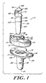
- the invention provides a construction for a knee joint prosthesis system 10 which allows rotation and translation of the tibial component while providing for enhanced posterior stability.
- the design of the prosthesis system of the invention combines enhanced longevity with improved kinematics.
- a tibial component 11 of the joint prosthesis system 10 includes a first component in the form of a tibial tray 14, a second component in the form of a tibial bearing insert 12 and a third component in the form of a separate stabilizing post 22.
- the mounting of the tibial bearing insert 12 to the tibial tray 14 is such that the tibial bearing insert 12 is able to rotate and translate with respect to a proximal or superior surface 32 of the tibial tray 14.
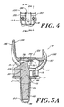
- the system 10 further includes a fourth component in the form of a femoral component 100 which is illustrated in Figures 3-10.
- the tibial bearing insert 12 has an anterior side 13, a posterior side 15, a superior articulation surface 16 and an inferior mating surface 18.
- the superior surface 16 may have one or more condylar elements that are adapted to articulate with complementary condyle(s) of a femoral component as shown in Figures 3-10.
- the condylar elements include lateral and medial condyles 24, 26.
- the tibial bearing insert 12 further has an opening 50 extending therethrough from the superior articulation surface 16 to the inferior mating surface 18.
- the opening 50 may be of any suitable shape which allows for translation and rotation of the tibial bearing insert 12. In one embodiment, discussed below with respect to Figure 11, the opening 50 is elongated in the anterior-posterior direction.
- At least one mating shoulder 28 is formed within opening 50.
- the mating shoulder 28 extends in an arc about the inner circumference of the opening 50.
- the shoulder 28 may be in the form of a continuous arc, or it may be formed in two or more arcs.
- the shoulder 28 includes a proximally facing surface 29.
- the surface 29 may form virtually any angle between 45° and 90° with the inner walls 30 of opening 50. Preferably, however, the surface 29 extends from inner wall 30 at an angle of 90°.
- the inner walls 30 of the opening 50 define a first opening area proximal of the proximally facing surface 29 and a second smaller opening area distal of the surface 29.
- the first opening has a dimension (w) in the medial-lateral direction in the range of about 0.5 to 0.8 inches and preferably 0.65 inches, and a dimension (l) in the anterior-posterior direction in the range of about 0.8 to 1.0 inches and preferably 0.925 inches.
- the second smaller opening has a dimension (w') in the medial-lateral direction in the range of about 0.5 to 0.7 inches and preferably 0.6 inches, and a dimension (l') in the anterior posterior direction in the range of about 0.7 to 0.9 inches and preferably 0.8 inches.
- the shoulder 28 cooperates to seat a complementary distal facing shoulder 78 formed on stabilizing post 22.
- the engagement of shoulders 28 and 78 ensure the proper positioning of post 22 within the tibial tray 14 and the tibial bearing insert 12.
- the tibial tray 14 includes an anterior side 17, a posterior side 19, a superior mating surface 32 and an inferior bone contacting surface 34.
- the bone contacting surface 34 has a first portion 36 that represents an area of the inferior bone contacting surface 34 that mounts upon the proximal surface of a resected tibia (not shown).
- a second portion 38 of the bone contacting surface 34 extends from the first portion 36 and is adapted to extend into a cavity (not shown) formed within a patient's tibia.
- the second portion 38 is an elongate tibial stem 39 that extends from the first portion 36.
- the tibial stem 39 has outer side and distal walls 40, 41.
- the outer side walls 40 of the tibial stem 39 may be smooth, or they may have irregular surface features (not shown) to enhance bone fixation.
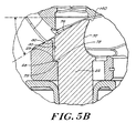
- the superior surface 32 of the tibial tray 14 includes an aperture 72 (which may be of any suitable shape, e.g., substantially circular) that communicates with a mating cavity 44.
- the mating cavity 44 is a blind cavity, defined by interior side walls 45 that extend into the tibial stem.
- the mating cavity 44 terminates in an interior distal wall 46 that may be substantially cone-shaped, or formed in another shape that is suitable for receiving the stabilizing post 22.
- the dimensions of the cavity 44 and the stabilizing post 22 may vary.
- the cavity 44 has a diameter that tapers from proximal 51 to distal 53 ends thereof at an angle in the range of about 0° to 10°.
- the diameter at the proximal end 51 is in the range of about 10 to 20 mm and the diameter at the distal end 53 is in the range of about 5 to 20 mm.
- the cavity 44 preferably has a depth in the range of about 25 to 60 mm and is sized to accept the stabilizing post 22.
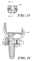
- the stabilizing post 22 includes a proximal end 92 and a distal end 94.
- the proximal end 92 of the stabilizing post 22 includes an enlarged head portion 60.
- the head portion 60 includes an anterior surface 68, a posterior engagement surface 70, and a superior engagement surface 76.
- the distal portion of head 60 includes mating shoulder 78.
- the stem portion 61 of stabilizing post 22 extends distally from the head portion 60.
- the stem portion 61 includes a proximal stem section 62 and a distal stem section 64.
- proximal stem section 62 has a substantially uniform diameter in the range of about 10 to 20 mm.
- the distal stem section 64 has a diameter that tapers distally, ranging from about 10 to 20 mm adjacent the interface 65 between proximal and distal stem sections to about 5 to 20 mm at the distal end 94 of the stabilizing post 22.
- the distal stem section 64 tapers from the interface 65 to the distal end 94 at an angle in the range of about 0° to 10°.
- the dimensions of the stem portion 61 of stabilizing post 22 are such that when engaged within cavity 44 of the tibial tray 14, the stabilizing post 22 cannot be dislodged and is axially stable.
- the overall length of the stabilizing post 22, including head portion 60, is in the range of about 40 to 80 mm.
- the length of the stem portion 61 of post 22, from the mating shoulder 78 to distal end 94, is generally in the range of about 20 to 60 mm.
- the inferior mating shoulder 78 of the stabilizing post 22 includes a distal facing surface 79 and a vertical surface wall 80.
- the mating shoulder 78 is formed due to the dimensions of the post 22 in which the proximal stem section 62 has a diameter such that it is undercut with respect to the superior vertical wall 80 of the head portion.
- the distal facing surface 79 of shoulder 78 may be angled with respect to wall 80 at virtually any angle between 45° and 90°.
- the angle of surface 80 should be complementary with proximally facing surface 29 within opening 50 of tibial bearing insert 12.
- the dimensions by which surface 79 overhang proximal stem section 62 should be sufficient to ensure and maintain engagement with the proximally facing surface 29 within opening 50 of the tibial bearing insert 12.
- this dimension is about 0.5 to 4.0 mm.
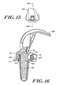
- the tibial bearing insert 12, the tibial tray 14, and the stabilizing post 22 are adapted to fit together to form a tibial component of a knee joint prosthesis.
- the stem portion 61 of the stabilizing post 22 is inserted within the opening 50 of the tibial bearing insert 12 such that extends into the mating cavity 44 of the tibial tray 14.
- the tapered distal stem section 64 of the stabilizing post 22 resides in the cavity 44 of the tibial tray 14 and the proximal stem section 62 is encompassed within the opening 50 of the tibial bearing insert 12.
- the engagement of the tibial bearing insert 12, the tibial tray 14 and the stabilizing post 22 is such that the tibial bearing insert 12 remains independent of the tibial tray 14 and the stabilizing post 22 so that it is able to rotate with respect to these components.
- the opening 50 of the tibial bearing insert 12 is elongated in the anterior-posterior direction.
- the dimensions of this opening can vary depending upon the performance and characteristics desired for a given prosthesis.
- the opening 50 has an anterior-posterior dimension, measured from anterior end 226 to posterior end 228, of about 2 to 4 mm. These dimensions generally provide about 2 to 6 mm of clearance between a centrally positioned post 22 and anterior and posterior end walls 226, 228.
- the tibial bearing insert 12 is permitted to move about 2 to 6 mm from a centrally disposed position to its anterior and posterior extremes, with the movement being substantially in the posterior direction.
- some clearance is provided between post 22 and the lateral and medial 222, 224 side walls of opening 50.
- Such a construction permits a small degree of medial-lateral translation of the tibial bearing insert 12 relative to the tibial tray 14.
- the amount of clearance between stabilizing post 22 and medial and lateral side walls 222, 224 is about 0.25 mm.
- the tibial bearing insert 12 is permitted to translate up to about 0.25 mm in the medial and lateral directions relative to the tibial tray 14.
- the proximal end 92 of the stabilizing post 22 protrudes above the superior articulation surface 16 of the tibial bearing insert 12 when the tibial component of the prosthesis system is assembled.
- the stabilizing post 22 may also rotate with respect to the tibial tray 14. This configuration permits the stabilizing post 22 to engage the femoral component 100 in the manner described below.
- the femoral component 100 has an anterior side 136 and a posterior side 138, and it includes a first surface 116 which is mountable upon the distal end of a patient's femur and a second articulation surface 118.
- the articulation surface 118 includes adjacent lateral 120 and medial 122 condyles which are joined to one another by an intermediate or intercondylar region 123.
- the lateral and medial condyles 120, 122 of the femoral component 100 abut and are able to articulate with the lateral and medial condyles 24, 26 of tibial bearing insert 12.
- each condyle 120, 122 of femoral component 100 and the condyles 24, 26 of tibial bearing insert 12 are configured such that a relatively large contact area is achieved when the condyles of the femoral component and the condyles of the tibial bearing insert mount upon each other.
- each condyle 120, 122 is generally ellipsoid in shape and is of a curved, convex shape in both the anterior-posterior direction and in the medial-lateral direction.
- the intercondylar region 123 includes a first engaging surface 140 and a second engaging surface 150.
- the first engaging surface 140 is oriented at an angle complementary to that of the superior engaging surface 76 of the stabilizing post 22.
- Surface 140 extends from the anterior side 136 of the femoral component 100 towards the posterior side 138 of the femoral component 100.
- the posterior portion of surface 140 meets the second engaging surface 150 located proximate the posterior side 138 of the femoral component 100.
- the second engaging surface 150 has a curved cam-like shape that is generally complementary to the curved posterior engagement surface 70 of the stabilizing post 22.
- the movement of the second engaging surface 150 of the femoral component 100 relative to the curved posterior engagement surface 70 of the stabilizing post 22 produces a posterior translation of the femoral component 100 resulting from the flexion (rotation) of the femoral component 100.
- the shape of the second engaging surface 150 is dependent on factors such as the femoral anterior-posterior profile, the insert topography and the shape/form of the curved posterior engagement surface 70. While the posterior engagement surface 70 is defined by a curvature having a single radius, the second engaging surface 150 may be constructed with two or more radii.
- the first engaging surface 140 of the femoral component 100 abuts or contacts the superior engaging surface 76 of the stabilizing post 22.
- the tibial bearing insert 12 is at a first, generally centered position relative to the tibial tray 14.
- the tibial bearing insert 12 has moved posteriorly during the transition from 0° flexion to 90° flexion. Consequently, optimal roll back of the femoral component with respect to the tibial component is achieved, thereby placing the tibia of a patient anteriorly during flexion of the knee. Consequently, quadriceps muscle efficiency is improved for the patient as a result of the placement of the femur in this position.
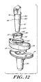
- the prosthesis system includes a tibial bearing insert 12, a tibial tray 14, a sleeve or ring member 20 and a separate stabilizing post 22.
- the ring member 20 is adapted to mate with the tibial bearing insert 12 and act as an articulation surface between the tibial bearing insert 12 and the stabilizing post 22 as the tibial bearing insert 12 translates and rotates.
- the ring member 20 includes a flange portion 21 which may extend partially or entirely around the circumference of ring member 20.
- the flange portion 21 defines an opening 25 which is elongated in the anterior-posterior direction in similar fashion to opening 50 of the tibial bearing insert 12.
- a sidewall portion 23 extends distally from the flange portion 21 and is dimensioned to extend from the proximally facing surface 29 to the inferior mating surface 18 of the tibial bearing insert 12 when the components are assembled.
- the ring member 20 can be made from a variety of materials known to those having ordinary skill in the art. Suitable materials are compatible with stabilizing post 22, possess good wear resistance as well as low friction. Exemplary materials include titanium, titanium alloys, cobalt-chromium alloys, and ultrahigh molecular weight polyethylene.
- the stabilizing post 22 can also be made of a variety of suitable materials, including those from which the ring member 20 may be made.
- the ring member 20 is seated within opening 50 of the tibial bearing insert 12.
- the flange portion 21 of ring member 20 abuts mating shoulder 28 to secure ring member 20 in place with respect to the tibial bearing insert 12.
- the proximal stem section 62 of the stabilizing post 22 is encompassed within a circumferential inner sidewall 27 of ring member 20.
- the distal facing shoulder 78 formed on stabilizing post 22 is seated on the flange portion 21 of ring member 20.
Landscapes
- Health & Medical Sciences (AREA)
- Orthopedic Medicine & Surgery (AREA)
- Physical Education & Sports Medicine (AREA)
- Cardiology (AREA)
- Oral & Maxillofacial Surgery (AREA)
- Transplantation (AREA)
- Engineering & Computer Science (AREA)
- Biomedical Technology (AREA)
- Heart & Thoracic Surgery (AREA)
- Vascular Medicine (AREA)
- Life Sciences & Earth Sciences (AREA)
- Animal Behavior & Ethology (AREA)
- General Health & Medical Sciences (AREA)
- Public Health (AREA)
- Veterinary Medicine (AREA)
- Prostheses (AREA)
Claims (16)
- Gelenkprothesensystem, das umfaßt:dadurch gekennzeichnet, daßeine erste Komponente (64) mit einer superioren Befestigungsoberfläche (32) und einer inferioren Knochenkontaktierungsoberfläche (34), wobei die superiore Befestigungsoberfläche einen Hohlraum aufweist, der durch Wände auf der inneren Seite und durch distale Wände definiert ist;eine zweite Komponente (12) mit einer sich durch diese erstreckenden Öffnung (50), die sich von einer superioren Gelenkverbindungsoberfläche (16) zu einer inferioren Eingreifoberfläche (18) erstreckt, wobei die inferiore Eingreifoberfläche der zweiten Komponente drehbar auf der superioren Befestigungsoberfläche der ersten Komponente befestigt werden kann;und einen davon getrennten Stabilisierungsstift (22) mit proximalem (92) und distalem (94) Ende, wobei der Stift durch die Öffnung der zweiten Komponente einführbar ist und in den Hohlraum der ersten Komponente eingreifen kann, so daß der Stabilisierungsstift, die erste Komponente und die zweite Komponente miteinander gesichert sind,
das proximale Ende (92) des Stabilisierungsstifts von der superioren Gelenkverbindungsoberfläche (16) der zweiten Komponente (12) hervorsteht. - System nach Anspruch 1, wobei das proximale Ende des Stabilisierungsstifts einen Kopfteil mit einer superioren Eingreifoberfläche, einer inferioren eingreifenden Schulter, einer anterioren Oberfläche und einer posterioren Eingreifoberfläche umfaßt.
- System nach Anspruch 2, wobei die inferiore eingreifende Schulter in eine komplementäre eingreifende Schulter eingreift, die in der Öffnung der zweiten Komponente ausgebildet ist.
- System nach Anspruch 2, das weiterhin umfaßt:eine Femoralkomponente mit einer ersten Oberfläche, die an einem distalen Ende eines Oberschenkels eines Patienten befestigt werden kann, und einer zweiten Gelenkverbindungsoberfläche, welche zwei benachbarte semiparallele Kondylen umfaßt, die durch eine Zwischenoberfläche verbunden sind, wobei die Zwischenoberfläche einen ersten Eingreifabschnitt und einen zweiten Eingreifabschnitt umfaßt.
- System nach Anspruch 4, wobei der erste Eingreifabschnitt in die superiore Eingreifoberfläche des Stabilisierungsstiftes eingreift, wenn das System sich in einer Vollstreckung von ungefähr 0° befindet, und wobei der zweite Eingreifabschnitt in die posteriore Eingreifoberfläche des Stabilisierungsstiftes eingreift, wenn das System einen Beugungswinkel von 70° bis 90° aufweist.
- System nach Anspruch 4, wobei jeder Kondylus eine gebogene konvexe Form sowohl in einer anterior-posterioren Richtung als auch in einer medial-lateralen Richtung aufweist.
- System nach Anspruch 1, wobei sich der Hohlraum der ersten Komponente von einem ersten Durchmesser an einem proximalen Ende zu einem zweiten Durchmesser an einem distalen Ende verjüngt.
- System nach Anspruch 7, wobei der Hohlraum einen Durchmesser aufweist, der sich von dem proximalen zu dem distalen Ende des Hohlraums mit einem Winkel von ungefähr 0 bis 10° verjüngt.
- System nach Anspruch 1, wobei der Stabilisierungsstift ein langgestrecktes Element umfaßt, das distal an dessen proximalen Ende angeordnet ist und eine Oberfläche zum Befestigen des Elementes aufweist, die innerhalb des Hohlraums der ersten Komponente befestigbar ist.
- System nach Anspruch 8, wobei das langgestrecktes Element einen proximalen Abschnitt mit einem ersten gleichmäßigen Durchmesser und einen distalen Abschnitt mit einem Durchmesser aufweist, der sich distal verjüngt.
- System nach Anspruch 1, wobei die Öffnung in der zweiten Komponente sich in einer anterior-posterioren Richtung verlängert.
- System nach Anspruch 11, wobei die zweite Komponente in anterior-posteriorer Richtung um bis zu 2 bis 6 mm bezüglich der ersten Komponente beweglich ist.
- System nach Anspruch 11, wobei die zweite Komponente in medial-lateraler Richtung bis zu ungefähr 0,25 mm bezüglich der ersten Komponente beweglich ist.
- System nach Anspruch 11, das ferner ein Ringelement aufweist, das innerhalb der Öffnung der zweiten Komponente befestigt ist.
- System nach Anspruch 14, wobei der Stabilisierungsstift in einen Flanschabschnitt eingreift, der auf dem Ringelement ausgebildet ist.
- System nach Anspruch 1, wobei die erste Komponente eine tibiale Pfanne ist und die zweite Komponente ein tibialer Führungseinsatz ist.
Applications Claiming Priority (2)
| Application Number | Priority Date | Filing Date | Title |
|---|---|---|---|
| US09/112,252 US6080195A (en) | 1998-07-08 | 1998-07-08 | Rotatable and translatable joint prosthesis with posterior stabilization |
| US112252 | 1998-07-08 |
Publications (2)
| Publication Number | Publication Date |
|---|---|
| EP0970667A1 EP0970667A1 (de) | 2000-01-12 |
| EP0970667B1 true EP0970667B1 (de) | 2003-12-03 |
Family
ID=22342905
Family Applications (1)
| Application Number | Title | Priority Date | Filing Date |
|---|---|---|---|
| EP99305390A Expired - Lifetime EP0970667B1 (de) | 1998-07-08 | 1999-07-07 | Drehbare und verschiebbare Gelenkprothese mit hinterer Stabilität |
Country Status (4)
| Country | Link |
|---|---|
| US (1) | US6080195A (de) |
| EP (1) | EP0970667B1 (de) |
| JP (1) | JP4223146B2 (de) |
| DE (1) | DE69913254T2 (de) |
Cited By (12)
| Publication number | Priority date | Publication date | Assignee | Title |
|---|---|---|---|---|
| US7935151B2 (en) | 2001-03-05 | 2011-05-03 | Hudson Surgical Design, Inc. | Femoral prosthetic implant |
| US7967822B2 (en) | 1994-09-02 | 2011-06-28 | Hudson Surgical Design, Inc. | Methods and apparatus for orthopedic implants |
| US8021368B2 (en) | 2004-01-14 | 2011-09-20 | Hudson Surgical Design, Inc. | Methods and apparatus for improved cutting tools for resection |
| US8114083B2 (en) | 2004-01-14 | 2012-02-14 | Hudson Surgical Design, Inc. | Methods and apparatus for improved drilling and milling tools for resection |
| US8287545B2 (en) | 2004-01-14 | 2012-10-16 | Hudson Surgical Design, Inc. | Methods and apparatus for enhanced retention of prosthetic implants |
| US8394147B2 (en) | 2002-12-20 | 2013-03-12 | Smith & Nephew, Inc. | High performance femoral knee prostheses |
| US8603095B2 (en) | 1994-09-02 | 2013-12-10 | Puget Bio Ventures LLC | Apparatuses for femoral and tibial resection |
| US8740906B2 (en) | 2004-01-14 | 2014-06-03 | Hudson Surgical Design, Inc. | Method and apparatus for wireplasty bone resection |
| US8926709B2 (en) | 2010-08-12 | 2015-01-06 | Smith & Nephew, Inc. | Structures for use in orthopaedic implant fixation and methods of installation onto a bone |
| US9056012B2 (en) | 2001-12-21 | 2015-06-16 | Smith & Nephew, Inc. | Hinged joint system |
| US9642711B2 (en) | 2003-10-17 | 2017-05-09 | Smith & Nephew, Inc. | High flexion articular insert |
| US9730799B2 (en) | 2006-06-30 | 2017-08-15 | Smith & Nephew, Inc. | Anatomical motion hinged prosthesis |
Families Citing this family (100)
| Publication number | Priority date | Publication date | Assignee | Title |
|---|---|---|---|---|
| US6428577B1 (en) * | 1998-05-20 | 2002-08-06 | Smith & Nephew, Inc. | Mobile bearing knee prosthesis |
| US6165223A (en) * | 1999-03-01 | 2000-12-26 | Biomet, Inc. | Floating bearing knee joint prosthesis with a fixed tibial post |
| US6413279B1 (en) | 1999-03-01 | 2002-07-02 | Biomet, Inc. | Floating bearing knee joint prosthesis with a fixed tibial post |
| US6972039B2 (en) | 1999-03-01 | 2005-12-06 | Biomet, Inc. | Floating bearing knee joint prosthesis with a fixed tibial post |
| JP3679315B2 (ja) * | 2000-07-19 | 2005-08-03 | 経憲 武井 | 人工膝関節 |
| US6558426B1 (en) | 2000-11-28 | 2003-05-06 | Medidea, Llc | Multiple-cam, posterior-stabilized knee prosthesis |
| US6773461B2 (en) * | 2001-01-29 | 2004-08-10 | Zimmer Technology, Inc. | Constrained prosthetic knee with rotating bearing |
| US6485519B2 (en) | 2001-01-29 | 2002-11-26 | Bristol-Myers Squibb Company | Constrained prosthetic knee with rotating bearing |
| US6719800B2 (en) * | 2001-01-29 | 2004-04-13 | Zimmer Technology, Inc. | Constrained prosthetic knee with rotating bearing |
| US7695521B2 (en) * | 2001-05-01 | 2010-04-13 | Amedica Corporation | Hip prosthesis with monoblock ceramic acetabular cup |
| US20030065397A1 (en) | 2001-08-27 | 2003-04-03 | Hanssen Arlen D. | Prosthetic implant support structure |
| US7892288B2 (en) * | 2001-08-27 | 2011-02-22 | Zimmer Technology, Inc. | Femoral augments for use with knee joint prosthesis |
| US20040162619A1 (en) | 2001-08-27 | 2004-08-19 | Zimmer Technology, Inc. | Tibial augments for use with knee joint prostheses, method of implanting the tibial augment, and associated tools |
| CA2424732C (en) * | 2002-04-10 | 2009-05-26 | Biomedical Engineering Trust I | Prosthetic knee with removable stop pin for limiting anterior sliding movement of bearing |
| US7182786B2 (en) * | 2002-04-25 | 2007-02-27 | Zimmer Technology, Inc. | Modular bone implant, tool, and method |
| US20040002767A1 (en) * | 2002-06-28 | 2004-01-01 | Joseph Wyss | Modular knee joint prosthesis |
| USD684693S1 (en) | 2002-08-22 | 2013-06-18 | Zimmer, Inc. | Prosthetic implant support structure |
| US7008454B2 (en) * | 2003-04-09 | 2006-03-07 | Biomedical Engineering Trust I | Prosthetic knee with removable stop pin for limiting anterior sliding movement of bearing |
| US6986791B1 (en) | 2003-04-15 | 2006-01-17 | Biomet Manufacturing Corp. | Knee prosthesis with moveable post |
| FR2854061B1 (fr) * | 2003-04-24 | 2006-02-03 | Aesculap Sa | Prothese postero-stabilisee a plot femoral anti-basculement |
| FR2854059B1 (fr) * | 2003-04-24 | 2006-01-27 | Aesculap Sa | Plot modulaire pour prothese du genou postero-stabilisee |
| US7534270B2 (en) * | 2003-09-03 | 2009-05-19 | Integra Lifesciences Corporation | Modular total ankle prosthesis apparatuses and methods |
| US7261740B2 (en) | 2003-10-29 | 2007-08-28 | Wright Medical Technology, Inc. | Tibial knee prosthesis |
| US7753960B2 (en) * | 2004-02-26 | 2010-07-13 | Omni Life Science, Inc. | Modular knee prosthesis |
| US7731755B2 (en) * | 2004-06-11 | 2010-06-08 | Depuy Products, Inc. | Posterior stabilized mobile bearing knee |
| US20060142870A1 (en) * | 2004-08-19 | 2006-06-29 | Shawn Robinson | Modular total ankle prosthesis apparatuses, systems and methods, and systems and methods for bone resection and prosthetic implantation |
| US8211181B2 (en) * | 2005-12-14 | 2012-07-03 | New York University | Surface guided knee replacement |
| EP1981439A4 (de) * | 2006-01-20 | 2013-02-06 | Gmbh Synthes | Verfahren zur vorbereitung des fussknöchelersatzes, gelenkprothese und schnittausrichtungsvorrichtung für den einsatz bei der durchführung eines arthroplastikverfahrens |
| JP5101596B2 (ja) | 2006-03-21 | 2012-12-19 | デピュイ・(アイルランド) | モーメント誘発全関節形成人工装具 |
| US9005307B2 (en) | 2006-11-07 | 2015-04-14 | Biomedflex, Llc | Prosthetic ball-and-socket joint |
| CA2668692C (en) * | 2006-11-07 | 2013-06-18 | Biomedflex, Llc | Medical implants |
| US8512413B2 (en) | 2006-11-07 | 2013-08-20 | Biomedflex, Llc | Prosthetic knee joint |
| US8029574B2 (en) * | 2006-11-07 | 2011-10-04 | Biomedflex Llc | Prosthetic knee joint |
| US8070823B2 (en) * | 2006-11-07 | 2011-12-06 | Biomedflex Llc | Prosthetic ball-and-socket joint |
| US20110166671A1 (en) | 2006-11-07 | 2011-07-07 | Kellar Franz W | Prosthetic joint |
| US8308812B2 (en) | 2006-11-07 | 2012-11-13 | Biomedflex, Llc | Prosthetic joint assembly and joint member therefor |
| US8187280B2 (en) | 2007-10-10 | 2012-05-29 | Biomet Manufacturing Corp. | Knee joint prosthesis system and method for implantation |
| US8163028B2 (en) | 2007-01-10 | 2012-04-24 | Biomet Manufacturing Corp. | Knee joint prosthesis system and method for implantation |
| EP2104474B1 (de) | 2007-01-10 | 2012-08-29 | Biomet Manufacturing Corp. | Kniegelenkprothesensystem |
| US8328873B2 (en) | 2007-01-10 | 2012-12-11 | Biomet Manufacturing Corp. | Knee joint prosthesis system and method for implantation |
| US8562616B2 (en) | 2007-10-10 | 2013-10-22 | Biomet Manufacturing, Llc | Knee joint prosthesis system and method for implantation |
| JP5285227B2 (ja) * | 2007-02-26 | 2013-09-11 | 京セラメディカル株式会社 | 生体用補綴体 |
| US8177849B2 (en) * | 2007-05-07 | 2012-05-15 | Zimmer, Inc. | Methods and apparatuses for attaching tissue to orthopaedic implants |
| DK2130516T3 (da) * | 2008-06-03 | 2014-04-07 | Depuy Ireland | Tibiale bøsninger af porøs titan |
| EP2394608A1 (de) | 2008-06-03 | 2011-12-14 | DePuy Products, Inc. | Poröse Titan-Oberschenkelhülsen |
| US8480752B2 (en) * | 2008-06-30 | 2013-07-09 | DePuy Synthes Products, LLC | Tibial bearing having increased axial-rotation |
| US8828086B2 (en) | 2008-06-30 | 2014-09-09 | Depuy (Ireland) | Orthopaedic femoral component having controlled condylar curvature |
| US8206451B2 (en) | 2008-06-30 | 2012-06-26 | Depuy Products, Inc. | Posterior stabilized orthopaedic prosthesis |
| US8187335B2 (en) | 2008-06-30 | 2012-05-29 | Depuy Products, Inc. | Posterior stabilized orthopaedic knee prosthesis having controlled condylar curvature |
| US9168145B2 (en) | 2008-06-30 | 2015-10-27 | Depuy (Ireland) | Posterior stabilized orthopaedic knee prosthesis having controlled condylar curvature |
| US8236061B2 (en) | 2008-06-30 | 2012-08-07 | Depuy Products, Inc. | Orthopaedic knee prosthesis having controlled condylar curvature |
| US8075626B2 (en) * | 2008-06-30 | 2011-12-13 | Depuy Products, Inc. | Orthopaedic knee prosthesis having increased axial-rotation |
| US9119723B2 (en) | 2008-06-30 | 2015-09-01 | Depuy (Ireland) | Posterior stabilized orthopaedic prosthesis assembly |
| US8192498B2 (en) | 2008-06-30 | 2012-06-05 | Depuy Products, Inc. | Posterior cructiate-retaining orthopaedic knee prosthesis having controlled condylar curvature |
| GB0812631D0 (en) * | 2008-07-10 | 2008-08-20 | Imp Innovations Ltd | Modular knee implants |
| US8202323B2 (en) * | 2008-07-16 | 2012-06-19 | Depuy Products, Inc. | Knee prostheses with enhanced kinematics |
| WO2010056962A1 (en) * | 2008-11-14 | 2010-05-20 | Barker Bretell | Transiently mobile tibial engagement |
| US9220600B2 (en) | 2008-12-23 | 2015-12-29 | Aesculap Implant Systems, Llc | Knee prosthesis |
| US20100161067A1 (en) * | 2008-12-23 | 2010-06-24 | Aesculap Ag | Knee prosthesis |
| US8491662B2 (en) | 2008-12-23 | 2013-07-23 | Aesculap Ag | Knee prosthesis |
| US8915965B2 (en) | 2009-05-07 | 2014-12-23 | Depuy (Ireland) | Anterior stabilized knee implant |
| US8152853B2 (en) * | 2009-06-05 | 2012-04-10 | Biomet Manufacturing Corp. | Knee prosthesis with rotatable post |
| DE202009008370U1 (de) * | 2009-06-17 | 2010-10-28 | Lawton Gmbh & Co. Kg | Chirurgisches Instrument |
| US9095453B2 (en) * | 2009-08-11 | 2015-08-04 | Michael D. Ries | Position adjustable trial systems for prosthetic implants |
| US8906105B2 (en) | 2009-08-11 | 2014-12-09 | Michael D. Ries | Systems and methods for mobile bearing prosthetic knee |
| US8496666B2 (en) | 2009-08-11 | 2013-07-30 | Imds Corporation | Instrumentation for mobile bearing prosthetics |
| US8568485B2 (en) * | 2009-08-11 | 2013-10-29 | Imds Corporation | Articulating trials for prosthetic implants |
| US8382848B2 (en) * | 2009-08-11 | 2013-02-26 | Imds Corporation | Position adjustable trial systems for prosthetic implants |
| US8998997B2 (en) | 2009-08-11 | 2015-04-07 | Michael D. Ries | Implantable mobile bearing prosthetics |
| FR2951369B1 (fr) | 2009-10-21 | 2012-06-29 | Laurent Buisson | Prothese totale du genou a plateau mobile |
| DE102010000067A1 (de) * | 2010-01-13 | 2011-07-14 | Aesculap AG, 78532 | Kniegelenkendoprothese |
| WO2011094540A2 (en) | 2010-01-29 | 2011-08-04 | Smith & Nephew, Inc. | Cruciate-retaining knee prosthesis |
| US8308808B2 (en) * | 2010-02-19 | 2012-11-13 | Biomet Manufacturing Corp. | Latent mobile bearing for prosthetic device |
| EP2595571B1 (de) | 2010-07-23 | 2015-09-09 | Michael D. Ries | Systeme für eine knieprothese |
| WO2012018567A1 (en) | 2010-07-24 | 2012-02-09 | Zimmer, Inc. | Asymmetric tibial components for a knee prosthesis |
| US8628580B2 (en) | 2010-07-24 | 2014-01-14 | Zimmer, Inc. | Tibial prosthesis |
| EP2613739B1 (de) | 2010-09-10 | 2017-06-07 | Zimmer, Inc. | Bewegungsermöglichende tibiakomponenten für eine knieprothese |
| ES2443827T3 (es) | 2010-10-05 | 2014-02-20 | Aesculap Ag | Endoprótesis de articulación de rodilla |
| US9675464B2 (en) * | 2010-10-28 | 2017-06-13 | Gerald J. Jerry | Tibial tray system and method of implantation |
| US8603101B2 (en) | 2010-12-17 | 2013-12-10 | Zimmer, Inc. | Provisional tibial prosthesis system |
| CA2836772C (en) | 2011-05-20 | 2020-03-10 | Zimmer, Inc. | Stabilizing prosthesis support structure |
| EP3372201B1 (de) | 2011-11-18 | 2020-05-20 | Zimmer, Inc. | Schienbeinträgerkomponente für eine knieprothese mit verbesserten gelenkeigenschaften |
| ES2585838T3 (es) | 2011-11-21 | 2016-10-10 | Zimmer, Inc. | Placa de base tibial con la colocación asimétrica de estructuras de fijación |
| US10258477B2 (en) * | 2011-12-07 | 2019-04-16 | Smith & Nephew, Inc. | Tibial insert with resistance-actuated post |
| WO2013115849A1 (en) | 2012-01-30 | 2013-08-08 | Zimmer, Inc. | Asymmetric tibial components for a knee prosthesis |
| US9597189B2 (en) * | 2012-04-26 | 2017-03-21 | Consensus Orthopedics, Inc. | Prosthetic tibial component for knee joint prosthesis |
| WO2014143538A1 (en) | 2013-03-14 | 2014-09-18 | Wasielewski Ray C | Knee prosthesis including rotatable spine |
| US9925052B2 (en) | 2013-08-30 | 2018-03-27 | Zimmer, Inc. | Method for optimizing implant designs |
| FR3016284B1 (fr) | 2014-01-14 | 2019-08-16 | Evolutis | Prothese postero stabilisee du genou |
| KR101707592B1 (ko) * | 2015-03-05 | 2017-02-17 | 주식회사 코렌텍 | 인공슬관절용 인서트 유닛 |
| CN108135701B (zh) | 2015-09-21 | 2019-12-24 | 捷迈有限公司 | 包括胫骨承载组件的假体系统 |
| US10179052B2 (en) | 2016-07-28 | 2019-01-15 | Depuy Ireland Unlimited Company | Total knee implant prosthesis assembly and method |
| EP3570787B1 (de) | 2017-01-20 | 2022-05-04 | Biomet Manufacturing, LLC | Modulare vegrösserungskomponente |
| EP4014930B1 (de) | 2017-03-10 | 2025-04-16 | Zimmer, Inc. | Schienbeinprothese mit sicherung der tibialagerkomponente |
| CA3063415C (en) | 2017-05-12 | 2021-10-19 | Zimmer, Inc. | Femoral prostheses with upsizing and downsizing capabilities |
| US10925743B2 (en) * | 2017-09-26 | 2021-02-23 | Stephen J. Incavo | Knee arthroplasty with modular femoral adapters |
| US11426282B2 (en) | 2017-11-16 | 2022-08-30 | Zimmer, Inc. | Implants for adding joint inclination to a knee arthroplasty |
| US10835380B2 (en) | 2018-04-30 | 2020-11-17 | Zimmer, Inc. | Posterior stabilized prosthesis system |
| US12478477B2 (en) | 2021-12-21 | 2025-11-25 | Depuy Ireland Unlimited Company | Modular tibial cone augments and method of surgically using the same |
| US12115084B2 (en) | 2021-12-21 | 2024-10-15 | Depuy Ireland Unlimited Company | Method of installing a knee cone augment in an orthopaedic surgical procedure |
Family Cites Families (15)
| Publication number | Priority date | Publication date | Assignee | Title |
|---|---|---|---|---|
| US4257129A (en) * | 1979-05-21 | 1981-03-24 | Volz Robert G | Prosthetic knee joint tibial implant |
| DE3529894A1 (de) * | 1985-08-21 | 1987-03-05 | Orthoplant Endoprothetik | Kniegelenk-endoprothese |
| US5147405A (en) * | 1990-02-07 | 1992-09-15 | Boehringer Mannheim Corporation | Knee prosthesis |
| AU9089891A (en) * | 1990-11-14 | 1992-06-11 | Arch Development Corporation | Improved floating bearing prosthetic knee |
| DE59209628D1 (de) * | 1992-01-14 | 1999-03-11 | Sulzer Orthopaedie Ag | Meniskusplattform zu künstlichem Kniegelenk |
| NZ243181A (en) * | 1992-04-23 | 1994-10-26 | Michael John Pappas | Prosthetic joint with guide means to limit articulation of a first element and bearing means to two degrees of freedom |
| US5824102A (en) * | 1992-06-19 | 1998-10-20 | Buscayret; Christian | Total knee prosthesis |
| US5658342A (en) * | 1992-11-16 | 1997-08-19 | Arch Development | Stabilized prosthetic knee |
| GB9415180D0 (en) * | 1994-07-28 | 1994-09-21 | Walker Peter S | Stabilised mobile bearing knee |
| US5824096A (en) * | 1994-12-12 | 1998-10-20 | Biomedical Engineering Trust I | Hinged knee prosthesis with condylar bearing |
| US5639279A (en) * | 1995-02-09 | 1997-06-17 | Intermedics Orthopedics, Inc. | Posteriorly-stabilized prosthetic knee |
| US5683468A (en) * | 1995-03-13 | 1997-11-04 | Pappas; Michael J. | Mobile bearing total joint replacement |
| GB9609609D0 (en) * | 1996-05-08 | 1996-07-10 | Midland International Orthopae | Knee prosthesis |
| GB9611060D0 (en) * | 1996-05-28 | 1996-07-31 | Howmedica | Tibial element for a replacment knee prosthesis |
| CA2217844C (en) * | 1996-10-09 | 2006-05-16 | Michael J. Pappas | Prosthetic knee joint with enhanced posterior stabilization |
-
1998
- 1998-07-08 US US09/112,252 patent/US6080195A/en not_active Expired - Lifetime
-
1999
- 1999-07-07 EP EP99305390A patent/EP0970667B1/de not_active Expired - Lifetime
- 1999-07-07 JP JP19354099A patent/JP4223146B2/ja not_active Expired - Fee Related
- 1999-07-07 DE DE69913254T patent/DE69913254T2/de not_active Expired - Lifetime
Cited By (30)
| Publication number | Priority date | Publication date | Assignee | Title |
|---|---|---|---|---|
| US7967822B2 (en) | 1994-09-02 | 2011-06-28 | Hudson Surgical Design, Inc. | Methods and apparatus for orthopedic implants |
| US9066804B2 (en) | 1994-09-02 | 2015-06-30 | Puget Bioventures Llc | Method and apparatus for femoral and tibial resection |
| US8603095B2 (en) | 1994-09-02 | 2013-12-10 | Puget Bio Ventures LLC | Apparatuses for femoral and tibial resection |
| US8062377B2 (en) | 2001-03-05 | 2011-11-22 | Hudson Surgical Design, Inc. | Methods and apparatus for knee arthroplasty |
| US8088167B2 (en) | 2001-03-05 | 2012-01-03 | Hudson Surgical Design, Inc. | Femoral prosthetic implant |
| US9192391B2 (en) | 2001-03-05 | 2015-11-24 | Puget Bioventures Llc | Method for minimally invasive total knee arthroplasty |
| US7935151B2 (en) | 2001-03-05 | 2011-05-03 | Hudson Surgical Design, Inc. | Femoral prosthetic implant |
| US8430932B2 (en) | 2001-03-05 | 2013-04-30 | Puget Bio Ventures LLC | Femoral prosthetic implant |
| US9056012B2 (en) | 2001-12-21 | 2015-06-16 | Smith & Nephew, Inc. | Hinged joint system |
| US9381087B2 (en) | 2001-12-21 | 2016-07-05 | Smith & Nephew, Inc. | Hinged joint system |
| US8394148B2 (en) | 2002-12-20 | 2013-03-12 | Smith & Nephew, Inc. | Tibial component of high performance knee prosthesis |
| US8398716B2 (en) | 2002-12-20 | 2013-03-19 | Smith & Nephew, Inc. | High performance knee prostheses with posterior cam |
| US8403992B2 (en) | 2002-12-20 | 2013-03-26 | Smith & Nephew, Inc. | High performance knee prostheses |
| US8425617B2 (en) | 2002-12-20 | 2013-04-23 | Smith & Nephew, Inc. | Knee prostheses with convex slope on portion of tibial articular surface |
| US8394147B2 (en) | 2002-12-20 | 2013-03-12 | Smith & Nephew, Inc. | High performance femoral knee prostheses |
| US8449618B2 (en) | 2002-12-20 | 2013-05-28 | Smith & Nephew, Inc. | High performance knee prostheses |
| US9320605B2 (en) | 2002-12-20 | 2016-04-26 | Smith & Nephew, Inc. | High performance knee prostheses |
| US8603178B2 (en) | 2002-12-20 | 2013-12-10 | Smith & Nephew, Inc. | Knee prostheses with convex portion on tibial lateral articular surface |
| US8647389B2 (en) | 2002-12-20 | 2014-02-11 | Smith & Nephew, Inc. | High performance knee prostheses |
| US8652210B2 (en) | 2002-12-20 | 2014-02-18 | Smith & Nephew, Inc. | Femoral prostheses with lateral buttress for patella |
| US9402729B2 (en) | 2002-12-20 | 2016-08-02 | Smith & Nephew, Inc. | High performance knee prostheses |
| US9642711B2 (en) | 2003-10-17 | 2017-05-09 | Smith & Nephew, Inc. | High flexion articular insert |
| US8298238B2 (en) | 2004-01-14 | 2012-10-30 | Hudson Surgical Design, Inc. | Methods and apparatus for pivotable guide surfaces for arthroplasty |
| US8740906B2 (en) | 2004-01-14 | 2014-06-03 | Hudson Surgical Design, Inc. | Method and apparatus for wireplasty bone resection |
| US8287545B2 (en) | 2004-01-14 | 2012-10-16 | Hudson Surgical Design, Inc. | Methods and apparatus for enhanced retention of prosthetic implants |
| US8114083B2 (en) | 2004-01-14 | 2012-02-14 | Hudson Surgical Design, Inc. | Methods and apparatus for improved drilling and milling tools for resection |
| US8021368B2 (en) | 2004-01-14 | 2011-09-20 | Hudson Surgical Design, Inc. | Methods and apparatus for improved cutting tools for resection |
| US8353914B2 (en) | 2004-02-02 | 2013-01-15 | Hudson Surgical Design, Inc. | Methods and apparatus for improved profile based resection |
| US9730799B2 (en) | 2006-06-30 | 2017-08-15 | Smith & Nephew, Inc. | Anatomical motion hinged prosthesis |
| US8926709B2 (en) | 2010-08-12 | 2015-01-06 | Smith & Nephew, Inc. | Structures for use in orthopaedic implant fixation and methods of installation onto a bone |
Also Published As
| Publication number | Publication date |
|---|---|
| EP0970667A1 (de) | 2000-01-12 |
| US6080195A (en) | 2000-06-27 |
| JP2000051252A (ja) | 2000-02-22 |
| JP4223146B2 (ja) | 2009-02-12 |
| DE69913254D1 (de) | 2004-01-15 |
| DE69913254T2 (de) | 2004-12-02 |
Similar Documents
| Publication | Publication Date | Title |
|---|---|---|
| EP0970667B1 (de) | Drehbare und verschiebbare Gelenkprothese mit hinterer Stabilität | |
| EP0904750B1 (de) | Drehbare Gelenkprothese mit axialer Fixierung | |
| EP1333785B1 (de) | Schwimmend stützende kniegelenksprothese mit fixiertem tibialpfosten | |
| EP0904748B1 (de) | Gelenkprothesensystem mit einer in Längsrichtung verschlossenen drehbaren Komponente | |
| EP0904749B1 (de) | Gelenkprothese mit kontrollierter Drehbewegung | |
| EP1025818B1 (de) | Modulares Gelenkprothesensystem | |
| US20250032264A1 (en) | Total knee implant prosthesis assembly and method | |
| CA2187033C (en) | Stabilized prosthetic knee | |
| EP1591083B1 (de) | Knieprothese | |
| EP1292243B1 (de) | Kniegelenkprothese mit beweglichem lager und fixiertem tibialen stamm | |
| CA2542619C (en) | High flexion articular insert | |
| EP1023881B1 (de) | Modularer tibialer Einsatz für ein prosthetisches System | |
| EP0510178B1 (de) | Verbesserte knieprothese mit beweglichem lager | |
| AU2011221425A1 (en) | High flexion articular insert |
Legal Events
| Date | Code | Title | Description |
|---|---|---|---|
| PUAI | Public reference made under article 153(3) epc to a published international application that has entered the european phase |
Free format text: ORIGINAL CODE: 0009012 |
|
| AK | Designated contracting states |
Kind code of ref document: A1 Designated state(s): DE FR GB IE IT |
|
| AX | Request for extension of the european patent |
Free format text: AL;LT;LV;MK;RO;SI |
|
| 17P | Request for examination filed |
Effective date: 20000616 |
|
| AKX | Designation fees paid |
Free format text: DE FR GB IE IT |
|
| 17Q | First examination report despatched |
Effective date: 20020718 |
|
| RAP1 | Party data changed (applicant data changed or rights of an application transferred) |
Owner name: DEPUY PRODUCTS, INC. |
|
| RAP1 | Party data changed (applicant data changed or rights of an application transferred) |
Owner name: DEPUY PRODUCTS, INC. |
|
| GRAH | Despatch of communication of intention to grant a patent |
Free format text: ORIGINAL CODE: EPIDOS IGRA |
|
| GRAS | Grant fee paid |
Free format text: ORIGINAL CODE: EPIDOSNIGR3 |
|
| GRAA | (expected) grant |
Free format text: ORIGINAL CODE: 0009210 |
|
| AK | Designated contracting states |
Kind code of ref document: B1 Designated state(s): DE FR GB IE IT |
|
| REG | Reference to a national code |
Ref country code: GB Ref legal event code: FG4D |
|
| REG | Reference to a national code |
Ref country code: IE Ref legal event code: FG4D |
|
| REF | Corresponds to: |
Ref document number: 69913254 Country of ref document: DE Date of ref document: 20040115 Kind code of ref document: P |
|
| ET | Fr: translation filed | ||
| PLBE | No opposition filed within time limit |
Free format text: ORIGINAL CODE: 0009261 |
|
| STAA | Information on the status of an ep patent application or granted ep patent |
Free format text: STATUS: NO OPPOSITION FILED WITHIN TIME LIMIT |
|
| 26N | No opposition filed |
Effective date: 20040906 |
|
| PGFP | Annual fee paid to national office [announced via postgrant information from national office to epo] |
Ref country code: DE Payment date: 20140702 Year of fee payment: 16 Ref country code: IE Payment date: 20140710 Year of fee payment: 16 |
|
| PGFP | Annual fee paid to national office [announced via postgrant information from national office to epo] |
Ref country code: GB Payment date: 20140702 Year of fee payment: 16 Ref country code: FR Payment date: 20140708 Year of fee payment: 16 |
|
| PGFP | Annual fee paid to national office [announced via postgrant information from national office to epo] |
Ref country code: IT Payment date: 20140717 Year of fee payment: 16 |
|
| REG | Reference to a national code |
Ref country code: DE Ref legal event code: R119 Ref document number: 69913254 Country of ref document: DE |
|
| GBPC | Gb: european patent ceased through non-payment of renewal fee |
Effective date: 20150707 |
|
| REG | Reference to a national code |
Ref country code: IE Ref legal event code: MM4A |
|
| PG25 | Lapsed in a contracting state [announced via postgrant information from national office to epo] |
Ref country code: IT Free format text: LAPSE BECAUSE OF NON-PAYMENT OF DUE FEES Effective date: 20150707 Ref country code: DE Free format text: LAPSE BECAUSE OF NON-PAYMENT OF DUE FEES Effective date: 20160202 Ref country code: GB Free format text: LAPSE BECAUSE OF NON-PAYMENT OF DUE FEES Effective date: 20150707 |
|
| REG | Reference to a national code |
Ref country code: FR Ref legal event code: ST Effective date: 20160331 |
|
| PG25 | Lapsed in a contracting state [announced via postgrant information from national office to epo] |
Ref country code: FR Free format text: LAPSE BECAUSE OF NON-PAYMENT OF DUE FEES Effective date: 20150731 |
|
| PG25 | Lapsed in a contracting state [announced via postgrant information from national office to epo] |
Ref country code: IE Free format text: LAPSE BECAUSE OF NON-PAYMENT OF DUE FEES Effective date: 20150707 |