EP0904748B1 - Gelenkprothesensystem mit einer in Längsrichtung verschlossenen drehbaren Komponente - Google Patents
Gelenkprothesensystem mit einer in Längsrichtung verschlossenen drehbaren Komponente Download PDFInfo
- Publication number
- EP0904748B1 EP0904748B1 EP98307768A EP98307768A EP0904748B1 EP 0904748 B1 EP0904748 B1 EP 0904748B1 EP 98307768 A EP98307768 A EP 98307768A EP 98307768 A EP98307768 A EP 98307768A EP 0904748 B1 EP0904748 B1 EP 0904748B1
- Authority
- EP
- European Patent Office
- Prior art keywords
- cavity
- stem
- component
- mating
- tibial
- Prior art date
- Legal status (The legal status is an assumption and is not a legal conclusion. Google has not performed a legal analysis and makes no representation as to the accuracy of the status listed.)
- Expired - Lifetime
Links
- 230000013011 mating Effects 0.000 claims description 61
- 230000002787 reinforcement Effects 0.000 claims description 6
- 230000000295 complement effect Effects 0.000 claims description 5
- 238000003780 insertion Methods 0.000 claims 1
- 230000037431 insertion Effects 0.000 claims 1
- 210000000629 knee joint Anatomy 0.000 description 13
- 210000003127 knee Anatomy 0.000 description 8
- 210000000988 bone and bone Anatomy 0.000 description 5
- 210000002303 tibia Anatomy 0.000 description 4
- 238000000926 separation method Methods 0.000 description 3
- 239000000463 material Substances 0.000 description 2
- 229910052751 metal Inorganic materials 0.000 description 2
- 239000002184 metal Substances 0.000 description 2
- 229910001092 metal group alloy Inorganic materials 0.000 description 2
- 238000012986 modification Methods 0.000 description 2
- 230000004048 modification Effects 0.000 description 2
- 238000001356 surgical procedure Methods 0.000 description 2
- 206010023204 Joint dislocation Diseases 0.000 description 1
- 229920010741 Ultra High Molecular Weight Polyethylene (UHMWPE) Polymers 0.000 description 1
- 239000004699 Ultra-high molecular weight polyethylene Substances 0.000 description 1
- 239000000919 ceramic Substances 0.000 description 1
- 238000006073 displacement reaction Methods 0.000 description 1
- 230000001788 irregular Effects 0.000 description 1
- 150000002739 metals Chemical class 0.000 description 1
- 210000004417 patella Anatomy 0.000 description 1
- 239000004033 plastic Substances 0.000 description 1
- 229920003023 plastic Polymers 0.000 description 1
- 229920000785 ultra high molecular weight polyethylene Polymers 0.000 description 1
Images

Classifications
-
- A—HUMAN NECESSITIES
- A61—MEDICAL OR VETERINARY SCIENCE; HYGIENE
- A61F—FILTERS IMPLANTABLE INTO BLOOD VESSELS; PROSTHESES; DEVICES PROVIDING PATENCY TO, OR PREVENTING COLLAPSING OF, TUBULAR STRUCTURES OF THE BODY, e.g. STENTS; ORTHOPAEDIC, NURSING OR CONTRACEPTIVE DEVICES; FOMENTATION; TREATMENT OR PROTECTION OF EYES OR EARS; BANDAGES, DRESSINGS OR ABSORBENT PADS; FIRST-AID KITS
- A61F2/00—Filters implantable into blood vessels; Prostheses, i.e. artificial substitutes or replacements for parts of the body; Appliances for connecting them with the body; Devices providing patency to, or preventing collapsing of, tubular structures of the body, e.g. stents
- A61F2/02—Prostheses implantable into the body
- A61F2/30—Joints
- A61F2/38—Joints for elbows or knees
- A61F2/3868—Joints for elbows or knees with sliding tibial bearing
-
- A—HUMAN NECESSITIES
- A61—MEDICAL OR VETERINARY SCIENCE; HYGIENE
- A61F—FILTERS IMPLANTABLE INTO BLOOD VESSELS; PROSTHESES; DEVICES PROVIDING PATENCY TO, OR PREVENTING COLLAPSING OF, TUBULAR STRUCTURES OF THE BODY, e.g. STENTS; ORTHOPAEDIC, NURSING OR CONTRACEPTIVE DEVICES; FOMENTATION; TREATMENT OR PROTECTION OF EYES OR EARS; BANDAGES, DRESSINGS OR ABSORBENT PADS; FIRST-AID KITS
- A61F2/00—Filters implantable into blood vessels; Prostheses, i.e. artificial substitutes or replacements for parts of the body; Appliances for connecting them with the body; Devices providing patency to, or preventing collapsing of, tubular structures of the body, e.g. stents
- A61F2/02—Prostheses implantable into the body
- A61F2/30—Joints
- A61F2002/30001—Additional features of subject-matter classified in A61F2/28, A61F2/30 and subgroups thereof
- A61F2002/30108—Shapes
- A61F2002/30199—Three-dimensional shapes
- A61F2002/30224—Three-dimensional shapes cylindrical
- A61F2002/30233—Stepped cylinders, i.e. having discrete diameter changes
-
- A—HUMAN NECESSITIES
- A61—MEDICAL OR VETERINARY SCIENCE; HYGIENE
- A61F—FILTERS IMPLANTABLE INTO BLOOD VESSELS; PROSTHESES; DEVICES PROVIDING PATENCY TO, OR PREVENTING COLLAPSING OF, TUBULAR STRUCTURES OF THE BODY, e.g. STENTS; ORTHOPAEDIC, NURSING OR CONTRACEPTIVE DEVICES; FOMENTATION; TREATMENT OR PROTECTION OF EYES OR EARS; BANDAGES, DRESSINGS OR ABSORBENT PADS; FIRST-AID KITS
- A61F2/00—Filters implantable into blood vessels; Prostheses, i.e. artificial substitutes or replacements for parts of the body; Appliances for connecting them with the body; Devices providing patency to, or preventing collapsing of, tubular structures of the body, e.g. stents
- A61F2/02—Prostheses implantable into the body
- A61F2/30—Joints
- A61F2002/30001—Additional features of subject-matter classified in A61F2/28, A61F2/30 and subgroups thereof
- A61F2002/30316—The prosthesis having different structural features at different locations within the same prosthesis; Connections between prosthetic parts; Special structural features of bone or joint prostheses not otherwise provided for
- A61F2002/30329—Connections or couplings between prosthetic parts, e.g. between modular parts; Connecting elements
- A61F2002/30426—Bayonet coupling
-
- A—HUMAN NECESSITIES
- A61—MEDICAL OR VETERINARY SCIENCE; HYGIENE
- A61F—FILTERS IMPLANTABLE INTO BLOOD VESSELS; PROSTHESES; DEVICES PROVIDING PATENCY TO, OR PREVENTING COLLAPSING OF, TUBULAR STRUCTURES OF THE BODY, e.g. STENTS; ORTHOPAEDIC, NURSING OR CONTRACEPTIVE DEVICES; FOMENTATION; TREATMENT OR PROTECTION OF EYES OR EARS; BANDAGES, DRESSINGS OR ABSORBENT PADS; FIRST-AID KITS
- A61F2/00—Filters implantable into blood vessels; Prostheses, i.e. artificial substitutes or replacements for parts of the body; Appliances for connecting them with the body; Devices providing patency to, or preventing collapsing of, tubular structures of the body, e.g. stents
- A61F2/02—Prostheses implantable into the body
- A61F2/30—Joints
- A61F2002/30001—Additional features of subject-matter classified in A61F2/28, A61F2/30 and subgroups thereof
- A61F2002/30316—The prosthesis having different structural features at different locations within the same prosthesis; Connections between prosthetic parts; Special structural features of bone or joint prostheses not otherwise provided for
- A61F2002/30535—Special structural features of bone or joint prostheses not otherwise provided for
- A61F2002/30604—Special structural features of bone or joint prostheses not otherwise provided for modular
-
- A—HUMAN NECESSITIES
- A61—MEDICAL OR VETERINARY SCIENCE; HYGIENE
- A61F—FILTERS IMPLANTABLE INTO BLOOD VESSELS; PROSTHESES; DEVICES PROVIDING PATENCY TO, OR PREVENTING COLLAPSING OF, TUBULAR STRUCTURES OF THE BODY, e.g. STENTS; ORTHOPAEDIC, NURSING OR CONTRACEPTIVE DEVICES; FOMENTATION; TREATMENT OR PROTECTION OF EYES OR EARS; BANDAGES, DRESSINGS OR ABSORBENT PADS; FIRST-AID KITS
- A61F2/00—Filters implantable into blood vessels; Prostheses, i.e. artificial substitutes or replacements for parts of the body; Appliances for connecting them with the body; Devices providing patency to, or preventing collapsing of, tubular structures of the body, e.g. stents
- A61F2/02—Prostheses implantable into the body
- A61F2/30—Joints
- A61F2/30767—Special external or bone-contacting surface, e.g. coating for improving bone ingrowth
- A61F2/30771—Special external or bone-contacting surface, e.g. coating for improving bone ingrowth applied in original prostheses, e.g. holes or grooves
- A61F2002/30878—Special external or bone-contacting surface, e.g. coating for improving bone ingrowth applied in original prostheses, e.g. holes or grooves with non-sharp protrusions, for instance contacting the bone for anchoring, e.g. keels, pegs, pins, posts, shanks, stems, struts
- A61F2002/30884—Fins or wings, e.g. longitudinal wings for preventing rotation within the bone cavity
-
- A—HUMAN NECESSITIES
- A61—MEDICAL OR VETERINARY SCIENCE; HYGIENE
- A61F—FILTERS IMPLANTABLE INTO BLOOD VESSELS; PROSTHESES; DEVICES PROVIDING PATENCY TO, OR PREVENTING COLLAPSING OF, TUBULAR STRUCTURES OF THE BODY, e.g. STENTS; ORTHOPAEDIC, NURSING OR CONTRACEPTIVE DEVICES; FOMENTATION; TREATMENT OR PROTECTION OF EYES OR EARS; BANDAGES, DRESSINGS OR ABSORBENT PADS; FIRST-AID KITS
- A61F2220/00—Fixations or connections for prostheses classified in groups A61F2/00 - A61F2/26 or A61F2/82 or A61F9/00 or A61F11/00 or subgroups thereof
- A61F2220/0025—Connections or couplings between prosthetic parts, e.g. between modular parts; Connecting elements
-
- A—HUMAN NECESSITIES
- A61—MEDICAL OR VETERINARY SCIENCE; HYGIENE
- A61F—FILTERS IMPLANTABLE INTO BLOOD VESSELS; PROSTHESES; DEVICES PROVIDING PATENCY TO, OR PREVENTING COLLAPSING OF, TUBULAR STRUCTURES OF THE BODY, e.g. STENTS; ORTHOPAEDIC, NURSING OR CONTRACEPTIVE DEVICES; FOMENTATION; TREATMENT OR PROTECTION OF EYES OR EARS; BANDAGES, DRESSINGS OR ABSORBENT PADS; FIRST-AID KITS
- A61F2230/00—Geometry of prostheses classified in groups A61F2/00 - A61F2/26 or A61F2/82 or A61F9/00 or A61F11/00 or subgroups thereof
- A61F2230/0063—Three-dimensional shapes
- A61F2230/0069—Three-dimensional shapes cylindrical
-
- A—HUMAN NECESSITIES
- A61—MEDICAL OR VETERINARY SCIENCE; HYGIENE
- A61F—FILTERS IMPLANTABLE INTO BLOOD VESSELS; PROSTHESES; DEVICES PROVIDING PATENCY TO, OR PREVENTING COLLAPSING OF, TUBULAR STRUCTURES OF THE BODY, e.g. STENTS; ORTHOPAEDIC, NURSING OR CONTRACEPTIVE DEVICES; FOMENTATION; TREATMENT OR PROTECTION OF EYES OR EARS; BANDAGES, DRESSINGS OR ABSORBENT PADS; FIRST-AID KITS
- A61F2310/00—Prostheses classified in A61F2/28 or A61F2/30 - A61F2/44 being constructed from or coated with a particular material
- A61F2310/00005—The prosthesis being constructed from a particular material
- A61F2310/00011—Metals or alloys
Definitions
- the invention relates to joint prostheses and more particularly to tibial components of knee joint prostheses that feature a tibial bearing insert that is rotatable with respect to a tibial tray upon which it is mounted.
- Knee arthoplasty is a well known surgical procedure by which a diseased and/or damaged natural knee joint is replaced with a prosthetic knee joint.
- Typical knee protheses include a femoral component, a patella component, a tibial tray or plateau, and a tibial bearing insert.
- the femoral component generally includes a pair of laterally spaced apart condylar portions, the distal surfaces of which articulate with complementary condylar elements formed in a tibial bearing insert.
- the tibial tray is mounted within the tibia of a patient.
- the tibial bearing insert which is usually made of ultra high molecular weight polyethylene (UHMWPE) is mounted upon the superior surface of the tibial tray.
- UHMWPE ultra high molecular weight polyethylene
- Load and stress are placed upon the knee prosthesis, and particularly on the tibial bearing insert, during normal daily use. These forces may lead to the displacement or dislocation of the insert from the tibial tray.
- some tibial components of knee prostheses have been designed to allow rotation of the tibial bearing insert relative to the proximal or superior surface of the tibial tray, about the longitudinal axis of the prosthesis. Such rotation, when controlled, can increase the contact area between the femoral condyles and the tibial bearing insert throughout the range of knee motion, thus reducing stress on the tibial bearing insert.
- Some knee prosthesis tibial components accommodate insert rotation without providing axial securement of the tibial bearing insert within the tibial tray. That is, some tibial bearing inserts that are able to rotate with respect to a tibial tray are not fully secured within the tibial tray. Certain forces to which the knee is subjected, particularly forces with axially directed components, may cause the tibial bearing insert to separate from the tibial tray.
- the document FR 2 601 873 (cuilleron) is the closest prior art to the invention and discloses a prosthesis according to the preamble of claim 1.
- the invention relates to a joint prosthesis system according to claim 1.
- the joint prosthesis is a tibial component of a knee joint prothesis, and the tibial bearing insert is rotatable.
- the tibial component design of the invention permits some rotation of the tibial bearing insert relative to the proximal or superior surface of the tibial tray, while maintaining axial securement of the tibial bearing insert to the tibial tray and to the patient's tibia.
- axial securement refers to the ability of the tibial bearing insert to resist withdrawal or separation from the tibial tray when subjected to a separation force.
- the locking mechanism is in the form of a bayonet-type locking system. That is, at least one axial slot is formed in the interior side wall of the cavity. This axial slot communicates with a circumferential groove that is formed in the cavity distally of the axial slot. At least one positive surface feature protrudes from the exterior side wall of the mating stem. The positive surface feature has dimensions that are sufficient to permit the mating stem to fit within the cavity only when it is aligned with the axial slot.
- the second component is fully inserted within the first component and the positive surface feature is engaged within the circumferential groove. Rotation of the first component relative to the second component, to properly orient the two components, causes the positive surface feature to travel within the circumferential groove and to become misaligned with the axial slot, thereby creating positive axial securement of the second component with the first component.
- the prosthesis system includes an axial bore formed in the superior surface of the second component and extending into the mating stem of the second component.
- the bore has a size and dimensions sufficient to receive an elongate reinforcement pin that can be mounted within the bore.
- the invention provides a prosthesis system 10 that has first and second components that can be axially secured to one another while maintaining the ability of one component to rotate with respect to the other.
- the system 10 is shown as the tibial component of a knee joint prosthesis. It is understood, however, that the invention is applicable to other prostheses.
- the system 10 includes a first component in the form of a tibial tray 14, upon which is mounted a second component, i.e., tibial bearing insert 12.
- a second component i.e., tibial bearing insert 12.
- the mounting of the tibial bearing insert 12 to the tibial tray 14 is such that the tibial bearing insert is able to rotate with respect to the proximal or superior surface 32 of the tibial tray while remaining axially secured to the tibial tray.
- the tibial bearing insert 12 has an anterior side 13, a posterior side 15, a superior articulation surface 16 and an inferior mating surface 18.
- the superior surface 16 may have one or more condylar elements 20 that are adapted to articulate with complementary condyle(s) of a femoral component (not shown) of a knee joint prosthesis.
- the inferior surface preferably includes a mating stem 22 that protrudes from the inferior mating surface 18 and that is adapted to mate selectively with tibial tray 14.
- the tibial tray 14 includes an anterior side 17, a posterior side 19, a superior mating surface 32 and an inferior bone contacting surface 34.
- the bone contacting surface 34 has a first portion 36 that represents an area of the inferior surface that mounts upon the proximal surface of a resected tibia (not shown).
- a second portion 38 of the bone contacting surface 34 extends from the first portion 36 and is adapted to extend into a cavity (not shown) formed within a patient's tibia.
- the second portion 38 is an elongate tibial stem 39 that extends from the first portion 36.
- the tibial stem 39 has outer side and distal walls 40, 41.
- the outer side walls 40 of the tibial stem 39 may have irregular surface features (such as steps 42) to enhance bone fixation.
- the superior surface 32 of the tibial tray 14 includes an aperture 72 (which may be any suitable shape, e.g., substantially circular) that communicates with a mating cavity 44.
- the mating cavity 44 preferably is a blind cavity, defined by interior side walls 45, that extend into the tibial stem.
- the mating cavity 44 preferably terminates in an interior distal wall 46 that may be substantially cone-shaped, or of another shape suitable to accept a tibial stem.
- the mating stem 22 of the tibial bearing insert 12 is adapted to fit within the mating cavity 44 of the tibial tray.
- a locking mechanism ensures that the mating stem 22 is secured within the mating cavity 44 in such a way that the tibial bearing insert is axially secured to the tibial tray.
- the tibial bearing insert must be able to rotate relative to the tibial tray while the two components are secured to one another.
- cavity 44 and mating stem 22 may vary.
- the cavity 44 has a diameter that tapers from proximal 51 to distal 53 ends thereof at an angle in the range of about 0.25° to 5°.
- the diameter at the proximal end 51 is in the range of about 5 to 40 mm and the diameter at the distal end 53 is in the range of about 3 to 39 mm.
- the cavity 44 preferably has a depth in the range of about 5 to 75 mm.
- the mating stem 22 should have a size and shape complementary to the cavity 44. Accordingly, the diameter of stem 22 should taper from about 6 to 38 mm at a proximal end to about 3 to 30 mm a distal end.
- the length of stem 22 preferably is in the range of about 4 to 75 mm.
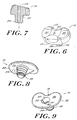
- the superior surface 16 of the tibial bearing insert 12 may optionally include a blind bore 52.
- the blind bore 52 is preferably substantially centrally located and is of a size and shape sufficient to receive a reinforcement pin 54 of the type shown in Figure 4.
- reinforcement pins are well known in the art and may be substantially cylindrically shaped and made of a metal or metal alloy. Such pins may also have knurled or grooved surface features (not shown) as is known in the art.
- bore 52 is cylindrical, having a diameter of about 1 to 12 mm and a depth of about 5 to 75 mm.
- the locking mechanism preferably is a bayonet-type locking mechanism that includes a non-deformable positive surface feature on one of the first or second components 12, 14 to be engaged within a locking channel formed within the other of the first or second components 12, 14.
- a locking channel formed within the other of the first or second components 12, 14.
- at least one access channel which leads to the locking channel, is formed within the component.
- the access channel provides a means by which the positive surface feature may enter the locking channel. Rotation of the component with the positive surface feature causes the positive surface feature to become misaligned with the access channel so that one of the first or second components 12, 14 is positively engaged within the other of the first or second components 12, 14.
- the tibial bearing insert 12 is shown to be the component having a non-deformable positive surface feature 24 formed on the mating stem 22.
- At least one positive surface feature 24 is located on the mating stem 22.
- at least two positive surface features are present on the stem.
- the positive surface features 24 are opposite each other on anterior and posterior sides 13, 15 of the lower portion of mating stem 22.
- the positive surface features 24 protrude from the side wall 30 of the mating stem 22 by a distance in the range of about 0.25 to 8 mm.
- FIGs 5 through 7 and 9 illustrate an embodiment of the invention in which a positive surface 24 feature is formed on the mating stem 22 of the tibial bearing insert 12 and negative surface features are formed within the mating cavity 44 of the tibial tray.
- the positive surface feature can be in the form of a raised knob 56 that is formed on anterior and posterior sides 3, 15 of the mating stem 22.
- the knobs 56 can be substantially rectangularly-shaped, although one of ordinary skill in the art will readily appreciate that other shapes may be employed as well.
- the knobs protrude from the exterior wall of the mating stem by about 0.25 to 8 mm.
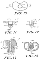
- the knobs 56 may be located on a bottom portion of the mating stem, as shown in Figures 6 and 7, at a top portion of the mating stem as shown in Figure 14, or at intermediate positions.
- the non-deformable positive surface features 24 on the mating stem 22 protrude from the wall of the mating stem 22 to the extent that they prevent the mating stem from being inserted within the mating cavity 44 except through the negative surface features, as discussed below.
- the other dimensions of the positive surface features are not critical and can be readily determined by one of ordinary skill in the art.
- the mating cavity 44 includes negative surface features that cooperate to allow the mating stem 22 to be inserted within the mating cavity and to be secured therein.
- the mating cavity includes opposed axial slots 58 that are formed in side wall 45 of mating cavity 44.
- Axial slots 58 form access channels that enable the mating stem 22 to be inserted within mating cavity 44.
- axial slots 58 are of a sufficient depth to receive the knobs 56 of the mating stem.
- the axial slots 58 should be of a width that enables receipt of the knobs 56, while preventing any significant rotational movement of the knobs 56 when disposed within the axial slots 58.
- the axially oriented slots 58 are disposed on opposed medial and lateral sides of the mating cavity.
- One of ordinary skill in the art can readily determine other suitable placement locations for the knobs 56 and the axial slots 58.
- the axial slots 58 terminate distally at a circumferential groove 60 which serves as a locking channel.
- Circumferential groove 60 like axial slot 58, has dimensions that are sufficient to receive the knobs 56.
- the circumferential groove 60 may be a single groove that extends continuously about the inner circumference of the mating cavity 44. Alternatively, as one of ordinary skill in the art will appreciate, the circumferential groove 60 may be comprise two or more non-continuous groove segments (not shown).
- the knobs 56, axial slots 58 and circumferential groove 60 cooperate to form locking mechanism for the prosthesis system 10.
- This locking mechanism allows rotation of the tibial bearing insert 12 with respect to the tibial tray by travel of the knobs 56 within groove 60.
- the circumferential groove 60 provides positive axial securement of the tibial bearing insert 12 within the tibial tray 14 when the tibial bearing insert is properly mounted within the tibial tray. This is accomplished by engaging the positive surface features (i.e., knobs 56) of the tibial bearing insert 12 within one of the negative surface features (i.e., circumferential groove 60) of the mating cavity.
- the knobs 56 are preferably non-deformable and the relative dimensions of the knobs 56 and groove 60 are such that the knobs 56 are engaged within the groove 60 and cannot be removed from groove 60 except through axial slot 58.
- Circumferential groove 60 preferably is formed as a recess within interior side wall 45 of cavity 44. As such, circumferential groove 60 includes a proximal shoulder 61 or another suitable structure that is effective to maintain the knobs 56 within groove 60.
- knobs 56 allow the knobs 56 to be disposed at proximal and intermediate portions of the mating stem rather than at a distal end as in the embodiment shown in Figures 1 through 9.
- the axial slot 58 will have a shorter length than the embodiments shown in Figures 1 through 9.
- the circumferentially groove 60 will be placed immediately distally of the axial slots 58 and at a more proximal location on the mating cavity.
- the prosthesis system 10 may be assembled as follows. Assuming that the placement of positive and negative surface features is a shown in Figures 1-14, the tibial bearing insert 12 is oriented such that the anterior and posterior surfaces 13, 15 thereof are offset approximately 90° from the anterior and posterior surfaces 17, 19 of the tibial tray. This enables the knobs 56 to be disposed within axial slots 58 of the mating cavity 44. Further, this orientation allows the mating stem 22 of the tibial bearing insert 12 to be inserted within the mating cavity 44. Once the mating stem 22 is fully inserted, the knobs 56 extend beyond the distal end of the axially oriented slots 58 and communicate with the circumferential groove 60. At this point, the tibial bearing insert can be rotated into its proper position in which the posterior and anterior sides of the tibial bearing insert and the tibial tray are aligned with one another.
- the tibial bearing insert and the tibial tray are axially secured to one another. That is, the engagement of the knobs 56 within the circumferential groove 60 prevents axial separation of the components.
- the axially secured tibial bearing insert can withdstand an upwardly directed axial force of at least about 1 kg, and more preferably from about 14 kg to about 90 kg.
- the relative dimensions of the circumferential groove 60 and knob 56 should be such that a clearance fit is achieved. That is, the tibial tray should be free to rotate with little or no friction, but substantially no vertical movement of the tibial bearing insert 12 relative to the tibial tray 24 should exist when the knobs 56 are engaged by circumferential groove 60 and misaligned with slot 58.
- the components of the system 10 of the invention can be made from a variety of known materials.
- the tibial bearing insert typically is made from a polymeric material, such as ultra high molecular weight polyethylene.
- the tibial bearing insert can be made of a variety of known metals and metal alloys that are suitable for implantable prostheses.
Landscapes
- Health & Medical Sciences (AREA)
- Orthopedic Medicine & Surgery (AREA)
- Physical Education & Sports Medicine (AREA)
- Cardiology (AREA)
- Oral & Maxillofacial Surgery (AREA)
- Transplantation (AREA)
- Engineering & Computer Science (AREA)
- Biomedical Technology (AREA)
- Heart & Thoracic Surgery (AREA)
- Vascular Medicine (AREA)
- Life Sciences & Earth Sciences (AREA)
- Animal Behavior & Ethology (AREA)
- General Health & Medical Sciences (AREA)
- Public Health (AREA)
- Veterinary Medicine (AREA)
- Prostheses (AREA)
Claims (14)
- Gelenkprothesensystem mit
einer ersten Komponente (14), die eine obere Befestigungsoberfläche (32) und eine untere Knochenkontaktoberfläche (34) aufweist, wobei die Knochenkontaktoberfläche einen Ankerschaft (39) aufweist, der eine äußere, implantierbare Seite (40), distale Wände (41), eine innere Seite (45) und distale Wände (46) aufweist,
einem Hohlraum (44), der in der oberen Befestigungsoberfläche ausgebildet ist und sich in den Ankerschaft erstreckt, wobei der Hohlraum (44) durch die innere Seite (45) und die distalen Wände (46) des Ankerschaftes (39) gebildet ist,
einer zweiten Komponente (12), die eine obere Gelenkoberfläche (16) und eine untere Oberfläche (34) aufweist, die auf der Befestigungsoberfläche der ersten Komponente (14) befestigbar ist, wobei die untere Oberfläche einen passenden Schaft (22) aufweist, der in dem Hohlraum (44) befestigbar ist und eine Form und eine Größe aufweist, die zu dem Hohlraum komplementär sind,
einem selektiv einrastbaren Verriegelungsmechanismus, der zumindest ein positives Oberflächenmerkmal (24) auf entweder dem passenden Schaft oder dem Hohlraum und zumindest ein mit diesem Merkmal zusammenwirkendes negatives Oberflächenmerkmal auf dem anderen Teil, dem passenden Schaft oder dem Hohlraum, aufweist,
dadurch gekennzeichnet, daß das negative Oberflächenmerkmal eine Verriegelungsnut (60) und eine Zugangsnut (58), die mit der Verriegelungsnut verbunden ist, aufweist, und
daß der Verriegelungsmechanismus angeordnet ist, um zu ermöglichen, daß der passende Schaft (22) nur dann in den Hohlraum passt, wenn das positive Oberflächenmerkmal (24) mit der Zugangsnut (58) ausgerichtet ist, wobei der Verriegelungsmechanismus, wenn er eingerastet ist, wirksam ist, um eine Drehung der zweiten Komponente relativ zu der ersten Komponente zu ermöglichen, wodurch das positive Oberflächenmerkmal (24) so verschoben wird, daß es nicht mehr mit der Zugangsnut (58) ausgerichtet ist, so daß eine formschlüßige axiale Befestigung der zweiten Komponente an der ersten Komponente erzeugt wird. - System nach Anspruch 1, dadurch gekennzeichnet, daß die erste Komponente eine tibiale Schale und die zweite Komponente ein tibialer Lagereinsatz ist.
- System nach Anspruch 2, dadurch gekennzeichnet, daß das System des weiteren aufweist:eine axiale Bohrung (52), die in der oberen Oberfläche des tibialen Lagereinsatzes ausgebildet ist und sich in den passenden Schaft erstreckt, undeinen Verstärkungsstift (54), der in der axialen Bohrung in einer Reibungspassung derart befestigbar ist, daß ein proximaler Abschnitt des Verstärkungsstiftes nicht über die obere Oberfläche des tibialen Lagereinsatzes hinausragt.
- System nach Anspruch 1, dadurch gekennzeichnet, daß zumindest eines der positiven O-berflächenmerkmale (24) auf einer äußeren Seitenwand des passenden Schaftes ausgebildet ist und daß zumindest ein negatives Oberflächenmerkmal auf der inneren Seitenwand des Hohlraumes angeordnet ist.
- System nach Anspruch 4, dadurch gekennzeichnet, daß zwei positive Oberflächenmerkmale (24) einander gegenüberliegend auf der äußeren Seitenwand des passenden Schaftes angeordnet sind.
- System nach Anspruch 4, dadurch gekennzeichnet, daß der Verriegelungsmechanismus umfaßt:die Zugangsnut, die zumindest einen axialen Schlitz (58) aufweist, der in der inneren Seitenwand des Hohlraums gebildet ist, unddie Verriegelungsnut, die eine umlaufende Nut (60) aufweist, die in dem Hohlraum distal zu und in Verbindung mit dem axialen Schlitz ausgebildet ist.
- System nach Anspruch 6, dadurch gekennzeichnet, daß die umlaufende Nut (60) angeordnet ist, um beim vollständigen Einsetzen des passenden Schaftes in den Hohlraum das positive Oberflächenmerkmal aufzunehmen.
- System nach Anspruch 1, dadurch gekennzeichnet, daß der passende Schaft (22) ein längliches Teil ist.
- System nach Anspruch 8, dadurch gekennzeichnet, daß der passende Schaft (22) eine Länge in dem Bereich von ungefähr 4-75 mm aufweist.
- System nach Anspruch 9, dadurch gekennzeichnet, daß der Hohlraum (44) eine Tiefe in dem Bereich von ungefähr 5-75 mm aufweist.
- System nach Anspruch 1, dadurch gekennzeichnet, daß der Hohlraum (44) einen nominellen Durchmesser aufweist, der sich von einem größten nominellen Durchmesser an einem proximalen Abschnitt des Hohlraums zu einem kleinsten nominellen Durchmesser an einem distalen Abschnitt des Hohlraums verjüngt.
- System nach Anspruch 11, dadurch gekennzeichnet, daß sich der nominelle Durchmesser des Hohlraums (44) mit einem Winkel verjüngt, der in dem Bereich von ungefähr 0.25° bis 5° liegt.
- System nach Anspruch 11, dadurch gekennzeichnet, daß der passende Schaft (22) einen nominellen Durchmesser aufweist, der sich von einem größten nominellen Durchmesser an einem proximalen Abschnitt des passenden Schaftes zu einem kleinsten nominellen Durchmesser an einem distalen Abschnitt des Schaftes verjüngt.
- System nach Anspruch 13, dadurch gekennzeichnet, daß die Form und die nominellen Durchmesser des passenden Schaftes (22) und der Hohlraum (44) komplementär zueinander sind.
Applications Claiming Priority (2)
| Application Number | Priority Date | Filing Date | Title |
|---|---|---|---|
| US937965 | 1997-09-25 | ||
| US08/937,965 US6010534A (en) | 1997-09-25 | 1997-09-25 | Rotatable tibial prosthesis with keyed axial securement |
Publications (3)
| Publication Number | Publication Date |
|---|---|
| EP0904748A2 EP0904748A2 (de) | 1999-03-31 |
| EP0904748A3 EP0904748A3 (de) | 2000-01-05 |
| EP0904748B1 true EP0904748B1 (de) | 2005-12-21 |
Family
ID=25470644
Family Applications (1)
| Application Number | Title | Priority Date | Filing Date |
|---|---|---|---|
| EP98307768A Expired - Lifetime EP0904748B1 (de) | 1997-09-25 | 1998-09-24 | Gelenkprothesensystem mit einer in Längsrichtung verschlossenen drehbaren Komponente |
Country Status (3)
| Country | Link |
|---|---|
| US (1) | US6010534A (de) |
| EP (1) | EP0904748B1 (de) |
| DE (1) | DE69832861T2 (de) |
Cited By (1)
| Publication number | Priority date | Publication date | Assignee | Title |
|---|---|---|---|---|
| US9211189B2 (en) | 2008-11-14 | 2015-12-15 | Zimmer, Inc. | Transiently mobile tibial engagement |
Families Citing this family (63)
| Publication number | Priority date | Publication date | Assignee | Title |
|---|---|---|---|---|
| US6296666B1 (en) | 2000-03-13 | 2001-10-02 | Encore Medical Corporation | Mobile bearing knee with center post |
| US6447549B1 (en) | 2000-10-06 | 2002-09-10 | Sulzer Orthopedics Inc. | Modular knee prosthesis system |
| US6558426B1 (en) | 2000-11-28 | 2003-05-06 | Medidea, Llc | Multiple-cam, posterior-stabilized knee prosthesis |
| US6355037B1 (en) | 2000-12-05 | 2002-03-12 | Smith & Nephew, Inc. | Apparatus and method of external skeletal support allowing for internal-external rotation |
| US20020120340A1 (en) | 2001-02-23 | 2002-08-29 | Metzger Robert G. | Knee joint prosthesis |
| US7497874B1 (en) | 2001-02-23 | 2009-03-03 | Biomet Manufacturing Corp. | Knee joint prosthesis |
| US6962607B2 (en) * | 2001-06-30 | 2005-11-08 | Depuy Products, Inc. | Joint replacement prosthesis component with non linear insert |
| CA2475078C (en) * | 2002-02-20 | 2010-05-04 | Thomas M. Coon | Knee arthroplasty prosthesis and method |
| DE10221272A1 (de) * | 2002-05-14 | 2003-11-27 | Peter Brehm | Tibiakomponente und Gleitplatte einer Kniegelenkendoprothese |
| EP1601316A1 (de) * | 2003-02-04 | 2005-12-07 | Zimmer Austin, Inc. | Drehbares/nicht drehbares tibiaplatten-/einsatzsystem |
| US20050246028A1 (en) * | 2004-04-28 | 2005-11-03 | Buechel-Pappas Trust | Prosthetic knee |
| CN101351172B (zh) * | 2005-10-31 | 2013-10-23 | 德普伊产品公司 | 模块化固定和活动承座假体系统 |
| US7691149B2 (en) * | 2006-05-15 | 2010-04-06 | Biomet Manufacturing Corp. | Porous titanium modular revision patella system |
| US7740662B2 (en) | 2006-10-13 | 2010-06-22 | Depuy Products, Inc. | Mobile/fixed prosthetic knee systems |
| US20080091273A1 (en) * | 2006-10-13 | 2008-04-17 | Hazebrouck Stephen A | Mobile/fixed prosthetic knee systems |
| US20080091272A1 (en) * | 2006-10-13 | 2008-04-17 | Aram Luke J | Mobile/fixed prosthetic knee systems |
| US20080114463A1 (en) * | 2006-10-13 | 2008-05-15 | Auger Daniel D | Mobile/fixed prosthetic knee systems |
| JP5448842B2 (ja) * | 2007-01-10 | 2014-03-19 | バイオメト マニファクチャリング コーポレイション | 膝関節プロテーゼシステムおよび埋込み方法 |
| US8187280B2 (en) | 2007-10-10 | 2012-05-29 | Biomet Manufacturing Corp. | Knee joint prosthesis system and method for implantation |
| US8562616B2 (en) | 2007-10-10 | 2013-10-22 | Biomet Manufacturing, Llc | Knee joint prosthesis system and method for implantation |
| US8163028B2 (en) * | 2007-01-10 | 2012-04-24 | Biomet Manufacturing Corp. | Knee joint prosthesis system and method for implantation |
| US8328873B2 (en) | 2007-01-10 | 2012-12-11 | Biomet Manufacturing Corp. | Knee joint prosthesis system and method for implantation |
| US8328874B2 (en) * | 2007-03-30 | 2012-12-11 | Depuy Products, Inc. | Mobile bearing assembly |
| US8142510B2 (en) * | 2007-03-30 | 2012-03-27 | Depuy Products, Inc. | Mobile bearing assembly having a non-planar interface |
| US8147558B2 (en) * | 2007-03-30 | 2012-04-03 | Depuy Products, Inc. | Mobile bearing assembly having multiple articulation interfaces |
| US8147557B2 (en) * | 2007-03-30 | 2012-04-03 | Depuy Products, Inc. | Mobile bearing insert having offset dwell point |
| US8764841B2 (en) * | 2007-03-30 | 2014-07-01 | DePuy Synthes Products, LLC | Mobile bearing assembly having a closed track |
| US8632600B2 (en) | 2007-09-25 | 2014-01-21 | Depuy (Ireland) | Prosthesis with modular extensions |
| US8128703B2 (en) | 2007-09-28 | 2012-03-06 | Depuy Products, Inc. | Fixed-bearing knee prosthesis having interchangeable components |
| US9204967B2 (en) | 2007-09-28 | 2015-12-08 | Depuy (Ireland) | Fixed-bearing knee prosthesis having interchangeable components |
| US9168145B2 (en) | 2008-06-30 | 2015-10-27 | Depuy (Ireland) | Posterior stabilized orthopaedic knee prosthesis having controlled condylar curvature |
| US8187335B2 (en) | 2008-06-30 | 2012-05-29 | Depuy Products, Inc. | Posterior stabilized orthopaedic knee prosthesis having controlled condylar curvature |
| US9119723B2 (en) | 2008-06-30 | 2015-09-01 | Depuy (Ireland) | Posterior stabilized orthopaedic prosthesis assembly |
| US8236061B2 (en) | 2008-06-30 | 2012-08-07 | Depuy Products, Inc. | Orthopaedic knee prosthesis having controlled condylar curvature |
| US8828086B2 (en) | 2008-06-30 | 2014-09-09 | Depuy (Ireland) | Orthopaedic femoral component having controlled condylar curvature |
| US8192498B2 (en) | 2008-06-30 | 2012-06-05 | Depuy Products, Inc. | Posterior cructiate-retaining orthopaedic knee prosthesis having controlled condylar curvature |
| US8206451B2 (en) | 2008-06-30 | 2012-06-26 | Depuy Products, Inc. | Posterior stabilized orthopaedic prosthesis |
| US8696754B2 (en) * | 2008-09-03 | 2014-04-15 | Biomet Manufacturing, Llc | Revision patella prosthesis |
| US9011547B2 (en) * | 2010-01-21 | 2015-04-21 | Depuy (Ireland) | Knee prosthesis system |
| EP3332748B1 (de) | 2010-07-24 | 2019-08-14 | Zimmer, Inc. | Asymmetrische tibiakomponenten für eine knieprothese |
| US8628580B2 (en) | 2010-07-24 | 2014-01-14 | Zimmer, Inc. | Tibial prosthesis |
| WO2012034033A1 (en) | 2010-09-10 | 2012-03-15 | Zimmer, Inc. | Motion facilitating tibial components for a knee prosthesis |
| US8287601B2 (en) | 2010-09-30 | 2012-10-16 | Depuy Products, Inc. | Femoral component of a knee prosthesis having an angled cement pocket |
| US8317870B2 (en) | 2010-09-30 | 2012-11-27 | Depuy Products, Inc. | Tibial component of a knee prosthesis having an angled cement pocket |
| US8603101B2 (en) | 2010-12-17 | 2013-12-10 | Zimmer, Inc. | Provisional tibial prosthesis system |
| US8690954B2 (en) | 2011-11-18 | 2014-04-08 | Zimmer, Inc. | Tibial bearing component for a knee prosthesis with improved articular characteristics |
| EP3037068B1 (de) | 2011-11-21 | 2020-07-29 | Zimmer, Inc. | Tibiaplateau mit asymmetrischer anordnung von befestigungsstrukturen |
| US9011444B2 (en) | 2011-12-09 | 2015-04-21 | Howmedica Osteonics Corp. | Surgical reaming instrument for shaping a bone cavity |
| US9149282B2 (en) | 2011-12-30 | 2015-10-06 | Howmedica Osteonics Corp. | Systems and methods for preparing bone voids to receive a prosthesis |
| AU2012368262B2 (en) | 2012-01-30 | 2017-06-29 | Zimmer, Inc. | Asymmetric tibial components for a knee prosthesis |
| US8721733B2 (en) * | 2012-05-14 | 2014-05-13 | Depuy (Ireland) | Prosthesis kit with finned sleeve |
| US8961612B2 (en) | 2012-08-30 | 2015-02-24 | Biomet Manufacturing, Llc | Knee component having orbital interface boss |
| US9526513B2 (en) | 2013-03-13 | 2016-12-27 | Howmedica Osteonics Corp. | Void filling joint prosthesis and associated instruments |
| US9925052B2 (en) | 2013-08-30 | 2018-03-27 | Zimmer, Inc. | Method for optimizing implant designs |
| EP3354233B1 (de) | 2014-05-12 | 2019-10-02 | Integra LifeSciences Corporation | Fussgelenksvollprothese |
| US10149763B2 (en) | 2015-01-12 | 2018-12-11 | Howmedica Osteonics Corp. | Multipurpose void filling prosthesis |
| US10278827B2 (en) | 2015-09-21 | 2019-05-07 | Zimmer, Inc. | Prosthesis system including tibial bearing component |
| US10231840B2 (en) | 2016-07-27 | 2019-03-19 | Howmedica Osteonics Corp. | Low profile tibial baseplate with fixation members |
| ES2878003T3 (es) | 2017-03-10 | 2021-11-18 | Zimmer Inc | Prótesis tibial con característica de afianzamiento para un componente de apoyo tibial |
| EP4487819B1 (de) | 2017-05-12 | 2026-03-25 | Zimmer, Inc. | Femurprothesen mit vergrösserungs- und verkleinerungskapazität |
| US11426282B2 (en) | 2017-11-16 | 2022-08-30 | Zimmer, Inc. | Implants for adding joint inclination to a knee arthroplasty |
| US10835380B2 (en) | 2018-04-30 | 2020-11-17 | Zimmer, Inc. | Posterior stabilized prosthesis system |
| AU2019375490B2 (en) * | 2018-11-09 | 2021-09-02 | Signature Orthopaedics Europe Ltd | A revision knee system |
Family Cites Families (44)
| Publication number | Priority date | Publication date | Assignee | Title |
|---|---|---|---|---|
| US4219893A (en) * | 1977-09-01 | 1980-09-02 | United States Surgical Corporation | Prosthetic knee joint |
| US4301553A (en) * | 1975-08-15 | 1981-11-24 | United States Surgical Corporation | Prosthetic knee joint |
| US4136405A (en) * | 1977-04-29 | 1979-01-30 | Zimmer U.S.A. | Rotational offset knee prosthesis |
| JPH0553501B2 (de) * | 1978-03-10 | 1993-08-10 | Biomedical Eng Corp | |
| EP0046926B1 (de) * | 1980-09-03 | 1985-12-11 | Waldemar Link (GmbH & Co.) | Kniegelenk-Endoprothese |
| DE3119841A1 (de) * | 1981-05-19 | 1982-12-16 | GMT GESELLSCHAFT FüR MEDIZINISCHE TECHNIK MBH | Endoprothese eines kniegelenks |
| DE3136636A1 (de) * | 1981-09-16 | 1983-03-31 | Waldemar Link (Gmbh & Co), 2000 Hamburg | Tibiaplateau aus kunststoff mit einer unterlagplatte aus hartem material |
| DE3138848C2 (de) * | 1981-09-30 | 1987-02-05 | GMT GESELLSCHAFT FüR MEDIZINISCHE TECHNIK MBH | Endoprothese zum Ersatz eines stabförmigen Knochens |
| DE3431645A1 (de) * | 1984-08-29 | 1986-03-13 | GMT GESELLSCHAFT FüR MEDIZINISCHE TECHNIK MBH | Endoprothese |
| SE450460B (sv) * | 1984-11-28 | 1987-06-29 | Albrektsson Bjoern | Anordning vid konstgjord menisk for en kneledsprotes |
| GB8432267D0 (en) * | 1984-12-20 | 1985-01-30 | Thackray C F Ltd | Knee prosthesis |
| FR2601873B1 (fr) * | 1986-07-25 | 1994-07-01 | Cuilleron J | Prothese totale intracondylienne du genou |
| US4888021A (en) * | 1988-02-02 | 1989-12-19 | Joint Medical Products Corporation | Knee and patellar prosthesis |
| US5011496A (en) * | 1988-02-02 | 1991-04-30 | Joint Medical Products Corporation | Prosthetic joint |
| FR2631814A1 (fr) * | 1988-05-31 | 1989-12-01 | Scernp | Prothese a glissement pour le genou |
| US5171283A (en) * | 1989-07-11 | 1992-12-15 | Biomedical Engineering Trust | Compound shape rotating bearing |
| US5059216A (en) * | 1989-09-29 | 1991-10-22 | Winters Thomas F | Knee joint replacement apparatus |
| GB9005496D0 (en) * | 1990-03-12 | 1990-05-09 | Howmedica | Tibial component for a replacement knee prosthesis and total knee prosthesis incorporating such a component |
| US5370701A (en) * | 1990-09-28 | 1994-12-06 | Arch Development Corporation | Rotating/sliding contrained prosthetic knee |
| US5071438A (en) * | 1990-11-07 | 1991-12-10 | Intermedics Orthopedics, Inc. | Tibial prothesis with pivoting articulating surface |
| DE69128961T2 (de) * | 1990-11-14 | 1998-10-08 | Arch Development Corp., Chicago, Ill. | Verbesserte knieprothese mit beweglichem lager |
| GB9102348D0 (en) * | 1991-02-04 | 1991-03-20 | Inst Of Orthopaedics The | Prosthesis for knee replacement |
| EP0682925B1 (de) * | 1991-06-17 | 2001-09-12 | André Bähler | Gelenkprothese, insbesondere Kniegelenkprothese |
| US5282868A (en) * | 1991-06-17 | 1994-02-01 | Andre Bahler | Prosthetic arrangement for a complex joint, especially knee joint |
| US5395401A (en) * | 1991-06-17 | 1995-03-07 | Bahler; Andre | Prosthetic device for a complex joint |
| DE4128171C1 (de) * | 1991-08-24 | 1993-04-01 | Aesculap Ag, 7200 Tuttlingen, De | |
| ATE176145T1 (de) * | 1992-01-14 | 1999-02-15 | Sulzer Orthopaedie Ag | Meniskusplattform zu künstlichem kniegelenk |
| NZ243181A (en) * | 1992-04-23 | 1994-10-26 | Michael John Pappas | Prosthetic joint with guide means to limit articulation of a first element and bearing means to two degrees of freedom |
| DE9212879U1 (de) * | 1992-09-24 | 1994-01-27 | Waldemar Link GmbH & Co, 22339 Hamburg | Kniegelenkendoprothese zum Ersatz der Schienbein-Gelenkflächen |
| US5370699A (en) * | 1993-01-21 | 1994-12-06 | Orthomet, Inc. | Modular knee joint prosthesis |
| ATE167620T1 (de) * | 1993-04-05 | 1998-07-15 | Procom S A | Prothesenteile zum aufbau eines kniegelenks |
| GB9314832D0 (en) * | 1993-07-16 | 1993-09-01 | Walker Peter S | Prostheses for knee replacement |
| IT1264820B1 (it) * | 1993-07-28 | 1996-10-10 | Cremascoli G Srl | Protesi totale di ginocchio protesi totale di ginocchio |
| US5755802A (en) * | 1993-12-30 | 1998-05-26 | Bruno E. Gerber | Knee-joint endoprosthesis |
| US5489311A (en) * | 1994-01-21 | 1996-02-06 | Joint Medical Products Corporation | Prosthesis with orientable bearing surface |
| DE4409787A1 (de) * | 1994-03-22 | 1995-09-28 | Alphanorm Medizintechnik Gmbh | Kniegelenkprothese |
| GB9405883D0 (en) * | 1994-03-24 | 1994-05-11 | Corin Medical Ltd | Prosthesis assembly |
| FR2719466B1 (fr) * | 1994-05-04 | 1997-06-06 | Ysebaert Sa | Prothèse du genou à ménisque mobile. |
| FR2721820B1 (fr) * | 1994-06-30 | 1996-12-13 | Ysebaert Sa | Articulation prothetique de genou, notamment prothese unicompartimentale de genou, ou prothese de la rotule |
| GB9415180D0 (en) * | 1994-07-28 | 1994-09-21 | Walker Peter S | Stabilised mobile bearing knee |
| FR2726174B1 (fr) * | 1994-10-26 | 1997-04-04 | Cornic Michel | Prothese d'articulation du genou |
| FR2728782B1 (fr) * | 1994-12-30 | 1998-10-16 | Jbs Sa | Prothese de genou |
| US5683468A (en) * | 1995-03-13 | 1997-11-04 | Pappas; Michael J. | Mobile bearing total joint replacement |
| US5871543A (en) * | 1996-02-23 | 1999-02-16 | Hofmann; Aaron A. | Tibial prosthesis with mobile bearing member |
-
1997
- 1997-09-25 US US08/937,965 patent/US6010534A/en not_active Expired - Lifetime
-
1998
- 1998-09-24 EP EP98307768A patent/EP0904748B1/de not_active Expired - Lifetime
- 1998-09-24 DE DE69832861T patent/DE69832861T2/de not_active Expired - Lifetime
Cited By (1)
| Publication number | Priority date | Publication date | Assignee | Title |
|---|---|---|---|---|
| US9211189B2 (en) | 2008-11-14 | 2015-12-15 | Zimmer, Inc. | Transiently mobile tibial engagement |
Also Published As
| Publication number | Publication date |
|---|---|
| DE69832861T2 (de) | 2006-08-17 |
| EP0904748A2 (de) | 1999-03-31 |
| US6010534A (en) | 2000-01-04 |
| EP0904748A3 (de) | 2000-01-05 |
| DE69832861D1 (de) | 2006-01-26 |
Similar Documents
| Publication | Publication Date | Title |
|---|---|---|
| EP0904748B1 (de) | Gelenkprothesensystem mit einer in Längsrichtung verschlossenen drehbaren Komponente | |
| EP0904750B1 (de) | Drehbare Gelenkprothese mit axialer Fixierung | |
| EP0970667B1 (de) | Drehbare und verschiebbare Gelenkprothese mit hinterer Stabilität | |
| EP0904749B1 (de) | Gelenkprothese mit kontrollierter Drehbewegung | |
| EP1025818B1 (de) | Modulares Gelenkprothesensystem | |
| EP1023881B1 (de) | Modularer tibialer Einsatz für ein prosthetisches System | |
| EP0980679B1 (de) | Femurteil einer modularen Knieprothese | |
| EP0986994B1 (de) | In einem Gehäuse mit Innengewinde befestigter femoraler Schaft für eine modulare Knieprothese | |
| EP0797417B1 (de) | Knieprothese mit einsätzen | |
| EP1238635B1 (de) | Eine Reibvorrichtung | |
| US5019103A (en) | Tibial wedge system | |
| US5766257A (en) | Artificial joint having natural load transfer | |
| US6139581A (en) | Posterior compensation tibial tray | |
| EP0985386B1 (de) | Femoraler Schaftbausatz für eine modulare Knieprothese | |
| US20090149963A1 (en) | Prosthesis assembly including angle and position adaptors | |
| EP1398006A2 (de) | Gelenkprothese mit doppelter Befestigung | |
| US20050154470A1 (en) | Modular phrosthesis assembly including tapered adjustments | |
| EP3049027B1 (de) | Reverse knieprothese |
Legal Events
| Date | Code | Title | Description |
|---|---|---|---|
| PUAI | Public reference made under article 153(3) epc to a published international application that has entered the european phase |
Free format text: ORIGINAL CODE: 0009012 |
|
| AK | Designated contracting states |
Kind code of ref document: A2 Designated state(s): DE GB |
|
| AX | Request for extension of the european patent |
Free format text: AL;LT;LV;MK;RO;SI |
|
| PUAL | Search report despatched |
Free format text: ORIGINAL CODE: 0009013 |
|
| AK | Designated contracting states |
Kind code of ref document: A3 Designated state(s): AT BE CH CY DE DK ES FI FR GB GR IE IT LI LU MC NL PT SE |
|
| AX | Request for extension of the european patent |
Free format text: AL;LT;LV;MK;RO;SI |
|
| 17P | Request for examination filed |
Effective date: 20000613 |
|
| AKX | Designation fees paid |
Free format text: DE GB |
|
| RAP1 | Party data changed (applicant data changed or rights of an application transferred) |
Owner name: DEPUY PRODUCTS, INC. |
|
| RAP1 | Party data changed (applicant data changed or rights of an application transferred) |
Owner name: DEPUY PRODUCTS, INC. |
|
| 17Q | First examination report despatched |
Effective date: 20040428 |
|
| GRAP | Despatch of communication of intention to grant a patent |
Free format text: ORIGINAL CODE: EPIDOSNIGR1 |
|
| RIC1 | Information provided on ipc code assigned before grant |
Ipc: 7A 61F 2/38 B Ipc: 7A 61F 2/30 A |
|
| RTI1 | Title (correction) |
Free format text: JOINT PROSTHESIS SYSTEM WITH A ROTATABLE COMPONENT HAVING A KEYED AXIAL SECUREMENT |
|
| GRAS | Grant fee paid |
Free format text: ORIGINAL CODE: EPIDOSNIGR3 |
|
| GRAA | (expected) grant |
Free format text: ORIGINAL CODE: 0009210 |
|
| AK | Designated contracting states |
Kind code of ref document: B1 Designated state(s): DE GB |
|
| REG | Reference to a national code |
Ref country code: GB Ref legal event code: FG4D |
|
| REF | Corresponds to: |
Ref document number: 69832861 Country of ref document: DE Date of ref document: 20060126 Kind code of ref document: P |
|
| PLBE | No opposition filed within time limit |
Free format text: ORIGINAL CODE: 0009261 |
|
| STAA | Information on the status of an ep patent application or granted ep patent |
Free format text: STATUS: NO OPPOSITION FILED WITHIN TIME LIMIT |
|
| 26N | No opposition filed |
Effective date: 20060922 |
|
| PGFP | Annual fee paid to national office [announced via postgrant information from national office to epo] |
Ref country code: DE Payment date: 20130918 Year of fee payment: 16 |
|
| PGFP | Annual fee paid to national office [announced via postgrant information from national office to epo] |
Ref country code: GB Payment date: 20130918 Year of fee payment: 16 |
|
| REG | Reference to a national code |
Ref country code: DE Ref legal event code: R119 Ref document number: 69832861 Country of ref document: DE |
|
| GBPC | Gb: european patent ceased through non-payment of renewal fee |
Effective date: 20140924 |
|
| PG25 | Lapsed in a contracting state [announced via postgrant information from national office to epo] |
Ref country code: DE Free format text: LAPSE BECAUSE OF NON-PAYMENT OF DUE FEES Effective date: 20150401 Ref country code: GB Free format text: LAPSE BECAUSE OF NON-PAYMENT OF DUE FEES Effective date: 20140924 |