EP0970475B1 - Haltevorrichtung für computer-speicherlaufwerke - Google Patents
Haltevorrichtung für computer-speicherlaufwerke Download PDFInfo
- Publication number
- EP0970475B1 EP0970475B1 EP98928054A EP98928054A EP0970475B1 EP 0970475 B1 EP0970475 B1 EP 0970475B1 EP 98928054 A EP98928054 A EP 98928054A EP 98928054 A EP98928054 A EP 98928054A EP 0970475 B1 EP0970475 B1 EP 0970475B1
- Authority
- EP
- European Patent Office
- Prior art keywords
- wall protrusion
- retaining device
- wall
- chassis
- screw
- Prior art date
- Legal status (The legal status is an assumption and is not a legal conclusion. Google has not performed a legal analysis and makes no representation as to the accuracy of the status listed.)
- Expired - Lifetime
Links
Images
Classifications
-
- G—PHYSICS
- G11—INFORMATION STORAGE
- G11B—INFORMATION STORAGE BASED ON RELATIVE MOVEMENT BETWEEN RECORD CARRIER AND TRANSDUCER
- G11B33/00—Constructional parts, details or accessories not provided for in the other groups of this subclass
- G11B33/12—Disposition of constructional parts in the apparatus, e.g. of power supply, of modules
- G11B33/125—Disposition of constructional parts in the apparatus, e.g. of power supply, of modules the apparatus comprising a plurality of recording/reproducing devices, e.g. modular arrangements, arrays of disc drives
- G11B33/127—Mounting arrangements of constructional parts onto a chassis
- G11B33/128—Mounting arrangements of constructional parts onto a chassis of the plurality of recording/reproducing devices, e.g. disk drives, onto a chassis
-
- G—PHYSICS
- G06—COMPUTING OR CALCULATING; COUNTING
- G06F—ELECTRIC DIGITAL DATA PROCESSING
- G06F1/00—Details not covered by groups G06F3/00 - G06F13/00 and G06F21/00
- G06F1/16—Constructional details or arrangements
- G06F1/18—Packaging or power distribution
- G06F1/183—Internal mounting support structures, e.g. for supporting printed circuit boards
- G06F1/184—Mounting of motherboards
-
- G—PHYSICS
- G06—COMPUTING OR CALCULATING; COUNTING
- G06F—ELECTRIC DIGITAL DATA PROCESSING
- G06F1/00—Details not covered by groups G06F3/00 - G06F13/00 and G06F21/00
- G06F1/16—Constructional details or arrangements
- G06F1/18—Packaging or power distribution
- G06F1/183—Internal mounting support structures, e.g. for supporting printed circuit boards
- G06F1/187—Mounting of fixed or removable disk drives
Definitions
- the invention relates to a holding device for computer storage drives according to the features of the preamble of the claim 1.
- the present invention is therefore based on the object for mounting storage drive carriers in one arranged in a computer case cage-like Chassis as simple as possible, easy to assemble solution Find.
- the advantage the holding device according to the invention is that the drive carrier from one side by means of a single one Screw free of play and, based on the direction of insertion, exactly can be aligned aligned.
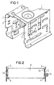
- Figure 1 shows a perspective cage-like Chassis 1 for receiving at least two superimposed ones Storage drive carrier.
- Side walls 2, 3 of the chassis 1 are several Strip-like guide tabs 4 punched out and at right angles bent inwards. They serve as a requirement for the between the two side walls 2, 3 of the chassis can be inserted Storage drive carrier.
- Storage drive carrier For a safe circulation over the entire
- the length of the storage drive carrier is per slot each side wall 2, 3 two guide tabs 4 are provided.
- On one of the two side walls, for example on the right side wall 2, are laterally offset to these guide tabs 4 inward wall projections 5 provided that in the embodiment shown as oblique inwardly inclined, largely flat surfaces are.
- These wall projections 5 are each in the area of threaded holes provided on the side surfaces of the drive carriers arranged.
- the wall projections 5 therefore each have a recess 6 for an externally attachable Screw on.
- the function of these wall projections 5 is in Connection with the description of Figure 2 explained in more detail become.
- On the inside of the other side wall 3 one or more spring elements 7 are provided, which are preferably from the sheet material of the side wall 3 in one Stamping and embossing are formed. One in each Installation space is thus inserted on the one hand by the spring elements 7 and on the other hand by the Wall projections 5 kept free of play.
- FIG. 2 each shows a section of the side walls 2, 3 of the chassis 1 shown in Figure 1 in the area of a slot for a storage drive carrier 8.
- the attachment takes place via a single one, in the area of a wall projection 5 engaging screw 9, which in a threaded bore on the Side surface of the drive carrier 8 is screwed. there the drive carrier 8 is tightened and parallel to the Inserting direction extending support edge 10 of the wall projection 5 aligned.
- the provided on the side wall 3 Spring elements 7 cause on the one hand that the drive carrier between the spring elements 7 and the wall projection 5 without play is held, and on the other hand they prevent the Tightening the screw 9 an undesirable twisting of the Drive carrier 8 from the horizontal position.
- the wall projection 5 is made in a stamping process from the material of the side wall 2 shaped. He can, as shown, from an obliquely inward inclined, essentially flat surface, the upper Limitation serves as a supporting edge 10.
- the ledge can but also designed as an at least partially curved support surface his.
Landscapes
- Engineering & Computer Science (AREA)
- Theoretical Computer Science (AREA)
- Computer Hardware Design (AREA)
- Power Engineering (AREA)
- Human Computer Interaction (AREA)
- Physics & Mathematics (AREA)
- General Engineering & Computer Science (AREA)
- General Physics & Mathematics (AREA)
- Casings For Electric Apparatus (AREA)
- Mounting Components In General For Electric Apparatus (AREA)
- Automatic Disk Changers (AREA)
Description
- Figur 1
- ein käfigartiges Chassis zur Aufnahme von Speicherlaufwerksträgern im perspektivischer Darstellung und
- Figur 2
- die Befestigung des Speicherlaufwerkträgers in einer Anordnung nach Figur 1 in schematischer Schnittdarstellung.
Claims (4)
- Haltevorrichtung für Computer-Speicherlaufwerke, bestehend aus einem rechteckigen, käfigartigen Chassis (1), das an gegenüberliegenden Seitenwänden (2, 3) nach innen gerichtete Führungselemente zur Aufnahme wenigstens eines horizontal einschiebbaren und mittels Schraubverbindung befestigbaren Laufwerkträgers (8) aufweist,
dadurch gekennzeichnet, dass an einer der beiden Seitenwände (2,3) des Chassis (1) für jeden Einbauplatz wenigstens ein nach innen gerichteter Wandvorsprung (5) vorgesehen ist, der eine parallel zur Einschubrichtung verlaufende Stützkante (10) aufweist, dass der Wandvorsprung (5) im Bereich der Gewindebohrung der sich am Wandvorsprung (5) abstützenden Seitenfläche des Laufwerkträgers (8) eine Aussparung (6) für eine von aussen ansetzbare Schraube (9) aufweist und dass an der gegenüberliegenden Seitenwand (3) Federelemente (7) vorgesehen sind, so dass der mittels der Schraube (9) an den Wandvorsprung (5) gezogene Laufwerksträger (8) parallel zur Einschubrichtung spielfrei und verdrehungssicher befestigt ist. - Haltevorrichtung nach Anspruch 1,
dadurch gekennzeichnet, dass der Wandvorsprung (5) als schräg nach innen geneigte weitgehend ebene Fläche ausgebildet ist, deren obere Begrenzung als Stützkante (10) dient. - Haltevorrichtung nach Anspruch 2,
dadurch gekennzeichnet, dass der Wandvorsprung als rechteckige Fläche ausgebildet ist. - Haltevorrichtung nach einem der vorhergehenden Ansprüche,
dadurch gekennzeichnet, dass der Wandvorsprung durch einen Prägevorgang gebildet ist.
Applications Claiming Priority (3)
| Application Number | Priority Date | Filing Date | Title |
|---|---|---|---|
| DE29705507U DE29705507U1 (de) | 1997-03-26 | 1997-03-26 | Haltevorrichtung für Computer-Speicherlaufwerke |
| DE29705507U | 1997-03-26 | ||
| PCT/DE1998/000848 WO1998043246A2 (de) | 1997-03-26 | 1998-03-23 | Haltevorrichtung für computer-speicherlaufwerke |
Publications (2)
| Publication Number | Publication Date |
|---|---|
| EP0970475A2 EP0970475A2 (de) | 2000-01-12 |
| EP0970475B1 true EP0970475B1 (de) | 2002-06-26 |
Family
ID=8038096
Family Applications (1)
| Application Number | Title | Priority Date | Filing Date |
|---|---|---|---|
| EP98928054A Expired - Lifetime EP0970475B1 (de) | 1997-03-26 | 1998-03-23 | Haltevorrichtung für computer-speicherlaufwerke |
Country Status (5)
| Country | Link |
|---|---|
| US (1) | US6341059B1 (de) |
| EP (1) | EP0970475B1 (de) |
| JP (1) | JP2001519075A (de) |
| DE (2) | DE29705507U1 (de) |
| WO (1) | WO1998043246A2 (de) |
Families Citing this family (9)
| Publication number | Priority date | Publication date | Assignee | Title |
|---|---|---|---|---|
| US6238026B1 (en) | 1999-12-22 | 2001-05-29 | International Business Machines Corporation | System for mounting components in a computer chassis |
| US6366457B1 (en) | 2000-08-30 | 2002-04-02 | International Business Machines Corporation | Bracket for mounting a computer drive device |
| DE10049039A1 (de) * | 2000-10-04 | 2002-04-18 | Fujitsu Siemens Computers Gmbh | Einbaukäfig für Computerkomponenten |
| TW487282U (en) * | 2000-12-22 | 2002-05-11 | Aopen Inc | Securing structure for computer storage medium |
| DE10255490A1 (de) * | 2002-11-27 | 2004-07-15 | Siemens Ag | Haltevorrichtung und Gerät für Haltevorrichtung |
| US6996312B2 (en) * | 2003-04-29 | 2006-02-07 | Rosemount, Inc. | Tunable fabry-perot filter |
| JP3100734U (ja) * | 2003-09-29 | 2004-05-27 | 船井電機株式会社 | ディスクプレーヤ一体型磁気テープ装置や電気機器の外装ケーシング |
| DE102005004104B3 (de) * | 2005-01-28 | 2006-06-14 | Fujitsu Siemens Computers Gmbh | Gehäusekäfig zur Aufnahme von Einbaumodulen |
| US7447010B2 (en) * | 2005-07-28 | 2008-11-04 | Inventec Corporation | Supporting mechanism for storage drives |
Family Cites Families (5)
| Publication number | Priority date | Publication date | Assignee | Title |
|---|---|---|---|---|
| GB2190793A (en) * | 1986-05-22 | 1987-11-25 | Mitac Inc | Tape and disc drive retaining apparatus |
| JPH01237986A (ja) * | 1988-03-18 | 1989-09-22 | Tokico Ltd | カセット式情報記録装置 |
| DE4035124C2 (de) * | 1990-11-05 | 1994-08-04 | Loh Kg Rittal Werk | Baugruppenträger mit einer Aufnahme für Disketten-Laufwerke |
| US5768097A (en) * | 1996-04-26 | 1998-06-16 | Server Systems Technology, Inc. | Reconfigurable modular computer assembly having a main chassis with a removably attached face plate and at least one spacer removably attached to the face plate |
| US6088222A (en) * | 1996-11-14 | 2000-07-11 | Dell Usa, L.P. | Computer peripheral chassis frame structure having a split lance for location, electrical grounding, and load bearing of chassis carriers |
-
1997
- 1997-03-26 DE DE29705507U patent/DE29705507U1/de not_active Expired - Lifetime
-
1998
- 1998-03-23 EP EP98928054A patent/EP0970475B1/de not_active Expired - Lifetime
- 1998-03-23 US US09/381,808 patent/US6341059B1/en not_active Expired - Lifetime
- 1998-03-23 WO PCT/DE1998/000848 patent/WO1998043246A2/de not_active Ceased
- 1998-03-23 DE DE59804584T patent/DE59804584D1/de not_active Expired - Lifetime
- 1998-03-23 JP JP54469198A patent/JP2001519075A/ja active Pending
Also Published As
| Publication number | Publication date |
|---|---|
| DE29705507U1 (de) | 1997-05-15 |
| WO1998043246A3 (de) | 1999-01-21 |
| JP2001519075A (ja) | 2001-10-16 |
| WO1998043246A2 (de) | 1998-10-01 |
| DE59804584D1 (de) | 2002-08-01 |
| EP0970475A2 (de) | 2000-01-12 |
| US6341059B1 (en) | 2002-01-22 |
Similar Documents
| Publication | Publication Date | Title |
|---|---|---|
| DE8707975U1 (de) | Befestigungsvorrichtung für einen Axiallüfter | |
| EP0135845A2 (de) | Vorrichtung zur Befestigung eines zwei im Abstandhintereinander angeordnete Tragflansche aufweisenden Gerätes | |
| EP0970475A2 (de) | Haltevorrichtung für computer-speicherlaufwerke | |
| DE10162635A1 (de) | Bandförmiges Schraubenmagazin | |
| EP0447942B1 (de) | Kontaktleiste für eine störstrahlungsdichte Verbindung benachbarter metallischer Wandelemente | |
| DE69208664T2 (de) | Verfahren zur abstützung eines luftergehäuses mittels eines elastischen ringes | |
| DE4114484C2 (de) | Baugruppenträger | |
| DE19737668C2 (de) | Anreihverbindung für Schaltschränke | |
| EP0516986B1 (de) | Baugruppenträger | |
| DE2616333A1 (de) | Vorrichtung zum befestigen und abstuetzen von leiterplatten | |
| DE19815602C2 (de) | Befestigungssystem zum Befestigen einer Platte innerhalb eines Gehäuses | |
| EP0838986B1 (de) | Baugruppenträger | |
| EP0217161B1 (de) | Einrichtung zur Führung elektrischer Inneneinbauten mit Kunststoff-Führungsschienen | |
| EP0939990A1 (de) | Montageeinheit mit einer montageschiene | |
| EP1256955B1 (de) | Laufwerksbefestigung | |
| DE4318828C2 (de) | Einbaugerät, insbesondere Einbauspüle | |
| DE4007746A1 (de) | Baugruppentraeger mit steckbaren baugruppen | |
| EP0062108B1 (de) | Magazin für einschiebbare elektrische Baugruppen | |
| EP0665707B1 (de) | Schraubverbindung zum Befestigen der Frontplatten von elektronischen Geräteeinschüben | |
| DE4137443A1 (de) | Baugruppentraeger mit klemmvorrichtungen | |
| DE9408558U1 (de) | Anordnung zum Befestigen einer Steckbaugruppe | |
| DE1268440B (de) | Schraubverbindung | |
| DE102005004104B3 (de) | Gehäusekäfig zur Aufnahme von Einbaumodulen | |
| DE102022104202A1 (de) | Gehäusevorrichtung zum darin Anordnen eines elektrischen Geräts | |
| DE102018113513A1 (de) | Haltevorrichtung für eine Wasserauffangschale für einen Simulationsschrank |
Legal Events
| Date | Code | Title | Description |
|---|---|---|---|
| PUAI | Public reference made under article 153(3) epc to a published international application that has entered the european phase |
Free format text: ORIGINAL CODE: 0009012 |
|
| 17P | Request for examination filed |
Effective date: 19990917 |
|
| AK | Designated contracting states |
Kind code of ref document: A2 Designated state(s): DE FR GB IT NL |
|
| RAP1 | Party data changed (applicant data changed or rights of an application transferred) |
Owner name: FUJITSU SIEMENS COMPUTERS GMBH |
|
| GRAG | Despatch of communication of intention to grant |
Free format text: ORIGINAL CODE: EPIDOS AGRA |
|
| 17Q | First examination report despatched |
Effective date: 20010528 |
|
| GRAG | Despatch of communication of intention to grant |
Free format text: ORIGINAL CODE: EPIDOS AGRA |
|
| GRAH | Despatch of communication of intention to grant a patent |
Free format text: ORIGINAL CODE: EPIDOS IGRA |
|
| GRAH | Despatch of communication of intention to grant a patent |
Free format text: ORIGINAL CODE: EPIDOS IGRA |
|
| GRAA | (expected) grant |
Free format text: ORIGINAL CODE: 0009210 |
|
| AK | Designated contracting states |
Kind code of ref document: B1 Designated state(s): DE FR GB IT NL |
|
| REG | Reference to a national code |
Ref country code: GB Ref legal event code: FG4D Free format text: NOT ENGLISH |
|
| REF | Corresponds to: |
Ref document number: 59804584 Country of ref document: DE Date of ref document: 20020801 |
|
| GBT | Gb: translation of ep patent filed (gb section 77(6)(a)/1977) |
Effective date: 20020721 |
|
| ET | Fr: translation filed | ||
| PLBE | No opposition filed within time limit |
Free format text: ORIGINAL CODE: 0009261 |
|
| STAA | Information on the status of an ep patent application or granted ep patent |
Free format text: STATUS: NO OPPOSITION FILED WITHIN TIME LIMIT |
|
| 26N | No opposition filed |
Effective date: 20030327 |
|
| REG | Reference to a national code |
Ref country code: GB Ref legal event code: 746 Effective date: 20110527 |
|
| REG | Reference to a national code |
Ref country code: DE Ref legal event code: R082 Ref document number: 59804584 Country of ref document: DE Representative=s name: EPPING HERMANN FISCHER, PATENTANWALTSGESELLSCH, DE Effective date: 20111229 Ref country code: DE Ref legal event code: R081 Ref document number: 59804584 Country of ref document: DE Owner name: FUJITSU TECHNOLOGY SOLUTIONS INTELLECTUAL PROP, DE Free format text: FORMER OWNER: FUJITSU SIEMENS COMPUTERS GMBH, 80807 MUENCHEN, DE Effective date: 20111229 |
|
| REG | Reference to a national code |
Ref country code: DE Ref legal event code: R084 Ref document number: 59804584 Country of ref document: DE Effective date: 20110413 |
|
| REG | Reference to a national code |
Ref country code: FR Ref legal event code: PLFP Year of fee payment: 18 |
|
| PGFP | Annual fee paid to national office [announced via postgrant information from national office to epo] |
Ref country code: NL Payment date: 20150323 Year of fee payment: 18 Ref country code: DE Payment date: 20150318 Year of fee payment: 18 |
|
| PGFP | Annual fee paid to national office [announced via postgrant information from national office to epo] |
Ref country code: GB Payment date: 20150324 Year of fee payment: 18 Ref country code: FR Payment date: 20150319 Year of fee payment: 18 |
|
| PGFP | Annual fee paid to national office [announced via postgrant information from national office to epo] |
Ref country code: IT Payment date: 20150330 Year of fee payment: 18 |
|
| REG | Reference to a national code |
Ref country code: DE Ref legal event code: R119 Ref document number: 59804584 Country of ref document: DE |
|
| REG | Reference to a national code |
Ref country code: NL Ref legal event code: MM Effective date: 20160401 |
|
| GBPC | Gb: european patent ceased through non-payment of renewal fee |
Effective date: 20160323 |
|
| REG | Reference to a national code |
Ref country code: FR Ref legal event code: ST Effective date: 20161130 |
|
| PG25 | Lapsed in a contracting state [announced via postgrant information from national office to epo] |
Ref country code: NL Free format text: LAPSE BECAUSE OF NON-PAYMENT OF DUE FEES Effective date: 20160401 Ref country code: FR Free format text: LAPSE BECAUSE OF NON-PAYMENT OF DUE FEES Effective date: 20160331 Ref country code: GB Free format text: LAPSE BECAUSE OF NON-PAYMENT OF DUE FEES Effective date: 20160323 Ref country code: DE Free format text: LAPSE BECAUSE OF NON-PAYMENT OF DUE FEES Effective date: 20161001 |
|
| PG25 | Lapsed in a contracting state [announced via postgrant information from national office to epo] |
Ref country code: IT Free format text: LAPSE BECAUSE OF NON-PAYMENT OF DUE FEES Effective date: 20160323 |