EP0969148B1 - Railroad security fence - Google Patents
Railroad security fence Download PDFInfo
- Publication number
- EP0969148B1 EP0969148B1 EP99118760A EP99118760A EP0969148B1 EP 0969148 B1 EP0969148 B1 EP 0969148B1 EP 99118760 A EP99118760 A EP 99118760A EP 99118760 A EP99118760 A EP 99118760A EP 0969148 B1 EP0969148 B1 EP 0969148B1
- Authority
- EP
- European Patent Office
- Prior art keywords
- track
- bars
- rail
- barrier
- stretch
- Prior art date
- Legal status (The legal status is an assumption and is not a legal conclusion. Google has not performed a legal analysis and makes no representation as to the accuracy of the status listed.)
- Expired - Lifetime
Links
Images


Classifications
-
- E—FIXED CONSTRUCTIONS
- E01—CONSTRUCTION OF ROADS, RAILWAYS, OR BRIDGES
- E01B—PERMANENT WAY; PERMANENT-WAY TOOLS; MACHINES FOR MAKING RAILWAYS OF ALL KINDS
- E01B26/00—Tracks or track components not covered by any one of the preceding groups
- E01B26/005—Means for fixing posts, barriers, fences or the like to rails
Definitions
- the invention relates to a track protection device for supporting a Barrier for securing or demarcating a section of the route a track rail, in particular a railway line, with a bracket and a fastening device for releasably fixing the bracket to the Profile of the track rail and one at a predetermined distance from the fastening device arranged, next to the Track support tower for the barrier.
- barrier to be attached to the middle of the track section a plastic or textile web, preferably marked with fluorescent colors, or to secure the wall.
- the barrier is used on a variety of in one a certain distance from each other on the track to be protected temporarily attached brackets attached.
- Such flexible and compliant Barriers offer a certain visual security for the person concerned Track section, however, can in particular unintentional intrusion into do not prevent the danger area of these tracks.
- Made of rigid material In contrast, fixed barriers offer a higher degree of security against threats to workers, but so far required a much higher effort in assembly and disassembly.
- a track protection device has become known two arranged on a horizontally below fastening leg Has gripper, one of which can be moved along the fastening leg is, and articulated on the fastening leg via a two-part articulated lever is.
- a force of a tension spring acts on the articulated lever, which is the articulated lever to keep in a definable closed and open end position tried and their at a predeterminable intermediate position of the articulated lever Direction of action reversed.
- One disadvantage of this fastening arrangement is training of the articulated lever, which requires a certain amount of structural effort, has moving parts. Because the articulated lever in particular in its open Position protrudes from the plane of the mounting leg and thus in Direction across the track level takes up space on the one hand Installation of the track protection device during the necessary introduction difficulties in the gravel area, and secondly in storage or obstacles to transportation occur.
- the elastic spring element as a helical compression spring is advantageous formed on a the maximum possible displacement of the holding area is supported in the direction of the stop abutment, which on a profile part of the rigid holding stop on one opposite the stop part spaced point is attached.
- the track protection device in a simple and quick manner by only one operator and clamped to the profile of the track rail without the use of any aids fixed and solved again.
- the bracket of the track protection device with its the fastening device end having the bottom of the profile of the usually Ballast or gravel track rail inserted by pushing back of the longitudinally displaceable holding area against the spring force of the elastic Spring element in the lower area of the profile of the track rail introduced and after releasing the holding area by clamping at least regionally reaching around the profile so that there is a safe mechanical Connection results.
- the solution for the track protection device is simple in such a way that by pushing back the holding area against the Spring force a loosening of the connection and removal of the track protection device is accomplished.
- DE-U-29504415 is a track protection device according to the preamble of claim 1 become known, in which the spars in screw connection be attached to the brackets. The assembly and disassembly of the bars is time-consuming and requires the use of several assembly personnel.
- a metal fence with vertical metal tubes is known from AU-59424 73 A which metal pipes flange parts made of metal fastened by means of clamping screws with formations arranged in pairs with two fingers each, which also enclose longitudinal bars made of metal, hold on. That metal fence is permanently installed and is not suitable for use as track protection, because there is a simple and quick assembly and disassembly arrives.
- the previously known metal fence is permanent and extreme stable attachment aligned, where the metal spars by using tools (Hammer) through the opening between the fingers and thereby be held securely by the flange part. A loosening of the connection and thus dismantling the metal fence is only possible if the clamping screws and actually the entire flange is loosened.
- the invention has for its object a structurally simpler track protection device for securing or delimiting a section of the route to provide a track rail without the use of tools and in a simple and quick way on the track of the to be secured To fasten the railway line and to solve it in a simple way, at the same time a sufficiently stable mechanical connection on the track rail guaranteed, and a risk to workers by accidental Prevent intrusion into the danger zone of the route section can.
- the barrier is a plurality of at least has approximately rigid bars with predetermined lengths, which means a quick release bracket attached to the support of the track protection device releasable to clamp the spars on the bracket are attached.
- the quick release bracket is by several on the support of the bracket attached clamps formed with an opening are provided, and the inner diameter of the outer diameter of the Holme corresponds.
- the spars have a length of about 3 m to 5 m and can easily be transported with a small truck, for example.
- the spars are preferably made of a mechanically stable, unbreakable and less elastic Made of plastic material, and in particular have such strength, that with a lateral load of about 0.3 kN a deflection of a maximum of about 50 mm can be maintained.
- the spars can be used as plastic pipes or be made of solid material.
- the spars are preferably made of an electrically insulating material. This results in the possibility of using the inventive Track protection device on electrically insulated track sections for which the Shut-off an insulation value of greater than 1.0 kOhm against the rail, measured with 500 V AC voltage. To bridging insulation bumps due to the barrier between adjacent brackets avoid the insulation value of the barrier between brackets (also with moisture) greater than 50 kOhm, measured with 500 V AC voltage, be.
- the exclusive use of electrically non-conductive materials for the bars and the quick-release fasteners also causes that a grounding of the barrier to be provided in the area of overhead lines is not required.
- the material for the barrier or the spars should be in accordance with EC guidelines 92/58 / EEC on minimum requirements for safety and / or health protection labeling clearly marked in the workplace and weatherproof his.
- the guideline can apply to the solution according to the invention can be taken into account in a simple manner that spars with two different Colorings, for example in the colors red and white, are provided are attached to the bracket with successively changing colors become.
- the bars one the distance between two adjacent to the route section Retaining bracket have outstanding length. This will make up for it of assembly tolerances a comprehensive fastening of neighboring bars possible, which in turn can reduce the assembly time. Through the Cross-fastening of the bars also increases the electrical insulation resistance the barrier increased.
- the quick-release bracket enables quick and easy installation the spars by snap fastening and at the same time ensures a sufficient the spars are firmly seated.
- Commercial brackets are preferred Quick clamps are used, which, for example, from a temperature-resistant, electrically insulating material such as polyamide or the like are made.
- the abutment by an between the windings of the helical compression spring arranged stop member, in particular in the form of a penetrating the turns of the helical compression spring Pin is formed.
- This version enables a continuous variable adjustment of the adjustment width of the fastening device to different Track foot dimensions with the simplest handling in that by turning the coil spring either clockwise or counterclockwise clockwise to the desired degree the effective adjustment of the Helical compression spring is either reduced or enlarged without it for this special structural changes to the fastening device under Use of tools required.
- the rigid stop against the longitudinally displaceable and for clamping fixing of the fastening device holding area mounted on the profile of the track rail is substantially parallel for the longitudinal extension of the track rail, approximately in cross section L-shaped longer angle part has one leg the profile of the track rail overlaps at least in some areas.
- the rigid stop, a parallel to the longitudinal extension of the track, approximately L-shaped in cross section, compared to Angle part of the holding area preferably have a shorter stop part, the a leg also the profile of the track rail at least in some areas overlaps.
- one leg the one running essentially parallel to the longitudinal extension of the track rail, in cross section approximately L-shaped angular part of the longitudinally displaceable stored holding area and one leg of the substantially in cross section parallel to the longitudinal extension of the track rail approximately L-shaped stop part of the rigid holding stop in opposite directions inclined and facing each other on the edges of the fastening device are arranged.
- the stop can be a cross-section polygonal, in particular square, or round shaped profile part, which within a correspondingly shaped hollow profile part in cross section of the holding area is mounted coaxially longitudinally one inside the other.
- the fastening device of the track protection device for easier introduction of the fastening device of the track protection device to the underside of the profile of those running on gravel or gravel Track rail can in particular that facing away from the track rail and the longitudinally mounted holding area projecting end of the profile part of the rigid stopper be provided with a kink, the longitudinal axis arranged at an angle of up to about 45 ° to the track level is.
- the support can be moved longitudinally, both within of the hollow profile section of the support mounted profile part of the stop, as well as the hollow profile section of the support correspondingly with a number of in certain distances from each other and transverse to the longitudinal extent of the profile parts arranged holes can be provided, by means of which and one of the holes penetrating locking pin the distance between the support and the fastening device can be set variably.
- the distance between the level of the barrier and the middle of the track according to the prescribed Values are simply preset, with the relevant distances of about 1.55 m from approved for train speeds up to 40 km / h Track lines and of about 2.70 m from for train speeds up to 200 km / h approved track sections are usual or prescribed.
- the support by essentially the entire useful width of the Cross-barrier and with fasteners for attaching the barrier equipped handlebar formed.
- a track protection device with a bracket 1 for support a barrier 2 for securing or delimiting a (not shown) Section of a track rail 3 with a fastening device 4 for releasable fixing of the bracket 1 to the profile of the track rail 3 and one at a predetermined distance from the fastening device 4 adjustable and the fastening device 4 opposite from the track 3 towering support 5 provided for the barrier 2.
- the fastener 4 of the track protection device 1 has a cross section essentially H-shaped or T-shaped profile of the track rail 3 at least in some areas overlapping holding area 6, which counteracts the spring force an elastic spring element 7 displaceable and for clamping Fixing the fastening device 4 mounted on the profile of the track rail 3 is.
- the fastening device 4 has one on that of the track rail 3 facing end 8 of the track protection device 1 and to the holding area 6 Opposite arranged rigid stop 9, which is used to determine the Track protection device 1 on the profile of the track rail 3 with the holding area 6 interacts and also with an H or T-shaped profile of Track rail 3 equipped at least in regions encompassing holding section 10 is.
- the holding area 6 has a substantially parallel to the longitudinal extent the track rail 3, approximately L-shaped in cross section trained longer angle part 11, one leg 12, the profile of Track rail 3 overlaps at least in certain areas.
- the rigid stop 9 has a parallel to the longitudinal extent of the track rail 3, in Cross-section approximately L-shaped, compared to the angle part 11 of the holding area 6 preferably shorter stop part 13, one of which Leg 14 also the profile of the track rail 3 at least in some areas overlaps.
- One leg 12 of the angle part 11 and one leg 14 of the stop member 13 are inclined in opposite directions and pointing towards each other arranged the edges of the fastening device 4.
- the stop stop 9 has a square-shaped profile part 15, which is inside a correspondingly shaped hollow profile part 16 of the holding area in cross section 6 is mounted coaxially longitudinally one inside the other.
- the elastic Spring element 7 designed as a helical compression spring 17, with its winding 18 on one on the profile part 15 of the rigid holding stop 9 and opposite spaced approximately L-shaped stop part 13 in cross section Place attached abutment is supported.
- the abutment is preferably by a stop member projecting between the windings of the helical compression spring 17 19 formed, in particular in the form of the turns of the Helical compression spring penetrating pin.
- This version enables one continuously variable adjustment of the adjustment width of the fastening device to different track foot dimensions for easy handling, that by turning the coil spring either clockwise or counterclockwise clockwise to the desired degree the effective adjustment of the Helical compression spring can either be reduced or enlarged without that there are special structural changes to the fastening device using tools.
- Figure 1 is the fastening device set to the smallest possible track base dimensions (for example 125 mm); accordingly, the coil spring with its end turn 18 'on Supported pin 19 and has the maximum possible adjustment, while according to Figure 2, the coil spring for setting to larger track base dimensions (for example 150 mm) with a central turn 18 supported on the pin 19 is.
- Track rail 3 is that facing away from the track rail 3 and is longitudinally displaceable Stored holding area 6 projecting end of the profile part 15 of the rigid stop 9 provided with a kink 22, the longitudinal axis arranged at an angle of up to about 45 ° to the track level is.
- the support 5 is of essentially the entire useful width the barrier 2 overlapping and with quick clamps 26 for attachment the barrier equipped holding rod 27 is formed.
- the inside diameter the clamps 26 corresponds to the outer diameter of the spars 30, so that a tight fit of the spars 30 in the clamp 26 is ensured.
- the entire barrier can be used without the use of tools or other aids can be assembled or disassembled by just one person in no time become.
- the spars 30 according to the schematic representation of Figure 4 are attached to the track protection system in an overlapping arrangement, are adjustment work due to existing assembly tolerances or in uneven Clearances attached to the track protection device not mandatory.
- Figure 5 shows several possibilities of the assembly arrangements the fixed spars 30, the spars designated by the reference numeral 30 a in the color white, and the spars with the reference number 30 b are marked in red.
Description
Die Erfindung bezieht sich auf eine Gleissicherungseinrichtung zur Abstützung einer Absperrung für die Absicherung bzw. Abgrenzung eines Streckenabschnittes einer Gleisschiene, insbesondere einer Bahnstrecke, mit einem Haltebügel und einer Befestigungseinrichtung zur lösbaren Festlegung des Haltebügels an dem Profil der Gleisschiene und einer in einem vorbestimmten Abstand zur Befestigungseinrichtung angeordneten, neben der Gleisstrecke aufragenden Stütze für die Absperrung.The invention relates to a track protection device for supporting a Barrier for securing or demarcating a section of the route a track rail, in particular a railway line, with a bracket and a fastening device for releasably fixing the bracket to the Profile of the track rail and one at a predetermined distance from the fastening device arranged, next to the Track support tower for the barrier.
Zur Vermeidung von Unfällen der auf Baustellen einer Bahnstrecke beschäftigten Personen ist es üblich, den in der Nähe der Reparatur- oder Baustelle verlaufenden Streckenabschnitt der Bahnstrecke mit einer in einem vorbestimmten Abstand zur Gleismitte des Streckenabschnittes anzubringenden Absperrung aus einer vorzugsweise mit Leuchtfarben markierten Kunststoff- oder Textilbahn oder - wand abzusichem. Die Absperrung wird hierbei an einer Vielzahl von in einem gewissen Abstand voneinander an der abzusichernden Gleisstrecke vorübergehend befestigten Haltebügeln angebracht. Derartige flexible und nachgiebige Absperrungen bieten zwar eine gewisse optische Sicherung des betroffenen Gleisabschnittes, können jedoch insbesondere ein unbeabsichtigtes Eindringen in den Gefahrenbereich dieser Gleise nicht verhindern. Aus starrem Material hergestellte feste Absperrungen bieten demgegenüber zwar einen höheren Grad an Sicherheit gegenüber Gefährdungen von Arbeitskräften, erfordern jedoch bislang einen wesentlich höheren Aufwand bei der Montage und Demontage.To avoid accidents of those employed on construction sites on a railway line It is common for people to walk near the repair or construction site Section of the railway line at a predetermined distance barrier to be attached to the middle of the track section a plastic or textile web, preferably marked with fluorescent colors, or to secure the wall. The barrier is used on a variety of in one a certain distance from each other on the track to be protected temporarily attached brackets attached. Such flexible and compliant Barriers offer a certain visual security for the person concerned Track section, however, can in particular unintentional intrusion into do not prevent the danger area of these tracks. Made of rigid material In contrast, fixed barriers offer a higher degree of security against threats to workers, but so far required a much higher effort in assembly and disassembly.
Aus der DE-U-9418561 ist eine Gleissicherungseinrichtung bekannt geworden, die zwei an einem horizontal unten liegenden Befestigungsschenkel angeordnete Greifer besitzt, von denen einer längs des Befestigungsschenkels verschiebbar ist, und über einen zweiteiligen Gelenkhebel an dem Befestigungsschenkel angelenkt ist. Auf den Gelenkhebel wirkt eine Kraft einer Zugfeder ein, die den Gelenkhebel in einer vorgebbaren geschlossenen und geöffneten Endposition zu halten versucht und bei einer vorbestimmbaren Zwischenlage des Gelenkhebels ihre Wirkrichtung umkehrt. Nachteilig bei dieser Befestigungsanordnung ist die einen gewissen baulichen Aufwand erfordernde Ausbildung des Gelenkhebels, der mehrere bewegliche Teile besitzt. Da der Gelenkhebel insbesondere in seiner geöffneten Stellung aus der Ebene des Befestigungsschenkels hervor ragt und somit in Richtung quer zur Gleisebene Platz beansprucht, können zum einen bei der Montage der Gleissicherungseinrichtung bei der hierbei erforderlichen Einführung in den Schotterbereich Schwierigkeiten, und zum anderen bei der Lagerung bzw. dem Transport Hinderlichkeiten auftreten.From DE-U-9418561 a track protection device has become known two arranged on a horizontally below fastening leg Has gripper, one of which can be moved along the fastening leg is, and articulated on the fastening leg via a two-part articulated lever is. A force of a tension spring acts on the articulated lever, which is the articulated lever to keep in a definable closed and open end position tried and their at a predeterminable intermediate position of the articulated lever Direction of action reversed. One disadvantage of this fastening arrangement is training of the articulated lever, which requires a certain amount of structural effort, has moving parts. Because the articulated lever in particular in its open Position protrudes from the plane of the mounting leg and thus in Direction across the track level takes up space on the one hand Installation of the track protection device during the necessary introduction difficulties in the gravel area, and secondly in storage or obstacles to transportation occur.
Aus der DE-U-29501767 ist eine weitere Gleissicherungseinrichtung bekannt geworden. Von Vorteil ist das elastische Federelement als Schraubendruckfeder ausgebildet, die an einem den maximal möglichen Verstellweg des Haltebereiches in Richtung auf den Halteanschlag begrenzenden Widerlager abgestützt ist, welches an einem Profilteil des starren Halteanschlages an einer gegenüber dem Anschlagteil beabstandeten Stelle angebracht ist. Hierbei kann die Gleissicherungseinrichtung auf einfache und schnelle Weise von lediglich einer Bedienungsperson und ohne den Einsatz jeglicher Hilfsmittel an dem Profil der Gleisschiene klemmend festgelegt und wieder gelöst werden. Zur Anbringung an der Schiene wird der Haltebügel der Gleissicherungseinrichtung mit seinem die Befestigungseinrichtung aufweisenden Ende an die Unterseite des Profils der üblicherweise auf Schotter oder Kies verlaufenden Gleisschiene eingeführt, durch Zurückschieben des längsverschieblich gelagerten Haltebereichs entgegen der Federkraft des elastischen Federelementes in den unteren Bereich des Profiles der Gleisschiene eingebracht und nach Loslassen des Haltebereiches klemmend durch zumindest bereichsweises Umgreifen des Profils festgelegt, so daß sich eine sichere mechanische Verbindung ergibt. Die Lösung der Gleissicherungseinrichtung erfolgt einfach in der Weise, daß durch Zurückschieben des Haltebereiches entgegen der Federkraft eine Lockerung der Verbindung und Herausnahme des Gleissicherungseinrichtungs bewerkstelligt wird.Another track protection device has become known from DE-U-29501767. The elastic spring element as a helical compression spring is advantageous formed on a the maximum possible displacement of the holding area is supported in the direction of the stop abutment, which on a profile part of the rigid holding stop on one opposite the stop part spaced point is attached. Here, the track protection device in a simple and quick manner by only one operator and clamped to the profile of the track rail without the use of any aids fixed and solved again. For attachment to the rail the bracket of the track protection device with its the fastening device end having the bottom of the profile of the usually Ballast or gravel track rail inserted by pushing back of the longitudinally displaceable holding area against the spring force of the elastic Spring element in the lower area of the profile of the track rail introduced and after releasing the holding area by clamping at least regionally reaching around the profile so that there is a safe mechanical Connection results. The solution for the track protection device is simple in such a way that by pushing back the holding area against the Spring force a loosening of the connection and removal of the track protection device is accomplished.
Aus der DE-U-29504415 ist eine Gleissicherungseinrichtung nach dem Oberbegriff des Anspruches 1 bekannt geworden, bei der die Holme in Schraubverbindung an den Haltebügeln befestigt werden. Die Montage und die Demontage der Holme ist zeitaufwendig und erfordert den Einsatz mehrerer Montagepersonen.DE-U-29504415 is a track protection device according to the preamble of claim 1 become known, in which the spars in screw connection be attached to the brackets. The assembly and disassembly of the bars is time-consuming and requires the use of several assembly personnel.
Aus der AU-59424 73 A ist ein Metallzaun mit vertikalen Metallrohren bekannt, an welchen Metallrohren mittels Klemmschrauben befestigte Flanschteile aus Metall mit paarweise angeordneten Ausformungen mit jeweils zwei Fingern, die die ebenfalls aus Metall bestehenden Längsholme umschließen, festhalten. Dieser Metallzaun wird dauerhaft installiert und ist für den Einsatz zur Gleissicherung nicht geeignet, da es dort auf einen einfachen und rasch durchzuführenden Auf- und Abbau ankommt. Der vorbekannte Metallzaun ist auf eine dauerhafte und äußerst stabile Befestigung ausgerichtet, wobei dort die Metallholme durch Werkzeugeinsatz (Hammer) durch die Öffnung zwischen den Fingern eingeschlagen werden und dadurch von dem Flanschteil sicher gehalten werden. Ein Lösen der Verbindung und damit Abbau des Metallzauns ist nur möglich, wenn die Spannschrauben und damit eigentlich die gesamten Flansch gelöst werden.A metal fence with vertical metal tubes is known from AU-59424 73 A which metal pipes flange parts made of metal fastened by means of clamping screws with formations arranged in pairs with two fingers each, which also enclose longitudinal bars made of metal, hold on. That metal fence is permanently installed and is not suitable for use as track protection, because there is a simple and quick assembly and disassembly arrives. The previously known metal fence is permanent and extreme stable attachment aligned, where the metal spars by using tools (Hammer) through the opening between the fingers and thereby be held securely by the flange part. A loosening of the connection and thus dismantling the metal fence is only possible if the clamping screws and actually the entire flange is loosened.
Der Erfindung liegt die Aufgabe zugrunde, eine konstruktiv einfachere Gleissicherungseinrichtung für die Absicherung bzw. Abgrenzung eines Streckenabschnittes einer Gleisschiene zur Verfügung zu stellen, die ohne den Einsatz von Werkzeug und auf einfache und schnelle Weise an der Gleisschiene der abzusichernden Bahnstrecke zu befestigen und auf ebenfalls einfache Weise wieder zu lösen ist, gleichzeitig eine ausreichend stabile mechanische Verbindung an der Gleisschiene gewährleistet, und eine Gefährdung von Arbeitskräften auch durch unbeabsichtigtes Eindringen in den Gefahrenbereich des Streckenabschnittes ausschließen kann.The invention has for its object a structurally simpler track protection device for securing or delimiting a section of the route to provide a track rail without the use of tools and in a simple and quick way on the track of the to be secured To fasten the railway line and to solve it in a simple way, at the same time a sufficiently stable mechanical connection on the track rail guaranteed, and a risk to workers by accidental Prevent intrusion into the danger zone of the route section can.
Diese Aufgabe wird durch die Gleissicherungseinrichtung gemäß Anspruch 1 gelöst.This object is achieved by the track protection device according to claim 1.
Erfindungsgemäß ist vorgesehen, daß die Absperrung eine Vielzahl von wenigstens annähernd starren Holmen mit vorbestimmten Längen aufweist, die vermittels einer an der Stütze der Gleissicherungseinrichtung angebrachten Schnellverschlußhalterung zur klemmenden Festlegung der Holme an dem Haltebügel lösbar befestigt sind. Die Schnellverschlußhalterung ist durch mehrere an der Stütze des Haltebügels angebrachte Klemmschellen ausgebildet, die mit einer Öffnung versehen sind, und deren Innendurchmesser dem äußeren Durchmesser der Holme entspricht. Die erfindungsgemäße Lösung bietet hierbei eine feste Absperrung, um Gefährdungen von Arbeitskräften durch Fahrten in betrieblich genutzten Nachbargleisen und ein unbeabsichtigtes Eindringen in den Gefahrenbereich dieser Gleise wirksam zu verhindern. Darüber hinaus ermöglicht die erfindungsgemäße Gleissicherungseinrichtung eine schnelle und einfache Montage und Demontage, ohne den Einsatz von Werkzeugen oder sonstiger Hilfsmittel zu erfordem. Die Holme besitzen beispielsweise eine Länge von etwa 3 m bis 5 m und können problemlos etwa mit einem Kleinlastwagen befördert werden. Die Holme sind vorzugsweise aus einem mechanisch stabilen, bruchfesten und wenig elastischen Kunststoffmaterial gefertigt, und besitzen insbesondere eine solche Festigkeit, daß bei einer seitlichen Belastung von etwa 0,3 kN eine Durchbiegung von maximal etwa 50 mm eingehalten werden kann. Die Holme können als Kunststoffrohre oder in Vollmaterial ausgebildet sein.According to the invention it is provided that the barrier is a plurality of at least has approximately rigid bars with predetermined lengths, which means a quick release bracket attached to the support of the track protection device releasable to clamp the spars on the bracket are attached. The quick release bracket is by several on the support of the bracket attached clamps formed with an opening are provided, and the inner diameter of the outer diameter of the Holme corresponds. The solution according to the invention offers a fixed barrier, to endanger workers from journeys in company premises Neighboring tracks and an unintentional intrusion into the danger area of this To effectively prevent tracks. In addition, the invention Track safety device a quick and easy assembly and disassembly, without the use of tools or other aids. The spars have a length of about 3 m to 5 m and can easily be transported with a small truck, for example. The spars are preferably made of a mechanically stable, unbreakable and less elastic Made of plastic material, and in particular have such strength, that with a lateral load of about 0.3 kN a deflection of a maximum of about 50 mm can be maintained. The spars can be used as plastic pipes or be made of solid material.
Vorzugsweise sind die Holme aus einem elektrisch isolierenden Material hergestellt. Dadurch ergibt sich die Möglichkeit des Einsatzes der erfindungsgemäßen Gleissicherungseinrichtung auf elektrisch isolierten Gleisabschnitten, für den die Absperrung einen Isolationswert von größer als 1,0 kOhm gegenüber der Schiene, gemessen mit 500 V Wechselspannung, aufweisen sollten. Um Überbrückungen von Isolierstößen durch die Absperrung zwischen benachbarten Halterungen zu vermeiden, kann der Isolationswert der Absperrung zwischen Halterungen (auch bei Feuchtigkeit) größer als 50 kOhm, gemessen mit 500 V Wechselspannung, betragen. Die ausschließliche Verwendung von elektrisch nichtleitenden Materialien für die Holme und die Schnellverschlußhalterungen bewirkt darüber hinaus, daß eine an sich vorzusehende Erdung der Absperrung im Bereich von Oberleitungen nicht erforderlich ist.The spars are preferably made of an electrically insulating material. This results in the possibility of using the inventive Track protection device on electrically insulated track sections for which the Shut-off an insulation value of greater than 1.0 kOhm against the rail, measured with 500 V AC voltage. To bridging insulation bumps due to the barrier between adjacent brackets avoid the insulation value of the barrier between brackets (also with moisture) greater than 50 kOhm, measured with 500 V AC voltage, be. The exclusive use of electrically non-conductive materials for the bars and the quick-release fasteners also causes that a grounding of the barrier to be provided in the area of overhead lines is not required.
Das Material für die Absperrung bzw. die Holme sollte gemäß EG-Richtlinien 92/58/EWG über Mindestvorschriften für die Sicherheits- und/oder Gesundheitsschutzkennzeichnung am Arbeitsplatz farblich auffällig gekennzeichnet und witterungsbeständig sein. Der Richtlinie kann bei der erfindungsgemäßen Lösung auf einfache Weise dadurch Rechnung getragen werden, daß Holme mit zwei unterschiedlichen Farbgebungen, beispielsweise in den Farben rot und weiß, vorgesehen werden, die mit aufeinanderfolgend wechselnden Farben am Haltebügel befestigt werden.The material for the barrier or the spars should be in accordance with EC guidelines 92/58 / EEC on minimum requirements for safety and / or health protection labeling clearly marked in the workplace and weatherproof his. The guideline can apply to the solution according to the invention can be taken into account in a simple manner that spars with two different Colorings, for example in the colors red and white, are provided are attached to the bracket with successively changing colors become.
Bei einer besonders bevorzugten Ausführung der Erfindung ist vorgesehen, daß die Holme eine den Abstand zweier benachbart am Streckenabschnitt angebrachter Haltebügel überragende Länge aufweisen. Dadurch wird zum Ausgleich von Montagetoleranzen eine übergreifende Befestigung benachbarter Holme möglich, wodurch wiederum die Montagezeit verringert werden kann. Durch die übergreifende Befestigung der Holme wird außerdem die elektrische Isolationsfestigkeit der Absperrung erhöht.In a particularly preferred embodiment of the invention it is provided that the bars one the distance between two adjacent to the route section Retaining bracket have outstanding length. This will make up for it of assembly tolerances a comprehensive fastening of neighboring bars possible, which in turn can reduce the assembly time. Through the Cross-fastening of the bars also increases the electrical insulation resistance the barrier increased.
Die Schnellverschlußhalterung ermöglicht eine schnellste und einfachste Montage der Holme durch Schnappbefestigung und gewährleistet gleichzeitig einen ausreichend festen Sitz der Holme. Vorzugsweise werden für die Halterung handelsübliche Schnellklemmschellen verwendet, die beispielsweise aus einem temperaturbeständigen, elektrisch isolierenden Material wie etwa Polyamid oder dergleichen gefertigt sind.The quick-release bracket enables quick and easy installation the spars by snap fastening and at the same time ensures a sufficient the spars are firmly seated. Commercial brackets are preferred Quick clamps are used, which, for example, from a temperature-resistant, electrically insulating material such as polyamide or the like are made.
In Weiterbildung der Erfindung ist vorgesehen, daß das Widerlager durch ein zwischen die Windungen der Schraubendruckfeder angeordnetes Anschlagorgan, insbesondere in Form eines die Windungen der Schraubendruckfeder durchsetzenden Zapfens ausgebildet ist. Diese Ausführung ermöglicht eine kontinuierlich variable Anpassung der Verstellbreite der Befestigungseinrichtung an unterschiedliche Gleisfußabmessungen bei einfachster Handhabung dadurch, daß durch Verdrehen der Schraubenfeder entweder im Uhrzeigersinn oder entgegen dem Uhrzeigersinn bis zum gewünschten Grad der wirksame Verstellweg der Schraubendruckfeder entweder verkleinert oder vergrößert wird, ohne daß es hierzu besonderer baulicher Veränderungen der Befestigungseinrichtung unter Einsatz von Werkzeug bedarf. In a development of the invention it is provided that the abutment by an between the windings of the helical compression spring arranged stop member, in particular in the form of a penetrating the turns of the helical compression spring Pin is formed. This version enables a continuous variable adjustment of the adjustment width of the fastening device to different Track foot dimensions with the simplest handling in that by turning the coil spring either clockwise or counterclockwise clockwise to the desired degree the effective adjustment of the Helical compression spring is either reduced or enlarged without it for this special structural changes to the fastening device under Use of tools required.
Bei einer bevorzugten, weil baulich einfach ausgebildeten Ausführung der Erfindung kann vorgesehen sein, daß der gegenüber dem starren Halteanschlag längsverschieblich und zur klemmenden Festlegung der Befestigungseinrichtung an das Profil der Gleisschiene gelagerte Haltebereich einen im wesentlichen parallel zur Längserstreckung der Gleisschiene verlaufenden, im Querschnitt annähemd L-förmig ausgebildeten längeren Winkelteil besitzt, dessen ein Schenkel das Profil der Gleisschiene zumindest bereichsweise übergreift. Hierbei kann der starre Halteanschlag einen parallel zur Längserstreckung der Gleisschiene verlaufenden, im Querschnitt annähernd L-förmig ausgebildeten, im Vergleich zum Winkelteil des Haltebereiches vorzugsweise kürzeren Anschlagteil besitzen, dessen ein Schenkel gleichfalls das Profil der Gleisschiene zumindest bereichsweise übergreift. In weiterer Ausgestaltung kann vorgesehen sein, daß der eine Schenkel des im wesentlichen parallel zur Längserstreckung der Gleisschiene verlaufenden, im Querschnitt annähernd L-förmig ausgebildeten Winkelteiles des längsverschieblich gelagerten Haltebereiches und der eine Schenkel des im wesentlichen parallel zur Längserstreckung der Gleisschiene verlaufenden, im Querschnitt annähernd L-förmig ausgebildeten Anschlagteils des starren Halteanschlages gegensinnig geneigt und zueinander hin weisend an den Rändern der Befestigungseinrichtung angeordnet sind. Des weiteren kann der Halteanschlag ein im Querschnitt mehreckig, insbesondere viereckig, oder rund ausgebildetes Profilteil besitzten, welches innerhalb eines im Querschnitt entsprechend geformten Hohlprofilteiles des Haltebereiches koaxial ineinander längsverschieblich gelagert ist.In a preferred embodiment of the invention which is of simple construction can be provided that the rigid stop against the longitudinally displaceable and for clamping fixing of the fastening device holding area mounted on the profile of the track rail is substantially parallel for the longitudinal extension of the track rail, approximately in cross section L-shaped longer angle part has one leg the profile of the track rail overlaps at least in some areas. Here, the rigid stop, a parallel to the longitudinal extension of the track, approximately L-shaped in cross section, compared to Angle part of the holding area preferably have a shorter stop part, the a leg also the profile of the track rail at least in some areas overlaps. In a further embodiment it can be provided that one leg the one running essentially parallel to the longitudinal extension of the track rail, in cross section approximately L-shaped angular part of the longitudinally displaceable stored holding area and one leg of the substantially in cross section parallel to the longitudinal extension of the track rail approximately L-shaped stop part of the rigid holding stop in opposite directions inclined and facing each other on the edges of the fastening device are arranged. Furthermore, the stop can be a cross-section polygonal, in particular square, or round shaped profile part, which within a correspondingly shaped hollow profile part in cross section of the holding area is mounted coaxially longitudinally one inside the other.
Zur einfacheren Einführung der Befestigungseinrichtung des Gleissicherungseinrichtungs an die Unterseite des Profils der auf Schotter oder Kies verlaufenden Gleisschiene kann insbesondere das der Gleisschiene abgewandte und den längsverschieblich gelagerten Haltebereich überragende Ende des Profilteiles des starren Halteanschlages mit einer Abknickung versehen sein, deren Längsachse gegenüber der Gleisebene unter einem Winkel von bis zu etwa 45° geneigt angeordnet ist.For easier introduction of the fastening device of the track protection device to the underside of the profile of those running on gravel or gravel Track rail can in particular that facing away from the track rail and the longitudinally mounted holding area projecting end of the profile part of the rigid stopper be provided with a kink, the longitudinal axis arranged at an angle of up to about 45 ° to the track level is.
Ferner kann das der Gleisschiene abgewandte und den längsverschieblich gelagerten Haltebereich überragende Ende des Profilteiles innerhalb eines Hohlprofilabschnittes der Stütze längsverschieblich geführt sein, wobei sowohl das innerhalb des Hohlprofilabschnittes der Stütze gelagerte Profilteil des Halteanschlages, als auch der Hohlprofilabschnitt der Stütze entsprechend mit einer Anzahl von in bestimmten Abständen zueinander und quer zur Längserstreckung der Profilteile angeordneter Bohrungen versehen sein kann, vermittels derer und eines die Bohrungen durchgreifenden Sicherungsstiftes der Abstand zwischen der Stütze und der Befestigungseinrichtung variabel festlegbar ist. Auf diese Weise kann der Abstand zwischen der Ebene der Absperrung und der Gleismitte gemäß den vorgeschriebenen Werten einfach voreingestellt werden, wobei diesbezügliche Abstände von etwa 1,55 m von für Zuggeschwindigkeiten bis 40 km/h zugelassene Gleisstrecken und von etwa 2,70 m von für Zuggeschwindigkeiten bis 200 km/h zugelassene Gleisstrecken üblich bzw. vorgeschrieben sind. In vorteilhafter Ausgestaltung ist die Stütze durch eine im wesentlichen die gesamte Nutzbreite der Absperrung übergreifenden und mit Befestigungsorganen zur Anbringung der Absperrung ausgestatteten Haltestange gebildet.Furthermore, that facing away from the track rail and the one which is mounted in a longitudinally displaceable manner Holding area projecting end of the profile part within a hollow profile section the support can be moved longitudinally, both within of the hollow profile section of the support mounted profile part of the stop, as well as the hollow profile section of the support correspondingly with a number of in certain distances from each other and transverse to the longitudinal extent of the profile parts arranged holes can be provided, by means of which and one of the holes penetrating locking pin the distance between the support and the fastening device can be set variably. In this way, the distance between the level of the barrier and the middle of the track according to the prescribed Values are simply preset, with the relevant distances of about 1.55 m from approved for train speeds up to 40 km / h Track lines and of about 2.70 m from for train speeds up to 200 km / h approved track sections are usual or prescribed. In an advantageous embodiment is the support by essentially the entire useful width of the Cross-barrier and with fasteners for attaching the barrier equipped handlebar formed.
Die Erfindung ist in der nachfolgenden Beschreibung anhand eines in der Zeichnung dargestellten Ausführungsbeispieles im einzelnen beschrieben.The invention is in the following description based on one in the drawing illustrated embodiment described in detail.
in der Zeichnung zeigt
- Figur 1
- eine schematische Draufsicht des vorderen, der Gleisschiene zugewandten Teils der Gleissicherungseinrichtung;
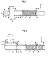
- Figur 2
- eine schematische Seitenansicht des vorderen, der Gleisschiene zugewandten Teils der Gleissicherungseinrichtung;
- Figur 3
- eine schematische Gesamtansicht der Gleissicherungseinrichtung in Seitenansicht;
Figur 4- eine schematische Teilansicht der Gleissicherungseinrichtung mit Schnellklemmschellen und daran befestigten Holmen; und
- Figur 5
- eine schematische Ansicht von möglichen Montageanordnungen der Holme an der Gleissicherungseinrichtung.
- Figure 1
- a schematic plan view of the front, the track rail facing part of the track protection device;
- Figure 2
- is a schematic side view of the front, the track rail facing part of the track protection device;
- Figure 3
- a schematic overall view of the track protection device in side view;
- Figure 4
- is a schematic partial view of the track protection device with quick clamps and spars attached; and
- Figure 5
- a schematic view of possible mounting arrangements of the spars on the track protection device.
Gemäß dem in den Figuren 1 bis 5 dargestellten Ausführungsbeispiel der Erfindung
ist eine Gleissicherungseinrichtung mit einem Haltebügel 1 zur Abstützung
einer Absperrung 2 für die Absicherung bzw. Abgrenzung eines (nicht näher dargestellten)
Streckenabschnittes einer Gleisschiene 3 mit einer Befestigungseinrichtung
4 zur lösbaren Festlegung des Haltebügels 1 an dem Profil der Gleisschiene
3 und einer in einem vorbestimmten Abstand zur Befestigungseinrichtung
4 verstellbaren sowie der Befestigungseinrichtung 4 gegenüber aus der Gleisstrecke
3 aufragenden Stütze 5 für die Absperrung 2 vorgesehen. Die Befestigungseinrichtung
4 der Gleissicherungseinrichtung 1 besitzt einen das im Querschnitt
im wesentlichen H- bzw. T-förmig ausgebildete Profil der Gleisschiene 3
zumindest bereichsweise übergreifenden Haltebereich 6, der entgegen der Federkraft
eines elastischen Federelementes 7 verschieblich und zur klemmenden
Festlegung der Befestigungseinrichtung 4 an das Profil der Gleisschiene 3 gelagert
ist. Die Befestigungseinrichtung 4 besitzt einen an dem der Gleisschiene 3
zugewandten Ende 8 der Gleissicherungseinrichtung 1 und zum Haltebereich 6
gegenüberliegend angeordneten starren Halteanschlag 9, der zur Festlegung der
Gleissicherungseinrichtung 1 an dem Profil der Gleisschiene 3 mit dem Haltebereich
6 zusammenwirkt und mit einem gleichfalls das H- bzw. T-förmige Profil der
Gleisschiene 3 zumindest bereichsweise umgreifenden Halteabschnitt 10 ausgestattet
ist. Der Haltebereich 6 besitzt einen im wesentlichen parallel zur Längserstreckung
der Gleisschiene 3 verlaufenden, im Querschnitt annähernd L-förmig
ausgebildeten längeren Winkelteil 11, dessen einer Schenkel 12 das Profil der
Gleisschiene 3 zumindest bereichsweise übergreift. Der starre Halteanschlag 9
weist einen parallel zur Längserstreckung der Gleisschiene 3 verlaufenden, im
Querschnitt annähernd L-förmig ausgebildeten, im Vergleich zum Winkelteil 11
des Haltebereiches 6 vorzugsweise kürzeren Anschlagteil 13 auf, dessen einer
Schenkel 14 gleichfalls das Profil der Gleisschiene 3 zumindest bereichsweise
übergreift. Der eine Schenkel 12 des Winkelteiles 11 und der eine Schenkel 14
des Anschlagteiles 13 sind gegensinnig geneigt und zueinander hin weisend an
den Rändern der Befestigungseinrichtung 4 angeordnet. Der Halteanschlag 9
weist ein im Querschnitt viereckig ausgebildetes Profilteil 15 auf, welches innerhalb
eines im Querschnitt entsprechend geformten Hohlprofilteiles 16 des Haltebereiches
6 koaxial ineinander längsverschieblich gelagert ist.According to the embodiment of the invention shown in Figures 1 to 5
is a track protection device with a bracket 1 for support
a barrier 2 for securing or delimiting a (not shown)
Section of a track rail 3 with a
Bei dem in der Zeichnung dargestellten Ausführungsbeispiel ist das elastische
Federelement 7 als Schraubendruckfeder 17 ausgebildet, die mit ihrer Windung
18 an einem am Profilteil 15 des starren Halteanschlages 9 und gegenüber dem
im Querschnitt annähernd L-förmig ausgebildeten Anschlagteil 13 beabstandeten
Stelle angebrachten Widerlager abgestützt ist. Vorzugsweise ist das Widerlager
durch ein zwischen die Windungen der Schraubendruckfeder 17 ragendes Anschlagorgan
19 ausgebildet, insbesondere in Form eines die Windungen der
Schraubendruckfeder durchsetzenden Zapfens. Diese Ausführung ermöglicht eine
kontinuierlich variable Anpassung der Verstellbreite der Befestigungseinrichtung
an unterschiedliche Gleisfußabmessungen auf einfachste Handhabung dadurch,
daß durch Verdrehen der Schraubenfeder entweder im Uhrzeigersinn oder entgegen
dem Uhrzeigersinn bis zum gewünschten Grad der wirksame Verstellweg der
Schraubendruckfeder entweder verkleinert oder vergrößert werden kann, ohne
daß es hierzu besonderer baulicher Veränderungen der Befestigungseinrichtung
unter Einsatz von Werkzeug bedarf. Nach der Figur 1 ist die Befestigungseinrichtung
auf kleinstmögliche Gleisfußabmessungen (von beispielsweise 125 mm) eingestellt;
demgemäß ist die Schraubenfeder mit ihrer endseitigen Windung 18' am
Zapfen 19 abgestützt und besitzt den maximal möglichen Verstellweg, während
nach Figur 2 die Schraubenfeder zur Einstellung auf größere Gleisfußabmessungen
(beispielsweise 150 mm) mit einer mittleren Windung 18 am Zapfen 19 abgestützt
ist.In the embodiment shown in the drawing, the
Zur einfacheren Einführung der Befestigungseinrichtung 4 der Gleissicherungseinrichtung
an die Unterseite 20 des Profils der auf Schotter oder Kies 21 verlaufenden
Gleisschiene 3 ist das der Gleisschiene 3 abgewandte und den längsverschieblich
gelagerten Haltebereich 6 überragende Ende des Profilteiles 15 des
starren Halteanschlages 9 mit einer Abknickung 22 versehen, deren Längsachse
gegenüber der Gleisebene unter einem Winkel von bis zu etwa 45° geneigt angeordnet
ist.For easier introduction of the
Femer ist das der Gleisschiene 3 abgewandte und den längsverschieblich gelagerten
Haltebereich 6 überragende Ende des Profilteiles 15 innerhalb eines Hohlprofilabschnittes
23 der Stütze 5 längsverschieblich geführt, wobei sowohl das innerhalb
des Hohlprofilabschnittes 23 gelagerte Profilteil 15 des Halteanschlages
9, als auch der Hohlprofilabschnitt 23 der Stütze 5 entsprechend mit einer Anzahl
von in bestimmten Abständen zueinander und quer zur Längserstreckung der
Profilteile angeordneter Bohrungen 24 versehen sein kann, vermittels derer und
eines die Bohrungen 24 durchgreifenden Sicherungsstiftes 25 der Abstand zwischen
der Stütze 5 und der Befestigungseinrichtung 4 variabel festlegbar ist.It is furthermore the one facing away from the track rail 3 and the one which is mounted to be longitudinally
Gemäß Figur 3 ist die Stütze 5 durch eine im wesentlichen die gesamte Nutzbreite
der Absperrung 2 übergreifenden und mit Schnellklemmschellen 26 zur Anbringung
der Absperrung ausgestatteten Haltestange 27 gebildet. Der Innendurchmesser
der Klemmschellen 26 entspricht dem äußeren Durchmesser der Holme
30, so daß ein fester Sitz der Holme 30 in der Klemmschelle 26 gewährleistet ist.
Durch die Öffnung 31 der Klemmschellen 26 werden die Holme bei der Montage
einfach in die Klemmschelle 26 eingeführt und sicher durch Schnappbefestigung
gehalten. Die gesamte Absperrung kann ohne den Einsatz von Werkzeugen oder
sonstiger Hilfsmittel von nur einer Person in kürzester Zeit montiert oder demontiert
werden. Da die Holme 30 gemäß der schematischen Darstellung nach Figur 4
in übergreifender Anordnung an der Gleissicherungseinrichtung befestigt werden,
sind Justierarbeiten aufgrund von vorhandenen Montagetoleranzen oder in ungleichmäßigen
Abständen am Gleis angebrachter Gleissicherungseinrichtung
nicht erforderlich. Figur 5 zeigt mehrere Möglichkeiten der Montageanordnungen
der befestigten Holme 30, wobei die mit der Bezugsziffer 30 a bezeichneten Holme
in der Farbe weiß, und die mit der Bezugsziffer 30 b bezeichneten Holme mit
der Farbe rot gekennzeichnet sind.According to FIG. 3, the support 5 is of essentially the entire useful width
the barrier 2 overlapping and with
Claims (3)
- Rail safety device having a barrier (2) for protecting and separating off a stretch of track rail (3), especially a stretch of railway track, a holding bracket (1), a fastening device (4) for releasably securing the holding bracket against the profile of the rail track (3), and a stanchion (5) for the barrier (2), which stanchion (5) is arranged at a predetermined spacing from the fastening device (4) beside the stretch of track, and the barrier having a plurality of at least nearly rigid bars (30) of predetermined lengths, which, for securing the bars (30) in position on the holding bracket (1), are releasably fastened by means of a quick closure mounting attached to the stanchion (1) of the holding bracket (1),
characterized in that
the quick closure mounting is in the form of a plurality of clamping clips (26), which have an opening (31), are attached to the stanchion of the holding bracket and the internal diameter fo which corresponds in that way to the external diameter of the bars (30), that a fastened fitting of the bars (30) in the clamping clip (26) on the one hand is secured, wherein the bars (30) when being mounted through the opening (31) in the clamping clip (26) are insertable and held securely by means of snap fastening, and on the other hand the bars (30) without employing tools or other aids can be demounted off the clamping clips (26). - Rail safety device according to claim 1, characterized in that the bars (30) have a length that exceeds the spacing between the two holding brackets (1) attached to the stretch of track in neighbouring positions.
- Rail safety device according to claim 1 or 2, characterized in that the bars (30) are made from an electrically insulating material, preferably a plastics material, and the bars (30) are arranged at the stretch of track in alternating colours so that a bar (30a) coloured in a predetermined first color, especially the colour white, is in each case followed by a bar (30b) provided with a different, second colour, especially the colour red.
Applications Claiming Priority (3)
| Application Number | Priority Date | Filing Date | Title |
|---|---|---|---|
| DE29515884U DE29515884U1 (en) | 1995-02-05 | 1995-10-10 | Track protection device |
| DE29515884U | 1995-10-10 | ||
| EP96116158A EP0768429B1 (en) | 1995-10-10 | 1996-10-09 | Railroad security fence |
Related Parent Applications (1)
| Application Number | Title | Priority Date | Filing Date |
|---|---|---|---|
| EP96116158A Division EP0768429B1 (en) | 1995-10-10 | 1996-10-09 | Railroad security fence |
Publications (2)
| Publication Number | Publication Date |
|---|---|
| EP0969148A1 EP0969148A1 (en) | 2000-01-05 |
| EP0969148B1 true EP0969148B1 (en) | 2003-09-17 |
Family
ID=26058277
Family Applications (1)
| Application Number | Title | Priority Date | Filing Date |
|---|---|---|---|
| EP99118760A Expired - Lifetime EP0969148B1 (en) | 1995-10-10 | 1996-10-09 | Railroad security fence |
Country Status (2)
| Country | Link |
|---|---|
| EP (1) | EP0969148B1 (en) |
| SI (1) | SI0768429T1 (en) |
Families Citing this family (3)
| Publication number | Priority date | Publication date | Assignee | Title |
|---|---|---|---|---|
| EP1149950A1 (en) * | 2000-04-27 | 2001-10-31 | DaimlerChrysler Rail Systems GmbH | Load bearing structure for a railway |
| DE202020103949U1 (en) | 2020-07-08 | 2021-10-11 | Arc Allround Cleaning Rheinfelden Ag | Track protection fence system |
| DE202020103948U1 (en) | 2020-07-08 | 2021-10-11 | Arc Allround Cleaning Rheinfelden Ag | Fastening element and fastening system for fastening a track attachment to a track system as well as a track protection fence system |
Family Cites Families (3)
| Publication number | Priority date | Publication date | Assignee | Title |
|---|---|---|---|---|
| AU5942473A (en) * | 1972-08-21 | 1975-02-20 | Woolcock R J | A fence |
| GB1572791A (en) * | 1976-12-23 | 1980-08-06 | Denecrown Ltd | Fencing |
| DE29501767U1 (en) * | 1995-02-05 | 1995-04-06 | Lademann Bewachungsschutz | Retaining bracket to support a barrier |
-
1996
- 1996-10-09 SI SI9630363T patent/SI0768429T1/en unknown
- 1996-10-09 EP EP99118760A patent/EP0969148B1/en not_active Expired - Lifetime
Also Published As
| Publication number | Publication date |
|---|---|
| SI0768429T1 (en) | 2002-10-31 |
| EP0969148A1 (en) | 2000-01-05 |
Similar Documents
| Publication | Publication Date | Title |
|---|---|---|
| DE19751625C2 (en) | Retaining bracket for supporting a barrier on a track rail | |
| EP0760880A1 (en) | Device for securing a frame on a layed rail section | |
| EP3241974B1 (en) | Assembly for a seal, in particular for a contact seal or for an automatically lowerable floor seal for doors | |
| DE3201100A1 (en) | MULTIPLE DISPLAY DEVICE | |
| EP0768429B1 (en) | Railroad security fence | |
| EP0969148B1 (en) | Railroad security fence | |
| DE69824076T2 (en) | Fixing system for panels, in particular panels for ventilated facades | |
| EP3428343B1 (en) | Screen for screening of accidents and foot therefor | |
| DE102006010447B4 (en) | Multifunctional kit for mounting storage devices | |
| DE19503638C1 (en) | Yoke holder for supporting block for railway track rail section | |
| DE19838604B4 (en) | Sign bridge for hanging traffic signs above the lanes of a traffic route | |
| EP1793058A2 (en) | Support for installations in the domestic and industrial field | |
| EP0778378B1 (en) | Security device for roof openings and method for manufacturing the security device | |
| DE4410535C1 (en) | Wood fastener | |
| CH688896A5 (en) | Fence, especially machine protection fence. | |
| DE4442551C2 (en) | Locking screw with a holding device | |
| DE2914078C2 (en) | Protective arrangement for systems to be crossed while electrical overhead lines are being pulled | |
| AT402645B (en) | HOLDING DEVICE FOR A PROTECTIVE FENCE HOLDING DEVICE FOR A PROTECTIVE FENCE | |
| DE4440430C1 (en) | Connector between wire mats | |
| EP3118054A1 (en) | Current rail suspension on beams | |
| DE1515385A1 (en) | Cable tray for the main supply lines of an electrical installation | |
| DE202023107164U1 (en) | Fence with vertical tensioning device | |
| DE7823557U1 (en) | BRACKET FOR FASTENING ROAD GUIDANCE POSTS TO GUIDANCE PLANK SUPPORT | |
| CH716168A2 (en) | System for attaching signaling elements. | |
| DE2950571A1 (en) | HANGING DEVICE FOR DOORS OR GATES |
Legal Events
| Date | Code | Title | Description |
|---|---|---|---|
| PUAI | Public reference made under article 153(3) epc to a published international application that has entered the european phase |
Free format text: ORIGINAL CODE: 0009012 |
|
| 17P | Request for examination filed |
Effective date: 19991005 |
|
| AC | Divisional application: reference to earlier application |
Ref document number: 768429 Country of ref document: EP |
|
| AK | Designated contracting states |
Kind code of ref document: A1 Designated state(s): AT BE CH DE DK ES FI FR GB GR IE IT LI LU MC NL PT SE |
|
| AX | Request for extension of the european patent |
Free format text: SI PAYMENT 19991005 |
|
| AKX | Designation fees paid |
Free format text: AT BE CH DE DK ES FI FR GB GR IE IT LI LU MC NL PT SE |
|
| AXX | Extension fees paid |
Free format text: SI PAYMENT 19991005 |
|
| 17Q | First examination report despatched |
Effective date: 20020826 |
|
| GRAH | Despatch of communication of intention to grant a patent |
Free format text: ORIGINAL CODE: EPIDOS IGRA |
|
| GRAS | Grant fee paid |
Free format text: ORIGINAL CODE: EPIDOSNIGR3 |
|
| GRAA | (expected) grant |
Free format text: ORIGINAL CODE: 0009210 |
|
| AC | Divisional application: reference to earlier application |
Ref document number: 0768429 Country of ref document: EP Kind code of ref document: P |
|
| AK | Designated contracting states |
Kind code of ref document: B1 Designated state(s): AT BE CH DE DK ES FI FR GB GR IE IT LI LU MC NL PT SE |
|
| AX | Request for extension of the european patent |
Extension state: SI |
|
| PG25 | Lapsed in a contracting state [announced via postgrant information from national office to epo] |
Ref country code: IE Free format text: LAPSE BECAUSE OF FAILURE TO SUBMIT A TRANSLATION OF THE DESCRIPTION OR TO PAY THE FEE WITHIN THE PRESCRIBED TIME-LIMIT Effective date: 20030917 Ref country code: FI Free format text: LAPSE BECAUSE OF FAILURE TO SUBMIT A TRANSLATION OF THE DESCRIPTION OR TO PAY THE FEE WITHIN THE PRESCRIBED TIME-LIMIT Effective date: 20030917 |
|
| REG | Reference to a national code |
Ref country code: GB Ref legal event code: FG4D Free format text: NOT ENGLISH |
|
| REG | Reference to a national code |
Ref country code: CH Ref legal event code: EP |
|
| PG25 | Lapsed in a contracting state [announced via postgrant information from national office to epo] |
Ref country code: LU Free format text: LAPSE BECAUSE OF NON-PAYMENT OF DUE FEES Effective date: 20031009 Ref country code: AT Free format text: LAPSE BECAUSE OF NON-PAYMENT OF DUE FEES Effective date: 20031009 |
|
| PG25 | Lapsed in a contracting state [announced via postgrant information from national office to epo] |
Ref country code: SE Free format text: LAPSE BECAUSE OF NON-PAYMENT OF DUE FEES Effective date: 20031010 |
|
| REF | Corresponds to: |
Ref document number: 59610722 Country of ref document: DE Date of ref document: 20031023 Kind code of ref document: P |
|
| REG | Reference to a national code |
Ref country code: IE Ref legal event code: FG4D Free format text: GERMAN |
|
| PG25 | Lapsed in a contracting state [announced via postgrant information from national office to epo] |
Ref country code: MC Free format text: LAPSE BECAUSE OF NON-PAYMENT OF DUE FEES Effective date: 20031031 |
|
| REG | Reference to a national code |
Ref country code: DK Ref legal event code: T3 |
|
| REG | Reference to a national code |
Ref country code: SE Ref legal event code: TRGR |
|
| PG25 | Lapsed in a contracting state [announced via postgrant information from national office to epo] |
Ref country code: GR Free format text: LAPSE BECAUSE OF FAILURE TO SUBMIT A TRANSLATION OF THE DESCRIPTION OR TO PAY THE FEE WITHIN THE PRESCRIBED TIME-LIMIT Effective date: 20031217 |
|
| PG25 | Lapsed in a contracting state [announced via postgrant information from national office to epo] |
Ref country code: PT Free format text: LAPSE BECAUSE OF FAILURE TO SUBMIT A TRANSLATION OF THE DESCRIPTION OR TO PAY THE FEE WITHIN THE PRESCRIBED TIME-LIMIT Effective date: 20031226 |
|
| GBT | Gb: translation of ep patent filed (gb section 77(6)(a)/1977) |
Effective date: 20031211 |
|
| REG | Reference to a national code |
Ref country code: IE Ref legal event code: FD4D |
|
| REG | Reference to a national code |
Ref country code: CH Ref legal event code: PL |
|
| REG | Reference to a national code |
Ref country code: ES Ref legal event code: FG2A Ref document number: 2209307 Country of ref document: ES Kind code of ref document: T3 |
|
| EUG | Se: european patent has lapsed | ||
| ET | Fr: translation filed | ||
| REG | Reference to a national code |
Ref country code: CH Ref legal event code: NV Representative=s name: ISLER & PEDRAZZINI AG Ref country code: CH Ref legal event code: AEN Free format text: DAS PATENT IST AUFGRUND DES WEITERBEHANDLUNGSANTRAGS VOM 09.06.2004 REAKTIVIERT WORDEN. |
|
| PLBE | No opposition filed within time limit |
Free format text: ORIGINAL CODE: 0009261 |
|
| STAA | Information on the status of an ep patent application or granted ep patent |
Free format text: STATUS: NO OPPOSITION FILED WITHIN TIME LIMIT |
|
| 26N | No opposition filed |
Effective date: 20040618 |
|
| PGFP | Annual fee paid to national office [announced via postgrant information from national office to epo] |
Ref country code: NL Payment date: 20050425 Year of fee payment: 9 Ref country code: FR Payment date: 20050425 Year of fee payment: 9 Ref country code: DK Payment date: 20050425 Year of fee payment: 9 |
|
| PGFP | Annual fee paid to national office [announced via postgrant information from national office to epo] |
Ref country code: ES Payment date: 20050426 Year of fee payment: 9 |
|
| PG25 | Lapsed in a contracting state [announced via postgrant information from national office to epo] |
Ref country code: IT Free format text: LAPSE BECAUSE OF NON-PAYMENT OF DUE FEES Effective date: 20051009 |
|
| PG25 | Lapsed in a contracting state [announced via postgrant information from national office to epo] |
Ref country code: ES Free format text: LAPSE BECAUSE OF NON-PAYMENT OF DUE FEES Effective date: 20051010 |
|
| PG25 | Lapsed in a contracting state [announced via postgrant information from national office to epo] |
Ref country code: DK Free format text: LAPSE BECAUSE OF NON-PAYMENT OF DUE FEES Effective date: 20051031 |
|
| PGFP | Annual fee paid to national office [announced via postgrant information from national office to epo] |
Ref country code: BE Payment date: 20051201 Year of fee payment: 10 |
|
| PGFP | Annual fee paid to national office [announced via postgrant information from national office to epo] |
Ref country code: CH Payment date: 20060426 Year of fee payment: 10 |
|
| PG25 | Lapsed in a contracting state [announced via postgrant information from national office to epo] |
Ref country code: NL Free format text: LAPSE BECAUSE OF NON-PAYMENT OF DUE FEES Effective date: 20060501 |
|
| REG | Reference to a national code |
Ref country code: DK Ref legal event code: EBP |
|
| PG25 | Lapsed in a contracting state [announced via postgrant information from national office to epo] |
Ref country code: FR Free format text: LAPSE BECAUSE OF NON-PAYMENT OF DUE FEES Effective date: 20060630 |
|
| NLV4 | Nl: lapsed or anulled due to non-payment of the annual fee |
Effective date: 20060501 |
|
| REG | Reference to a national code |
Ref country code: FR Ref legal event code: ST Effective date: 20060630 |
|
| PG25 | Lapsed in a contracting state [announced via postgrant information from national office to epo] |
Ref country code: LI Free format text: LAPSE BECAUSE OF NON-PAYMENT OF DUE FEES Effective date: 20061031 Ref country code: CH Free format text: LAPSE BECAUSE OF NON-PAYMENT OF DUE FEES Effective date: 20061031 |
|
| REG | Reference to a national code |
Ref country code: ES Ref legal event code: FD2A Effective date: 20051010 |
|
| REG | Reference to a national code |
Ref country code: CH Ref legal event code: PL |
|
| BERE | Be: lapsed |
Owner name: *MULLER HARALD Effective date: 20061031 |
|
| PG25 | Lapsed in a contracting state [announced via postgrant information from national office to epo] |
Ref country code: BE Free format text: LAPSE BECAUSE OF FAILURE TO SUBMIT A TRANSLATION OF THE DESCRIPTION OR TO PAY THE FEE WITHIN THE PRESCRIBED TIME-LIMIT Effective date: 20061031 |
|
| REG | Reference to a national code |
Ref country code: DE Ref legal event code: R081 Ref document number: 59610722 Country of ref document: DE Owner name: MUELLER, JENS, DE Free format text: FORMER OWNER: MUELLER, HARALD, DIPL.-ING., 45473 MUELHEIM, DE Effective date: 20110321 Ref country code: DE Ref legal event code: R081 Ref document number: 59610722 Country of ref document: DE Owner name: MUELLER, MARC OLIVER, DE Free format text: FORMER OWNER: MUELLER, HARALD, DIPL.-ING., 45473 MUELHEIM, DE Effective date: 20110321 |
|
| PGFP | Annual fee paid to national office [announced via postgrant information from national office to epo] |
Ref country code: GB Payment date: 20141022 Year of fee payment: 19 |
|
| PGFP | Annual fee paid to national office [announced via postgrant information from national office to epo] |
Ref country code: DE Payment date: 20151021 Year of fee payment: 20 |
|
| GBPC | Gb: european patent ceased through non-payment of renewal fee |
Effective date: 20151009 |
|
| PG25 | Lapsed in a contracting state [announced via postgrant information from national office to epo] |
Ref country code: GB Free format text: LAPSE BECAUSE OF NON-PAYMENT OF DUE FEES Effective date: 20151009 |
|
| REG | Reference to a national code |
Ref country code: DE Ref legal event code: R071 Ref document number: 59610722 Country of ref document: DE |