EP0969142A2 - Verfahren und Vorrichtung zur Durchmissung von Faserstoffsuspensionen - Google Patents
Verfahren und Vorrichtung zur Durchmissung von Faserstoffsuspensionen Download PDFInfo
- Publication number
- EP0969142A2 EP0969142A2 EP99112341A EP99112341A EP0969142A2 EP 0969142 A2 EP0969142 A2 EP 0969142A2 EP 99112341 A EP99112341 A EP 99112341A EP 99112341 A EP99112341 A EP 99112341A EP 0969142 A2 EP0969142 A2 EP 0969142A2
- Authority
- EP
- European Patent Office
- Prior art keywords
- suspension
- tube
- injection
- main flow
- stock
- Prior art date
- Legal status (The legal status is an assumption and is not a legal conclusion. Google has not performed a legal analysis and makes no representation as to the accuracy of the status listed.)
- Granted
Links
Images


Classifications
-
- D—TEXTILES; PAPER
- D21—PAPER-MAKING; PRODUCTION OF CELLULOSE
- D21F—PAPER-MAKING MACHINES; METHODS OF PRODUCING PAPER THEREON
- D21F1/00—Wet end of machines for making continuous webs of paper
- D21F1/08—Regulating consistency
-
- D—TEXTILES; PAPER
- D21—PAPER-MAKING; PRODUCTION OF CELLULOSE
- D21F—PAPER-MAKING MACHINES; METHODS OF PRODUCING PAPER THEREON
- D21F1/00—Wet end of machines for making continuous webs of paper
-
- D—TEXTILES; PAPER
- D21—PAPER-MAKING; PRODUCTION OF CELLULOSE
- D21F—PAPER-MAKING MACHINES; METHODS OF PRODUCING PAPER THEREON
- D21F1/00—Wet end of machines for making continuous webs of paper
- D21F1/66—Pulp catching, de-watering, or recovering; Re-use of pulp-water
Definitions
- the invention relates to a process and a device for mixing and piping suspensions of different natures and/or compositions in the stable section of a paper machine.
- a process and device for mixing suspensions is known from U.S. Patent No. 4,477,313 to Andersson, issued October 16, 1984. According to the Andersson patent, the backwater collected in the paper machine is passed into open backwater tanks, and is then fed back to the headbox via mixing pumps provided with a thick stock supply.
- an object of the invention is to provide a process for the mixing of suspensions of different nature and/or composition in the stable section of a paper machine, which provides an improvement in the quality as well as a reduction in production loss at the time of the changeover between types. It should be noted that in the context of the specification and claims, suspensions having different "characteristics" have differing natures and/or compositions.
- a further object of the invention is to provide a mixing device and/or piping in the stable section of a paper or cardboard machine for the blending of suspensions with higher solid content into a first suspension with little or no solid content, which likewise effects a reduction in quality losses and production loss at the time of the changeover between types.
- a "negligible" solid content means little or no solid content.
- a process for mixing suspensions having differing characteristics in the stable section of a paper machine includes piping of a first suspension in a mixing tube to form a main flow having a main flow direction in a longitudinal direction of the mixing tube, and injecting one or more additional suspensions into the mixing tube.
- the additional suspension(s) may have a different solid content than the first suspension.
- backwater indicates the total circulating backwater with which, along with the fresh stock, the concentration of the stock suspension required in the headbox is obtained, as depicted in Fig. 1.
- the cycles in the stable section are described in detail in the literature.
- a solid content of an additional suspension injected downstream along the main flow direction is, in each case, higher than or equal to a solid content of another additional suspension injected upstream along the main flow direction.
- the first suspension includes a suspension of a backwater of the paper machine, and an entire backwater volume stream flows through the mixing tube.
- the backwater volume stream may be reduced by a backwater substream sufficient, according to the dilution water principle, for weight basis control on a headbox of the paper machine.
- flow directions of each of the injected additional suspensions coincide with the main flow direction.
- Another embodiment of the process according to the invention includes maintaining a flow rate of the main flow in the mixing tube at a substantially constant level despite added liquid in the injected additional suspension, the flow rate of the main flow in the mixing tube increasing only in an end region of the mixing tube.
- the residence time of the backwater in the system should be as short as possible. Consequently, the flow rate in the mixing tube is optionally greater than 0.2 m/s, and further optionally, greater than 0.45 m/s (e.g., the dimensions of the mixing device are arranged to maintain these numerical flow rates).
- each additional suspension is injected concentrically in the main flow. If the recirculation from the headbox is not piped into the mixing tube, recirculation from a headbox may be passed via a line to a vertical separator second stage.
- the first suspension includes a backwater stream of the paper machine
- the injections of additional suspensions include, in order along the main flow, injection of recirculation from a headbox, followed by injection of accepted stock from a vertical separator second stage, followed by injection of recirculation of a first cleaner stage, followed by injection of accepted stock from a second cleaner stage, followed by injection of fresh stock.
- additional suspension streams may be injected between, before, or after the recited order, or the sequence may be adapted according to the concentration gradient in view of other conditions present, relative to the concentration of the suspension streams.
- the language "followed by” is not intended to preclude preceding, intervening, or following process operations after any individual injection, group of injections, or all the injections - other process operations may be placed in such positions without departing from the spirit of the invention.
- the first suspension includes a backwater stream of the paper machine
- the injections of the additional suspensions include, in order along the main flow, injection of accepted stock from a vertical separator second stage, followed by injection of recirculation from a first cleaner stage, followed by injection of accepted stock from a second cleaner stage, followed by injection of fresh stock.
- the first suspension includes a backwater stream of the paper machine
- the injections of the additional suspensions include, in order along the main flow, injection of accepted stock from a vertical separator second stage, followed by injection of accepted stock of a second cleaner stage, followed by injection of excess from a stock suspension feed to a headbox, followed by injection of fresh stock.
- the process further includes feeding a first backwater fraction of a backwater stream of the paper machine as the first suspension into a first mixing tube, and feeding a second backwater fraction of a backwater stream of the paper machine as the first suspension into a second mixing tube.
- the injections of the additional suspensions include, in order along the main flow, injection of accepted stock from a vertical separator second stage, followed by injection of accepted stock of a second cleaner stage, followed by injection of fresh stock.
- the injections of the additional suspensions include injection of accepted stock from a first cleaner stage.
- a return flow from the steamer may be passed via a feed line to a vertical separator second stage.
- Another advantageous embodiment of the process provides that the additional suspension(s) is added via a nozzle surrounded by the main flow.
- the flow rate vD in the nozzle and a flow rate vU of the main flow in a region surrounding the nozzle vU are in a ratio vD/vU from 3 to 15. Maintaining this relationship particularly favors a thorough mixing of the individual liquids.
- a region of mixing, i.e., in the region of the addition of the suspensions with higher solid content, between the first suspension and the additional suspension(s) is a hydraulically closed system, preventing equalization of pressure with the surrounding areas.
- the entire hydraulic system between the paper machine and the stock stream of the headbox can have a closed construction. In other words, there are no free surfaces of the suspension exposed to surrounding areas.
- a plurality of additional suspensions are injected into the main flow, and volume flow increases downstream along the main flow.
- the volume flow of the last injection added is smaller than the volume flow of the next to last injection added.
- the volume flow of the next to last injection added is greater than the volume flow of the last injection added.
- the injection of the additional suspension(s) includes wherein the injection of additional suspension(s) includes injection of a plurality of ingredients of fresh stock via a plurality of corresponding feeds in substantially the same location along the main flow.
- a mixing device for the blending of additional suspensions into a first suspension in the stable section of a paper machine includes a tube, and an intake in the tube for the first suspension, the first suspension having a negligible solid content.
- a plurality of feeds into the tube are provided for the additional suspensions to be blended with the first suspension into a blended suspension with a new solid content the additional suspensions having higher solid content than the first suspension.
- An outlet in the tube is provided for the blended suspension, the outlet being disposed downstream from a bend in the tube.
- a pump is connected to the tube downstream from the outlet, wherein an impeller axis of the pump is perpendicular to a plane containing portions of the tube both upstream and downstream of the bend.
- the mixing device is preferably arranged perpendicularly and has at its lower end a bend with a connection to the downstream pump (e.g., the cleaner pump).
- the plane of the bend and the perpendicular part of the mixing tube is perpendicular to the axis of rotation of the downstream pump. This ensures uniform inflow, in particular with double-suction pumps.
- a “mixing device” can include a mixing device and associated piping.
- each of the plurality of feeds includes an injection site that injects an additional suspension having a solid content equal to or greater than a previous injection site of a previous feed along the downstream direction of the main flow.
- concentration or the solid content of the suspensions added should increase continuously or remain the same in the direction of flow. The concentration differences at the individual mixing points are minimized, which ensures high mixing efficiency and low fluctuations in concentration.
- each of the injection sites may include an outlet port, with each outlet port pointing in a direction of the main flow. In this manner, the flow directions of the main flow and the added suspension(s) have essentially the same orientation.
- an internal diameter of the mixing device is designed such that a flow rate of the main flow is maintained at a substantially constant level despite added liquid in the additional suspensions blended therein, and such that the flow rate of the main flow in the mixing device increases only in an end region of the mixing device.
- Each of the plurality of feeds may include an injection site, and each injection site may terminate centrally in the mixing device.
- a recirculation line from a distributor of a headbox may pass via a line to a vertical separator second stage.
- a return flow line from a steamer of a headbox may be passed via a line to a vertical separator second stage.
- the feeds into the tube for the additional suspensions include, in order along the main flow, a feed for recirculation from a headbox, followed by a feed for accepted stock from a vertical separator second stage, followed by a feed for recirculation of a first cleaner stage, followed by a feed for accepted stock from a second cleaner stage, followed by a feed for fresh stock.
- additional feeds may be provided between, before, or after the recited order, or the sequence may be adapted according to the concentration gradient in view of other conditions present, relative to the concentration of the suspension streams.
- the language "followed by” is not intended to preclude preceding, intervening, or following structure after any individual feed, group of feeds, or all the feeds - other structure may be placed in such positions without departing from the spirit of the invention.
- the feeds into the tube for the additional suspensions include, in order along the main flow, a feed for accepted stock from a vertical separator second stage, followed by a feed for recirculation from a first cleaner stage, followed by a feed for accepted stock from a second cleaner stage, followed by a feed for fresh stock.
- a feed for accepted stock from a vertical separator second stage followed by a feed for recirculation from a first cleaner stage
- a feed for accepted stock from a second cleaner stage followed by a feed for fresh stock.
- the feeds into the tube for the additional suspensions include, in order along the main flow, a feed for accepted stock from a vertical separator second stage, followed by a feed for accepted stock of a second cleaner stage, followed by a feed for excess from a stock suspension feed to a headbox, followed by a feed for fresh stock.
- the tube includes a first mixing tube provided for a first backwater fraction of a backwater stream of the paper machine, and a second mixing tube for a second backwater fraction of a backwater steam of the paper machine.
- the feeds into the first mixing tube for the additional suspensions include, in order along the main flow, a feed for accepted stock from a vertical separator second stage, followed by a feed for accepted stock of a second cleaner stage, followed by a feed for fresh stock.
- the feeds into the second mixing tube for the additional suspensions include a feed for accepted stock from a first cleaner stage.
- each of the plurality of feeds includes an injection site surrounded by the main flow, and inside diameters of the injection sites and an inside diameter of the mixing device in the region of the injection site are arranged such that a flow rate vD in each injection site and a flow rate vU of the main flow in a region surrounding the injection site are in a ratio vD/vU from 3 to 15.
- a flow rate vD in each injection site and a flow rate vU of the main flow in a region surrounding the injection site are in a ratio vD/vU from 3 to 15.
- the mixing device is a hydraulically closed system excepting the intake and the outlet port for the blended suspension. That is, the mixing device is closed relative to its surroundings, or constitutes a closed hydraulic system having no pressure equalization capability with its surroundings. As noted above, the entire hydraulic system between the paper machine and the stock stream of the headbox can have a closed construction, and there are no free surfaces of the suspension exposed to surrounding areas.
- a mixing device for the blending of additional suspensions into a first suspension in the stable section of a paper machine includes a tube, and an intake in the tube for the first suspension, the first suspension having a negligible solid content.
- a plurality of feeds into the tube are provided for the additional suspensions to be blended with the first suspension into a blended suspension with a new solid content, the additional suspensions having higher solid content than the first suspension.
- An outlet in the tube is provided for the blended suspension, the outlet being disposed downstream from a bend in the tube.
- Each feed of the plurality of feeds injects an additional suspension having a solid content equal to or greater than a previous feed along the downstream direction of the main flow.
- a process for mixing suspensions having differing solid content in the stable section of a paper machine includes feeding a backwater suspension from a wet section of the paper machine as a main flow into a closed vertical mixing tube, then injecting accepted stock from a vertical separator system concentrically into the main flow to form a blended suspension in the mixing tube, the injection of the accepted stock having a higher solid content than the backwater suspension and a higher flow rate than the main flow.
- Fresh stock is then injected concentrically into the blended suspension in the mixing tube, the injection of the fresh stock having a higher solid content than the blended suspension and a higher flow rate than the blended suspension, then the blended suspension is pumped from the mixing tube.
- a flow rate in the mixing tube may be maintained at a substantially constant level upstream and downstream of the injections.
- a mixing device for the blending of additional suspensions into a backwater suspension in the stable section of a paper machine includes a closed vertical mixing tube having a bend at a lower end thereof.
- An intake is provided at a top of the tube for a backwater suspension from a wet section of the paper machine, the backwater suspension forming a main flow.
- a first concentric nozzle injects accepted stock, having a higher solid content than the backwater suspension, from a vertical separator system into the mixing tube to form a blended suspension.
- the first concentric nozzle is concentric to the mixing tube and upstream of the bend, and injects the accepted stock at a higher flow rate than the main flow.
- a second concentric nozzle injects fresh stock having a higher solid content than the blended suspension into the mixing tube.
- the second concentric nozzle is concentric to the mixing tube and downstream of the bend, and injects the fresh stock at a higher flow rate than the blended suspension.
- An outlet in the tube is disposed downstream from the bend and from the second concentric nozzle.
- a diameter of the mixing tube may increase in the direction of the main flow to maintain a flow rate in the mixing tube at a substantially constant level upstream and downstream of both of the first concentric nozzle and the second concentric nozzle.
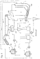
- Fig. 1 depicts a schematic detail of a known paper machine with the stable section and the beginning of the wet section of the paper machine including the headbox on a Fourdrinier paper machine.
- a "paper machine” is inclusive of at least paper and cardboard machines.
- a stock suspension is fed to a headbox 1 via a line 100, distributed in the headbox over the width of the machine, and applied to a wire 2.
- the backwater penetrating the wire 2 is fed via lines 102 into an open backwater tank 4.
- a mixing tube 5 is provided near the backwater tank 4, and the overflow of a deaeration tank 14 is fed as the main flow via the line 104 into the mixing tube 5.
- the overflow of a distribution pipe of the headbox 1 is injected, via a line 101, into the mixing tube 5.
- Accepted stock from a vertical separator second stage 9 is fed into the mixing tube 5 via the line 103.
- the mixing tube 5 is introduced into the output of the (open) backwater tank 4.
- a further addition of fresh stock is made via the line 105 after the bend in the mixing tube 105.
- a first cleaner pump 11 delivers the stock suspension from the mixing tube 5 via the line 106 to a first cleaner stage 6. From the first cleaner stage 6, the stock suspension arrives, via a mixing tank 16 and conveyed by a second cleaner pump 12, to a second cleaner stage 7. The stock suspension is pumped via a line 107 to the deaeration tank 14. The deaeration tank 14 is connected to a suction line 108 to degas the stock suspension.
- stock suspension from the first cleaner stage 6 is also fed into the deaeration tank 14 via a line 109.
- the stock suspension arrives via a line 110, and conveyed by a headbox pump 10, to a vertical separator first stage 8.
- the stock suspension flows from the vertical separator first stage 8, via a line 100, to the distribution pipe of the headbox 1.
- a coarser fraction of the vertical separator first stage 8 is again fed via an open-tank intermediate station 15 and line 111, to the vertical separator second stage 9, in which separation again takes place. In this manner, the finer fraction is passed back via the line 103 (as noted above) into the mixing tube 5, while the coarse fraction is discharged from the vertical separator second stage 9.
- Fig. 2 depicts, in schematic detail, the invention as applied to the stable section of a paper machine.
- Fig. 2 also shows the beginning of the wet section of a paper machine, including a headbox 1.
- a Fourdrinier paper machine is depicted here; however, the invention can also be used on hybrid formers and gap formers. It should be noted that where a description of an element is omitted hereinafter, the structure and function of such elements substantially correspond to those described with reference to Fig. 1.
- Fig. 2 shows how stock suspension is fed via the line 100 to the headbox 1.
- the headbox 1 delivers the stock suspension onto a wire 2 of the wet section 3, with a first backwater fraction collected and transported away via a line 102, and a second backwater fraction collected and transported away via a line 102.1.
- the first backwater fraction is split at two junctions or connecting branches, and is thereby distributed via the line 102 to a mixing tube 5, and also to two hydraulic mixers 15.1 and 16.1.
- the first backwater fraction collected and transported via line 102 has, in general, the least solid content, and is therefore introduced as a first suspension into the mixing tube 5.
- the second backwater fraction is fed to the mixing tube 5 from the other side of the mixing tube 5 and downstream from the first backwater fraction.
- a recirculation stream coming out of the distributor of the headbox 1 is introduced via a line 101 into the backwater stream of the second backwater fraction.
- a stock suspension from the vertical separator second stage 9 is introduced via the line 103.
- the accepted stock of the first cleaner stage 6 is fed via the line 109 directly to the deaeration tank 14, and the accepted stock from the second cleaner stage is also fed, via the line 107, into the deaeration tank 14.
- the excess from the deaeration tank 14 is introduced from the deaeration tank 14 into the mixing tube 5 via the line 104, in this embodiment downstream of the line 103. It should be noted that it is possible to add additional accepted stocks from additional cleaner stages, although such is not explicitly depicted in Fig. 2.
- each feed line e.g., 102, 102.1, 101, 103, and 104
- each feed line is disposed such that, in each case, an equally concentrated or more concentrated stock suspension flow is introduced into a less concentrated stock suspension flow.
- the sequence of introduction of the feeds may be changed, such that this condition for the concentrations of the stock suspension added remains the same, i.e., equally concentrated or more concentrated stock suspension flows are introduced into a less concentrated stock suspension flow.
- FIG. 2 Another advantageous characteristic of the process diagram depicted in Fig. 2 consists in the closed hydraulic cycle, i.e., the elimination of the open storage tanks 15 and 16 depicted in Fig. 1.
- the open tanks 15 and 16, according to the invention, are replaced with closed hydraulic mixers 15.1 and 16.1.
- a portion of the first backwater fraction is fed via the line 102 to the line 112.2. This portion of the first backwater fraction is then mixed in the hydraulic mixer 16.1 with the excess of the suspension from the first cleaner stage 6.
- the suspension is fed from the hydraulic mixer 16.1 via a pump 12 to the second cleaner stage 7.
- the accepted stock of the second cleaner stage 7, as noted above, is passed via the line 107 into the deaeration tank 14.
- the second hydraulic mixer 15.1 is also fed, via the line 112.1, with a portion of the first backwater fraction from the line 102.
- the coarse fraction of the vertical separator first stage 8 is fed into the hydraulic mixer 15.1 via the line 111.
- the second hydraulic mixer can mix accepted stock passed from a vertical separator third stage 9.1 via the line 113, but it is not necessary that the vertical separator third stage 9.1 be used.
- the arrangement of the vertical separator third stage 9.1 although shown only in Fig. 2a, may be similarly applied in Figs. 2, 2b, and 2c.
- the mixed suspension from the second hydraulic mixer is passed by means of the pump 13 to the vertical separator second stage 9.
- the accepted stock of the vertical separator second stage is, in turn, fed via the line 103 to the mixing tube 5.
- the stock suspension is delivered from the deaeration tank 14 via the line 110 by means of the headbox pump 10 to the vertical separator first stage 8.
- the accepted stock of the vertical separator first stage is fed via the line 100 to the distributor of the headbox 1.
- the deaeration tank 14 has a suction line 108 that deaerates the stock suspension therein.
- the feeds into the tube 5 for the additional suspensions include, in order along the main flow, as feed 101 for recirculation from a headbox 1, a feed 103 for accepted stock from a vertical separator second stage 9, followed by a feed 109 for recirculation from a first cleaner stage 106, followed by a feed 107 for accepted stock from a second cleaner stage 7 (these two combined in the recited order in the deaeration tank 14, from which a feed 104 extends to the tube 5), followed by a feed 105 for fresh stock.
- circulation of the backwater is significantly reduced, and a more rapid adaptation at the time of a type changeover is enabled. Accordingly, the amount of defective production is significantly reduced at the time of the type changeover, and fewer quality losses result.
- the first suspension includes a suspension of a backwater of the paper machine, and an entire backwater volume stream flows through the mixing tube 5.
- the backwater volume stream is reduced by a backwater substream sufficient, according to the dilution water principle, for weight basis control on the headbox 1 of the paper machine.
- the dilution water principle as applied in a headbox is well known to one of skill in the art, and a description thereof is found in U.S. Patent No. 5,707,495 to Heinzmann et al., the disclosure of which is expressly incorporated by reference herein in its entirety.
- FIG. 2a A first variant of the suspension piping of the stable section of the paper machine, according to the embodiment of the invention of Fig. 2, is depicted in Fig. 2a.
- the recirculation from the headbox 1 is not passed into the mixing tube 5, but is passed via the line 101 into the pipe 112.1 directly upstream from the second hydraulic mixer 15.1.
- the headbox 1 includes a steamer 29, a return flow of which is also introduced via the return line 114 into the pipe 112.1 immediately upstream from the second hydraulic mixer 15.1.
- the remaining suspension piping and elements of the mixing device correspond to those described with reference to Fig. 2 and depicted therein.
- the recirculation line 101 from a distributor of the headbox 1 may be passed to the vertical separator second stage 9 (via the second hydraulic mixer 15.1).
- the return flow line 114 from a steamer 29 of the headbox 1 may be passed to the vertical separator second stage 9 (also via the second hydraulic mixer 15.1).
- the feeds into the tube 5 for the additional suspensions include, in order along the main flow, a feed 103 for accepted stock from a vertical separator second stage 9, followed by a feed 109 for recirculation from a first cleaner stage 106, followed by a feed 107 for accepted stock from a second cleaner stage 7 (these two combined in the recited order in the deaeration tank 14, from which a feed 104 extends to the tube 5), followed by a feed 105 for fresh stock.
- a feed 103 for accepted stock from a vertical separator second stage 9 followed by a feed 109 for recirculation from a first cleaner stage 106, followed by a feed 107 for accepted stock from a second cleaner stage 7 (these two combined in the recited order in the deaeration tank 14, from which a feed 104 extends to the tube 5), followed by a feed 105 for fresh stock.
- An advantageous effect of this first variant of the suspension piping is that possible pressure fluctuations and pulsations that are passed through the headbox 1 or that develop in the headbox 1 can be directed to a noncritical region of the stable section and can be compensated in the noncritical region.
- the pulsation-sensitive regions of the stable section e.g., including the mixing tube 5 and the feed lines 106, 109, 110, and 100, are protected from pressure fluctuations and pulsations.
- Fig. 2b depicts a second variant of the embodiment of Fig. 2 according to the invention of the suspension piping in the stable section of a paper machine.
- the variant depicted in Fig. 2b is essentially similar to that of Fig. 2, except that the deaeration tank 14 is omitted.
- a portion of the first backwater fraction is discharged via the line 102 and passed to the mixing tube 5, while another portion of the first backwater fraction is fed (via lines 102.3, 112.1, and 112.2) to two hydraulic mixers 15.1 and 16.1.
- the first backwater fraction is introduced into the mixing tube 5 as the first fraction since it contains the smallest proportion of solid content.
- the second backwater fraction discharged via line 102.1 which has a somewhat higher concentration (e.g., solid content), is fed to the mixing tube 5 from the other side of the mixing tube 5 and downstream from the addition of the first backwater fraction.
- the accepted stock of the vertical separator second stage 9 which again has a somewhat higher concentration, is introduced via the line 103.
- An overflow of the second cleaner stage 7 is then introduced via the line 107, followed by the addition of a control return flow from a stock suspension addition to the headbox 1 via a pressure relief line 115.
- a branch provided in the line 100 leads to pressure relief line 115 back to the mixing tube 5.
- the pressure relief line 115 is valve-controlled via a valve 30.
- the control of the valve 30 is performed according to a pressure measurement on the headbox 1.
- the pressure measurement is taken via measurement lines 121 and 122, and a control system (PIC - Pressure Indicated Control) 40 controls the valve 30.
- the control of the valve 30 is performed such that in the case of excess pressure in the headbox 1, the valve 30 in the line 115 is opened, and pressure relief of the stock addition to the headbox 1 is achieved by return flow via the line 115.
- the necessary pressure sensor for the measurement of the pressure in the headbox 1 may be disposed in the intake region of the stock suspension, in the region of the steamer 29, or in the region of a turbulence insert in the headbox 1.
- the headbox includes the steamer 29, with a return flow line 114 extending to the line 112.1, upstream of the second hydraulic mixer 15.1, as described with reference to Fig. 2a.
- the steamer 29, as well as the return flow line 114 may be omitted with appropriate design and control of the pressure relief line 115.
- the second portion of the first backwater fraction, which is discharged via the line 102, is again subdivided, as with the embodiments in Figs. 2 and 2a, into the lines 112.1 and 112.2.
- the line 112.1 leads to the second hydraulic mixer 15.1 as previously described with reference to Fig. 2a. Any return flow from the headbox steamer 29 in line 114 is fed into line 112.1 upstream from the second hydraulic mixer 15.1. Recirculation from the headbox 1 is also fed into line 112.1 via the line 101.
- the mixture of these three stock suspensions (or, e.g., two stock suspensions if no return flow from the steamer 29 is present) is added to the second hydraulic mixer 15.1.
- a pump 13 at the output of the second hydraulic mixer 15.1 delivers the stock suspension to the vertical separator second stage 9.
- the accepted stock of the vertical separator second stage 9 is again added to the mixing tube 5 via the line 103.
- backwater of the first fraction is also piped, via line 112.2, to the first hydraulic mixer 16.1.
- the second fraction from the first cleaner stage 6 is fed in to the first hydraulic mixer 16.1 via the line 116 and is mixed therein with the backwater of the first fraction.
- the resultant suspension mixture is delivered from the hydraulic mixing tube 16.1, via a second cleaner pump 12, to the second cleaner stage 7.
- the accepted stock from the second cleaner stage 7 is added via the line 107 to the mixing tube 5.
- the remaining suspension piping and elements of the mixing device correspond to those described with reference to Fig. 2 and 2a and depicted therein.
- the feeds into the tube 5 for the additional suspensions include, in order along the main flow, a feed 103 for accepted stock from a vertical separator second stage 9, followed by a feed 107 for accepted stock of a second cleaner stage 7, followed by a feed 115 for excess from a stock suspension feed 100 to a headbox 1, followed by a feed 105 for fresh stock.
- a branch of the line 109 from the first cleaner stage 6 leads into a line 117.
- the line 117 takes excess accepted stock from the first cleaner stage 6 to the mixing tube 5, and a controlled valve 31 (HIC - Hand Indicated Control) controls the line 117.
- HIC - Hand Indicated Control controls the line 117.
- Fig. 2c depicts a third variant of the embodiment stock suspension piping with a mixing tube in the stable section of a paper machine, again, without a deaeration tank as in Fig. 2b.
- two mixing tubes 5 and 5.1 are employed.
- Fig. 2c similarly to Fig. 2b, the first backwater fraction of the drainage device 3 of the backwater section is discharged and then divided via the lines 102.2 and 102.3. A portion of the first backwater fraction is fed as a main flow, via the line 102.2, to a first mixing tube 5.
- the accepted stock from the vertical separator second stage 9 is introduced into the first mixing tube 5 downstream of the main flow via the line 103.
- overflow from the second cleaner stage 7 enters the first mixing tube 5 via the line 107 downstream of line 103.
- accepted stock having a concentration (e.g., solid content) higher than that of the suspension mixture into which it is introduced, is mixed via a feed line 105 arranged near to the output of the first mixing tube 5. Accordingly, the accepted stock introduced via the feed line 105 is mixed with the suspension mixture in the mixing tube 5. The entire suspension mixture leaving the first mixing tube 5 is fed via a first cleaner pump 11 to the first cleaner stage 6.
- the second part of the first backwater fraction which is fed via the lines 102 and 102.3 to a branch and thereby to lines 112.1 and 112.2, arrives via line 112.2 to the first hydraulic mixer 16.1 and via line 112.1 to the second hydraulic mixer 15.1.
- overflow from the steamer 29 of the headbox 1 is fed via the line 114, and the recirculation from the headbox is fed via the line 101.
- the coarse fraction of the vertical separator first stage 8 is added to the second hydraulic mixer 15.1 via the line 111.
- the accepted stock of a vertical separator third stage 9.1 (as shown in Fig.
- the remaining stock from the first cleaner stage 6 is added, via the line 116, to the first hydraulic mixer 16.1, as is a portion of the first backwater fraction via the line 112.2. From the first hydraulic mixer 16.1, the mixture is delivered to the second cleaner stage 7 by the second cleaner pump 12. As noted above, overflow from the second cleaner stage 7 is added via the line 107 to the mixing tube 5, where the second cleaner stage 7 overflow is added to the main flow stream including the accepted stock from the vertical separator second stage 9.
- the second backwater fraction of the drainage device 3 is fed via the line 102.1 to a second mixing tube 5.1, into which the overflow of the first cleaner stage 6 is then blended via the line 109.
- This entire suspension is delivered by another pump 17 from the second mixing tube 5.1, via a line 118, to the vertical separator first stage 8.
- a feed line 100 leads from the vertical separator first stage 8 to the headbox 1 and delivers the fresh stock suspension to the headbox 1.
- the remaining suspension piping and elements of the mixing device correspond to those described with reference to Fig. 2 and depicted therein.
- the "mixing tube 5" includes a first mixing tube 5 provided for a first backwater fraction of a backwater stream of the paper machine, and a second mixing tube 5.1 for a second backwater fraction of a backwater stream of the paper machine.
- the feeds (or injections) into the first mixing tube 5 for the additional suspensions include, in order along the main flow, a feed 103 for accepted stock from a vertical separator second stage 9, followed by a feed 107 for accepted stock of a second cleaner stage 7, followed by a feed 105 for fresh stock.
- the feeds into the second mixing tube 5.1 for the additional suspensions include a feed 109 for accepted stock from a first cleaner stage 6.
- the second mixing tube 5.1 serves for subsequent dilution of the second backwater fraction, and the recirculation volume of the entire system is reduced. Moreover, an improvement of the stability of the operation is achieved, without the risk of back flows complications, which result in inadmissibly high stock concentrations and can negatively affect the longitudinal profile of the paper produced. Moreover, the cleaner capacity can also be reduced, whereby a further reduction of the circulating volume is established.
- Fig. 3 depicts, in detail, an example of a mixing tube 5 according to the invention, with corresponding injections.
- the mixing tube 5 from Fig. 3 is depicted by way of example, and is not identical to the mixing tubes 5, 5.1 of the preceding drawings, since the individual examples shown differ in the concentration relationships of the suspension added.
- the mixing tube of Fig. 3 employs injections as shown in various of the previous drawings, and the overall structure of each mixing tube 5, 5.1 and injections thereof of the embodiments of the invention are preferably structured in a manner corresponding to the structure depicted in Fig. 3 and as described below.
- the first fraction of the backwater from the wet section is added via the line 102 to the mixing tube 5 through an intake port 20.
- the second fraction of the backwater is fed to a port 21 via the line 102.1.
- the recirculation of the stock suspension from the distribution pipe of the headbox 1 is added to the second fraction of the backwater via a line 101 and a nozzle 22.
- the mixture of the second fraction of the backwater with the recirculation from the headbox 1 are then injected together through a nozzle 23 into the first fraction of the backwater in the mixing tube 5 and thoroughly mixed.
- nozzle 24 Downstream from the nozzle 23, another nozzle 24 is depicted in which the accepted stock of the vertical separator second stage 9 is added to the mixing tube 5 via the line 103, and injected into the suspension stream.
- the recirculation of the first cleaner stage 6 is then added via the line 109 and a nozzle 25.
- the mixing tube 5 is then bent by substantially 90 degrees.
- two concentrically arranged nozzles 26,27 are installed.
- the first nozzle 26 adds the accepted stock from the second cleaner stage 7 via the line 107.
- volume flow increases downstream along the main flow, and the volume flow of the last injection added via nozzle 27 is smaller than the volume flow of the next to last injection added via nozzle 26 (the volume flow of the next to last injection added via nozzle 26 is greater than the volume flow of the last injection added via nozzle 27).
- the finished stock suspension leaves the mixing tube 5 through the outlet port 28, and is delivered via the line 106 to the first cleaner pump 11 and the first cleaner stage 6.
- inside diameters of the nozzles 22, 23, 24, 25, 26, 27, and 32 and an inside diameter of the mixing tube 5 in the region of the respective nozzles are arranged such that a flow rate vD in each respective nozzle and a flow rate vU of the main flow in a region surrounding the respective nozzle are in a ratio vD/vU from 3 to 15. Maintaining this relationship particularly favors a thorough mixing of the individual liquids.
- the mixing tube 5 is a hydraulically closed system excepting the intake ports 20, 21, and the outlet port 28 for the blended suspension. That is, the mixing tube 5 is closed relative to its surroundings, or constitutes a closed hydraulic system having no pressure equalization capability with its surroundings. Moreover, the entire hydraulic system of Figs. 2-2c between the paper machine and the stock stream of the headbox can have a closed construction, and there are no free surfaces of the suspension exposed to surrounding areas.
- internal diameters of the mixing device (tube) 5 is designed such that a flow rate of the main flow is maintained at a substantially constant level despite added liquid in the additional suspensions blended therein, and such that the flow rate of the main flow in the mixing device 5 increases only in an end region of the mixing device.
- each of the plurality of feeds includes an injection site that injects an additional suspension having a solid content equal to or greater than a previous injection site of a previous feed along the downstream direction of the main flow.
- concentration or the solid content of the suspensions added should increase continuously or remain the same in the direction of flow. The concentration differences at the individual mixing points are minimized, which ensures high mixing efficiency and low fluctuations in concentration.
- each of the injection sites may include an outlet port or nozzle, with each outlet port pointing in a direction of the main flow. In this manner, the flow directions of the main flow and the added suspension(s) have essentially the same orientation.
- a mixing device 5 for the blending of additional suspensions into a first suspension in the stable section of a paper machine includes a tube 5, and an intake 20 and/or 21 in the tube for the first suspension, the first suspension having a negligible solid content.
- a plurality of feeds 101, 103, 109, 117, 105, 107 into the tube 5 are provided for the additional suspensions to be blended with the first suspension into a blended suspension with a new solid content, the additional suspensions having higher solid content than the first suspension.
- An outlet 28 in the tube 5 is provided for the blended suspension, the outlet being disposed downstream from a bend in the tube.
- a pump 11 is connected to the tube 5 downstream from the outlet 28, wherein an impeller axis 11a of the pump 11 is perpendicular to a plane containing portions of the tube 5 both upstream and downstream of the bend. That is, the mixing device 5 is preferably arranged perpendicularly and has at its lower end a bend with a connection to the downstream pump (e.g., the cleaner pump 11). The plane of the bend and the perpendicular part of the mixing tube 5 is perpendicular to the axis 11a of rotation of the downstream pump 11. This ensures uniform inflow, in particular with double-suction pumps.
- the flow rate in the mixing tube 5 is optionally greater than 0.2 m/s, and further optionally, greater than 0.45 m/s (e.g., the dimensions of the mixing device 5 are arranged to maintain these numerical flow rates).
- an additional nozzle 32 adds accepted stock of the first cleaner stage 6 via a line 117 downstream from the injection through the nozzle 25.
- Fresh stock is conventionally formed from several components or ingredients, and in the mixing tube 5 of Fig. 3, the fresh stock is premixed from the several components or ingredients and injected into the main flow of the mixing tube 5 via the line 105 and the nozzle 27.
- Fig. 4 is a detailed view of a modification of the feed 105 and nozzle 27 as employed in the mixing tube 5 of Fig. 3.
- different components or ingredients of fresh stock are not premixed, but are added to the mixing tube via separate feeds 105, 105a, 105b at the same location as feed 103 of Fig. 3. That is, in the modification depicted in Fig. 4, each different component or ingredient is provided with a line and nozzle.
- a first component or ingredient of the fresh stock is injected into the main flow of the tube 5 via line 105 and nozzle 27, a second component or ingredient of the fresh stock is injected into the main flow of the tube 5 via feed 105a and nozzle 27a, and a third component or ingredient of the fresh stock is injected into the main flow of the tube 5 via feed 105b and nozzle 27b.
- the various components or ingredients of fresh stock are injected into the main flow of the mixing tube via individual feeds 105, 105a, 105b, each with an individual nozzle 27, 27a, 27b for each of the feeds (lines) and for each component or ingredient. More than three ingredients components may be so injected.
- a plurality of ingredients of fresh stock are injected via a plurality of corresponding feeds 105, 105a, 105b (etc.) in substantially the same location along said main flow.
- the process includes feeding a backwater suspension from a wet section of the paper machine as a main flow into a closed vertical mixing tube 5, then injecting accepted stock (e.g., via feed 103) from a vertical separator system (e.g., 8; 9) concentrically into the main flow to form a blended suspension in the mixing tube 5, the injection of the accepted stock having a higher solid content than the backwater suspension and a higher flow rate than the main flow.
- Fresh stock is then injected concentrically (e.g., via feed 105) into the blended suspension in the mixing tube 5, the injection of the fresh stock having a higher solid content than the blended suspension and a higher flow rate than the blended suspension, then the blended suspension is pumped from the mixing tube 5.
- a flow rate in the mixing tube may be maintained at a substantially constant level upstream and downstream of the injections.
- the process for the mixing of suspension of different natures and/or compositions in the stable section of a paper or cardboard machine provides an improvement of quality and a reduction of production losses at the time of a type changeover.
- larger backwater tanks are avoided, thereby reducing the amount of water in circulation in the paper machine, and, thus, at the time of the type changeover in the paper machine, a more rapid change in the composition of the stock suspensions is possible. Based on this more rapid change, the quality losses, and therefore also the production losses, are reduced.
- the "backwater” indicates the total circulating backwater with which, along with the fresh stock, the concentration of the stock suspension required in the headbox is obtained, as depicted in Fig. 1. The cycles in the stable section are described in detail in the literature.
- a mixing device includes a closed vertical mixing tube 5 having a bend at a lower end thereof.
- An intake 20 and/or 21 is provided at a top of the tube for a backwater suspension from a wet section of the paper machine, the backwater suspension forming a main flow.
- a first concentric nozzle e.g., nozzle 24 connected to feed 103 injects accepted stock, having a higher solid content than the backwater suspension, from a vertical separator system (e.g., 8; 9) into the mixing tube 5 to form a blended suspension.
- the first concentric nozzle 24 is concentric to the mixing tube 5 and upstream of the bend, and injects the accepted stock at a higher flow rate than the main flow.
- a second concentric nozzle (e.g., nozzle 27 connected to feed 105) injects fresh stock having a higher solid content than the blended suspension into the mixing tube 5.
- the second concentric nozzle 27 is concentric to the mixing tube 5 and downstream of the bend, and injects the fresh stock at a higher flow rate than the blended suspension.
- An outlet 28 in the tube 5 is disposed downstream from the bend and from the second concentric nozzle 27.
- a diameter of the mixing tube 5 may increase in the direction of the main flow to maintain a flow rate in the mixing tube 5 at a substantially constant level upstream and downstream of both of the first concentric nozzle 24 and the second concentric nozzle 27.
- the mixing device as described enables an effective and economical blending of suspensions with a higher solid content into a first suspension with little or no solid content in the stable section of a paper or cardboard machine, while omitting an expensive backwater tank. At the same time, the mixing device reduces the amount of water circulated as well as quality losses and production loss at the time of a type changeover.
Landscapes
- Paper (AREA)
Applications Claiming Priority (4)
| Application Number | Priority Date | Filing Date | Title |
|---|---|---|---|
| DE19828998 | 1998-06-29 | ||
| DE19828998 | 1998-06-29 | ||
| DE19859770 | 1998-12-23 | ||
| DE19859770A DE19859770A1 (de) | 1998-06-29 | 1998-12-23 | Verfahren und Vorrichtung zum Mischen von Sroffsuspension |
Publications (3)
| Publication Number | Publication Date |
|---|---|
| EP0969142A2 true EP0969142A2 (de) | 2000-01-05 |
| EP0969142A3 EP0969142A3 (de) | 2000-06-14 |
| EP0969142B1 EP0969142B1 (de) | 2004-03-24 |
Family
ID=26047108
Family Applications (1)
| Application Number | Title | Priority Date | Filing Date |
|---|---|---|---|
| EP99112341A Expired - Lifetime EP0969142B1 (de) | 1998-06-29 | 1999-06-28 | Verfahren und Vorrichtung zur Durchmissung von Faserstoffsuspensionen |
Country Status (3)
| Country | Link |
|---|---|
| US (2) | US6200417B1 (de) |
| EP (1) | EP0969142B1 (de) |
| AT (1) | ATE262611T1 (de) |
Cited By (5)
| Publication number | Priority date | Publication date | Assignee | Title |
|---|---|---|---|---|
| EP1126077A2 (de) * | 2000-02-09 | 2001-08-22 | Voith Paper Patent GmbH | Verfahren und Vorrichtung zur Stoffaufbereitung |
| DE102006036018B3 (de) * | 2006-08-02 | 2008-01-31 | Voith Patent Gmbh | Verfahren zur Zuführung einer Faserstoffsuspension zu einem Stoffauflauf einer Papiermaschine |
| DE102009054816A1 (de) | 2009-12-17 | 2011-06-22 | Voith Patent GmbH, 89522 | Konstantteil |
| WO2014012814A1 (de) * | 2012-07-18 | 2014-01-23 | Voith Patent Gmbh | Sicherheitspapier-konstantteil |
| EP2690216A1 (de) | 2012-07-25 | 2014-01-29 | Toscotec S.P.A. | System zur Herstellung einer Zellulosebahn aus einer wässrigen Suspension von Zellulosefasern |
Families Citing this family (13)
| Publication number | Priority date | Publication date | Assignee | Title |
|---|---|---|---|---|
| FI104384B (fi) * | 1998-06-05 | 2000-01-14 | Valmet Corp | Laitteisto ja menetelmä viiraveden ja tuoremassan sekoittamiseksi viirakaivon jälkeisessä kanavassa |
| EP1290274B1 (de) * | 2000-06-09 | 2006-12-20 | Metso Paper, Inc. | Vorrichtung für einen siebwasserabführkanal |
| FI111391B (fi) * | 2001-04-23 | 2003-07-15 | Metso Paper Inc | Menetelmä ja prosessijärjestely paperikoneen lyhyessä kierrossa |
| AT414244B (de) * | 2004-05-13 | 2006-10-15 | Andritz Ag Maschf | Verfahren und vorrichtung zur vermischung von stoffströmen |
| DE102004054236B4 (de) * | 2004-11-10 | 2007-06-06 | Voith Patent Gmbh | Verfahren zum Mischen von Suspensionen mit unterschiedlichen Zusammensetzungen |
| US8440052B2 (en) * | 2006-01-25 | 2013-05-14 | Nalco Company | Method and arrangement for feeding chemicals into a pulp process stream |
| US7785442B2 (en) | 2006-01-25 | 2010-08-31 | Nalco Company | Method and arrangement for feeding chemicals into a papermaking process |
| US7938934B2 (en) * | 2006-01-25 | 2011-05-10 | Nalco Company | ASA emulsification with ultrasound |
| US8349131B1 (en) * | 2006-10-31 | 2013-01-08 | Louisiana Tech Research Foundation: a division of Louisiana Tech University Foundation, Inc. | Method for the manufacture of smart paper and smart wood microfibers |
| FI119559B (fi) * | 2007-06-01 | 2008-12-31 | Upm Kymmene Corp | Menetelmä massan käsittelemiseksi |
| US11214925B2 (en) | 2015-08-21 | 2022-01-04 | Pulmac Systems International, Inc. | Method of preparing recycled cellulosic fibers to improve paper production |
| US10941520B2 (en) | 2015-08-21 | 2021-03-09 | Pulmac Systems International, Inc. | Fractionating and refining system for engineering fibers to improve paper production |
| US10041209B1 (en) | 2015-08-21 | 2018-08-07 | Pulmac Systems International, Inc. | System for engineering fibers to improve paper production |
Citations (3)
| Publication number | Priority date | Publication date | Assignee | Title |
|---|---|---|---|---|
| US4477313A (en) | 1981-12-03 | 1984-10-16 | Aktiebolaget Karlstads Mekaniska Werkstad | Method and apparatus for producing a multilayer paper web |
| DE19609522A1 (de) | 1996-03-11 | 1997-09-18 | Framatome Connectors Int | Verbinder mit verrastbarer Zusatzverriegelung |
| DE19859770A1 (de) | 1998-06-29 | 1999-12-30 | Voith Sulzer Papiertech Patent | Verfahren und Vorrichtung zum Mischen von Sroffsuspension |
Family Cites Families (7)
| Publication number | Priority date | Publication date | Assignee | Title |
|---|---|---|---|---|
| US1670874A (en) * | 1925-11-24 | 1928-05-22 | Bankus Albert | Means for reclaiming suspended solids from white water of paper manufacture |
| DE1561697A1 (de) | 1967-04-15 | 1970-10-01 | Voith Gmbh J M | Verfahren zum kontinuierlichen Verduennen und/oder Mischen von langen,zum Verspinnen neigende Fasern enthaltenen Suspensionen und Vorrichtung zum Durchfuehren dieses Verfahrens |
| US5707495A (en) | 1990-06-20 | 1998-01-13 | J.M. Voith Gmbh | Headbox for papermaking machine with more uniform flow |
| DE4125513A1 (de) | 1991-08-01 | 1993-02-04 | Escher Wyss Gmbh | Verfahren zum vermischen von suspendiertem faserstoff sowie vorrichtungen zu dessen ausfuehrung |
| DE4239647C2 (de) | 1992-11-26 | 1994-11-03 | Voith Gmbh J M | Verfahren und Vorrichtung zur Vergleichmäßigung des Flächengewichtsquerprofils mittels Siebkreislaufsektionierung |
| DE19509522C2 (de) | 1995-03-20 | 1999-03-11 | Voith Sulzer Papiermasch Gmbh | Naßpartie einer Papiermaschine |
| FI104384B (fi) * | 1998-06-05 | 2000-01-14 | Valmet Corp | Laitteisto ja menetelmä viiraveden ja tuoremassan sekoittamiseksi viirakaivon jälkeisessä kanavassa |
-
1999
- 1999-06-28 EP EP99112341A patent/EP0969142B1/de not_active Expired - Lifetime
- 1999-06-28 US US09/340,433 patent/US6200417B1/en not_active Expired - Fee Related
- 1999-06-28 AT AT99112341T patent/ATE262611T1/de active
-
2000
- 2000-07-03 US US09/609,636 patent/US6440272B1/en not_active Expired - Fee Related
Patent Citations (3)
| Publication number | Priority date | Publication date | Assignee | Title |
|---|---|---|---|---|
| US4477313A (en) | 1981-12-03 | 1984-10-16 | Aktiebolaget Karlstads Mekaniska Werkstad | Method and apparatus for producing a multilayer paper web |
| DE19609522A1 (de) | 1996-03-11 | 1997-09-18 | Framatome Connectors Int | Verbinder mit verrastbarer Zusatzverriegelung |
| DE19859770A1 (de) | 1998-06-29 | 1999-12-30 | Voith Sulzer Papiertech Patent | Verfahren und Vorrichtung zum Mischen von Sroffsuspension |
Cited By (8)
| Publication number | Priority date | Publication date | Assignee | Title |
|---|---|---|---|---|
| EP1126077A2 (de) * | 2000-02-09 | 2001-08-22 | Voith Paper Patent GmbH | Verfahren und Vorrichtung zur Stoffaufbereitung |
| EP1126077A3 (de) * | 2000-02-09 | 2002-01-23 | Voith Paper Patent GmbH | Verfahren und Vorrichtung zur Stoffaufbereitung |
| DE102006036018B3 (de) * | 2006-08-02 | 2008-01-31 | Voith Patent Gmbh | Verfahren zur Zuführung einer Faserstoffsuspension zu einem Stoffauflauf einer Papiermaschine |
| EP1884592A1 (de) * | 2006-08-02 | 2008-02-06 | Voith Patent GmbH | Verfahren zur Zuführung einer Faserstoffsuspension zu einem Stoffauflauf einer Papiermaschine |
| DE102009054816A1 (de) | 2009-12-17 | 2011-06-22 | Voith Patent GmbH, 89522 | Konstantteil |
| WO2011072906A1 (de) | 2009-12-17 | 2011-06-23 | Voith Patent Gmbh | Konstantteil |
| WO2014012814A1 (de) * | 2012-07-18 | 2014-01-23 | Voith Patent Gmbh | Sicherheitspapier-konstantteil |
| EP2690216A1 (de) | 2012-07-25 | 2014-01-29 | Toscotec S.P.A. | System zur Herstellung einer Zellulosebahn aus einer wässrigen Suspension von Zellulosefasern |
Also Published As
| Publication number | Publication date |
|---|---|
| EP0969142B1 (de) | 2004-03-24 |
| ATE262611T1 (de) | 2004-04-15 |
| US6200417B1 (en) | 2001-03-13 |
| EP0969142A3 (de) | 2000-06-14 |
| US6440272B1 (en) | 2002-08-27 |
Similar Documents
| Publication | Publication Date | Title |
|---|---|---|
| EP0969142B1 (de) | Verfahren und Vorrichtung zur Durchmissung von Faserstoffsuspensionen | |
| CN101237919B (zh) | 混合喷射机 | |
| JP5350401B2 (ja) | 濃厚原料を繊維ウェブ機械の短循環路に配合するための方法及び配置構成 | |
| US6210535B1 (en) | Stock feed system for a multi-layer headbox and method in the operation of a multi-layer headbox | |
| US6270624B1 (en) | Stock feed system for a multi-layer headbox and method in the operation of a multi-layer headbox | |
| CA2281186C (en) | Device and process for metering auxiliary materials into the flow box of a paper machine | |
| AU4619999A (en) | Process arrangement for the short circulation in a paper or board machine | |
| AU2012203004A1 (en) | Method to reduce nitrogen concentration in water | |
| US6544387B2 (en) | Multi-layer headbox for a paper/board machine | |
| DE69915737T2 (de) | Verfahren und Vorrichtung zur Durchmissung von Faserstoffsuspensionen | |
| JPH09222050A (ja) | ディーゼル型内燃機関に液体燃料を送るための装置 | |
| CN101809227B (zh) | 用于从容器排出纸浆的装置、从容器排出纸浆的方法以及改进纸浆容器的方法 | |
| JP2002517634A (ja) | 抄紙機または板紙抄紙機における新紙料と新紙料希釈用水の混合装置および方法 | |
| GB1563891A (en) | Production of material in web form | |
| US6277243B1 (en) | Method for mixing and recirculating stock suspensions and water flows in the wet end of a paper machine | |
| FI111397B (fi) | Menetelmä ja laite kemikaalin syöttämiseksi kuitususpensioon | |
| FI82499B (fi) | Anordning foer foerbaettring av reglering och behandling av fibersuspensionsstroemning. | |
| CZ296541B6 (cs) | Filtracní zarízení s prícným proudením | |
| US20020060026A1 (en) | Process arrangement for short circulation | |
| FI109548B (sv) | Arrangemang för rening av pappersmassa | |
| US20050269051A1 (en) | Process and device for blending fluid flows | |
| JPH09329067A (ja) | ディーゼル機関の混合燃料供給装置 | |
| JPH07177Y2 (ja) | 液体混合装置 | |
| SU482527A1 (ru) | Ванна картоноделательной машины с пр моточной подачей массы | |
| JPH06146189A (ja) | 抄紙機のヘッドボックス |
Legal Events
| Date | Code | Title | Description |
|---|---|---|---|
| PUAI | Public reference made under article 153(3) epc to a published international application that has entered the european phase |
Free format text: ORIGINAL CODE: 0009012 |
|
| AK | Designated contracting states |
Kind code of ref document: A2 Designated state(s): AT DE FI SE |
|
| AX | Request for extension of the european patent |
Free format text: AL;LT;LV;MK;RO;SI |
|
| PUAL | Search report despatched |
Free format text: ORIGINAL CODE: 0009013 |
|
| AK | Designated contracting states |
Kind code of ref document: A3 Designated state(s): AT BE CH CY DE DK ES FI FR GB GR IE IT LI LU MC NL PT SE |
|
| AX | Request for extension of the european patent |
Free format text: AL;LT;LV;MK;RO;SI |
|
| RAP1 | Party data changed (applicant data changed or rights of an application transferred) |
Owner name: VOITH PAPER PATENT GMBH |
|
| 17P | Request for examination filed |
Effective date: 20001214 |
|
| AKX | Designation fees paid |
Free format text: AT DE FI SE |
|
| 17Q | First examination report despatched |
Effective date: 20011220 |
|
| GRAP | Despatch of communication of intention to grant a patent |
Free format text: ORIGINAL CODE: EPIDOSNIGR1 |
|
| GRAS | Grant fee paid |
Free format text: ORIGINAL CODE: EPIDOSNIGR3 |
|
| GRAA | (expected) grant |
Free format text: ORIGINAL CODE: 0009210 |
|
| AK | Designated contracting states |
Kind code of ref document: B1 Designated state(s): AT DE FI SE |
|
| REF | Corresponds to: |
Ref document number: 69915737 Country of ref document: DE Date of ref document: 20040429 Kind code of ref document: P |
|
| REG | Reference to a national code |
Ref country code: SE Ref legal event code: TRGR |
|
| PLBE | No opposition filed within time limit |
Free format text: ORIGINAL CODE: 0009261 |
|
| STAA | Information on the status of an ep patent application or granted ep patent |
Free format text: STATUS: NO OPPOSITION FILED WITHIN TIME LIMIT |
|
| 26N | No opposition filed |
Effective date: 20041228 |
|
| PGFP | Annual fee paid to national office [announced via postgrant information from national office to epo] |
Ref country code: SE Payment date: 20110613 Year of fee payment: 13 |
|
| PGFP | Annual fee paid to national office [announced via postgrant information from national office to epo] |
Ref country code: AT Payment date: 20110613 Year of fee payment: 13 Ref country code: FI Payment date: 20110613 Year of fee payment: 13 |
|
| PGFP | Annual fee paid to national office [announced via postgrant information from national office to epo] |
Ref country code: DE Payment date: 20110622 Year of fee payment: 13 |
|
| REG | Reference to a national code |
Ref country code: SE Ref legal event code: EUG |
|
| PG25 | Lapsed in a contracting state [announced via postgrant information from national office to epo] |
Ref country code: FI Free format text: LAPSE BECAUSE OF NON-PAYMENT OF DUE FEES Effective date: 20120628 |
|
| REG | Reference to a national code |
Ref country code: AT Ref legal event code: MM01 Ref document number: 262611 Country of ref document: AT Kind code of ref document: T Effective date: 20120628 |
|
| PG25 | Lapsed in a contracting state [announced via postgrant information from national office to epo] |
Ref country code: SE Free format text: LAPSE BECAUSE OF NON-PAYMENT OF DUE FEES Effective date: 20120629 |
|
| REG | Reference to a national code |
Ref country code: DE Ref legal event code: R119 Ref document number: 69915737 Country of ref document: DE Effective date: 20130101 |
|
| PG25 | Lapsed in a contracting state [announced via postgrant information from national office to epo] |
Ref country code: DE Free format text: LAPSE BECAUSE OF NON-PAYMENT OF DUE FEES Effective date: 20130101 |
|
| PG25 | Lapsed in a contracting state [announced via postgrant information from national office to epo] |
Ref country code: AT Free format text: LAPSE BECAUSE OF NON-PAYMENT OF DUE FEES Effective date: 20120628 |