EP0968063B1 - Procede d'approvisionnement complementaire de moulages, element d'alimentation sous pression et systeme d'alimentation sous pression afferents - Google Patents
Procede d'approvisionnement complementaire de moulages, element d'alimentation sous pression et systeme d'alimentation sous pression afferents Download PDFInfo
- Publication number
- EP0968063B1 EP0968063B1 EP98907909A EP98907909A EP0968063B1 EP 0968063 B1 EP0968063 B1 EP 0968063B1 EP 98907909 A EP98907909 A EP 98907909A EP 98907909 A EP98907909 A EP 98907909A EP 0968063 B1 EP0968063 B1 EP 0968063B1
- Authority
- EP
- European Patent Office
- Prior art keywords
- pressure
- mould
- supply
- slot
- lance
- Prior art date
- Legal status (The legal status is an assumption and is not a legal conclusion. Google has not performed a legal analysis and makes no representation as to the accuracy of the status listed.)
- Expired - Lifetime
Links
Images

Classifications
-
- B—PERFORMING OPERATIONS; TRANSPORTING
- B22—CASTING; POWDER METALLURGY
- B22C—FOUNDRY MOULDING
- B22C9/00—Moulds or cores; Moulding processes
- B22C9/08—Features with respect to supply of molten metal, e.g. ingates, circular gates, skim gates
-
- B—PERFORMING OPERATIONS; TRANSPORTING
- B22—CASTING; POWDER METALLURGY
- B22D—CASTING OF METALS; CASTING OF OTHER SUBSTANCES BY THE SAME PROCESSES OR DEVICES
- B22D27/00—Treating the metal in the mould while it is molten or ductile ; Pressure or vacuum casting
- B22D27/09—Treating the metal in the mould while it is molten or ductile ; Pressure or vacuum casting by using pressure
- B22D27/13—Treating the metal in the mould while it is molten or ductile ; Pressure or vacuum casting by using pressure making use of gas pressure
Definitions
- the present invention relates to a method for active after-feeding of castings, in the manner set forth in more detail in the preamble of claim 1.
- after-feeding reservoirs i.e. cavities in the mould being filled with metal during the pouring operation and having such dimensions that the metal in them solidifies later than the last-solidifying regions of the casting, being connected to these regions through ducts with a relatively large cross-sectional area so as to enable them to after-feed these regions with liquid metal during the solidification of the casting.
- Such after-feeding reservoirs are mainly known in two types, viz. as feeders or risers, i.e. substantially cylindrical cavities extending from the duct connecting them to the casting to the upper surface of the mould, and as internal or enclosed cavities in the mould, so-called “suction buds", placed in the immediate vicinity of the region of the casting to be fed.
- the former type exhibits the advantage that the higher metallostatic pressure at the after-feeding location, i.e. the pressure of the overlying metal column, to a high degree supports the after-feeding by pressing the feeding metal to the connecting duct into the casting, while in the latter type, the pressure diminishes during the after-feeding process.
- the latter type exhibits the advantage of normally giving a higher metal yield in the casting process, i.e. a lesser quantity of metal to be separated from the castings for subsequent re-melting (recycling), this also reducing the energy consumed for melting.
- the top surface of moulds with a vertical parting surface has a relatively small surface area, and for this reason, the latter type of moulds allows only to a low degree the use of feeders or risers for after-feeding purposes, and thus, for this purpose it is generally necessary to use the above-mentioned "suctions buds" with the associated disadvantage mentioned above, i.e. the relatively lower metallostatic pressure for pressing the after-feeding metal in through the duct to the casting.
- This disadvantage is even more noticeable when after-feeding light-metal castings, i.e. castings of aluminium and its alloys or magnesium and its alloys, due to the relatively low specific weight of these metals.
- Casting of light-metal castings in moulds with vertical parting surfaces is of commercial interest especially in two cases, viz. by casting in permanent moulds, e.g. pressure die-casting, and by casting in moulds in a string-moulding plant, such as DISAMATIC®, a string-mould-making plant manufactured and marketed by the Applicants.
- DISAMATIC® a string-mould-making plant manufactured and marketed by the Applicants.
- One of these types is constituted by complicated individual units adapted to be attached to or integrated in the mould and are capable of supplying pressure independently; these units are complicated and costly, and they may even make it difficult to manufacture the moulds.
- the other type is constituted by coupling elements adapted to be integrated in the moulds during the manufacture of the latter, subsequently being supplied with pressure by means of complicated pressure-transfer equipment that is relatively costly and can complicate the construction of pouring channels or make it necessary to alter the latter.
- this known equipment has functioned satisfactorily and has made it possible to reduce the size of the after-feeding reservoir, thus reducing the energy loss by first melting the material and then remove it from the castings, at the same time as the quality of the castings is the same or even improved, due to the after-feeding reservoir being supplied with pressure all the time during the solidification of the casting.
- this equipment has been functioning very well, it does suffer from the disadvantage of consisting of relatively complicated units to be integrated into the moulds, comprising either complicated extra equipment for each mould to apply pressure to the after-feeding reservoir, or complicated pressure-transfer equipment, or else having required a special arrangement and construction of the casting and cooling sections, the latter being costly and possibly setting limits to the construction of the moulds, because they are to be supplied with pressure from the equipment in the casting/cooling section.
- the moulds already during the work of constructing the moulds, it has been necessary to take into consideration that not only the after-feeding reservoir, but also pressure-transfer elements were to be integrated in the moulds when manufacturing the latter.
- pressure is applied to the pressure-supply conduit and the latter is pushed into the after-feeding reservoir so as to penetrate the barrier.
- the pressure-supply conduit cannot come into contact with the molten metal until the time when it supplies a pressure; thus, it is self-cleaning. If, on the contrary, the pressure-supply conduit had been in contact with the molten metal before having pressure applied to it, there would be a risk of the molten metal solidifying about the pressure-supply conduit, thus closing the latter.
- the embodiment set forth in claim 3 makes it possible in a simple manner to introduce the pressure-supply conduit into the after-feeding reservoir by means of a force and using means externally of the mould.
- the embodiment set forth in claim 4 makes it possible to carry out the method when using a mould-string casting plant, pressure being supplied to the pressure-supply conduit from stationary pressure sources via a movable pressure-feed chain. This simplifies the construction of the pressure-supply conduit while at the same time exploiting the advantages of having stationary pressure sources.
- Claim 5 indicates a preferred method of providing pressure in the pressure-supply conduit before introducing the latter into the after-feeding reservoir.
- Claim 7 indicates an advantageous method of providing the force for pressing the pressure-supply conduit down and/or removing it.
- Claim 8 indicates an advantageous method, i.a. reducing the force on the pressure-supply conduit when pressure is applied to it when connecting it to a pressure chamber.
- the present invention relates to a pressure-supply member of the kind set forth in claim 10. According to the invention it is made possible to provide a particularly simple construction of the pressure-supply conduit and to avoid that the exit apertures from the pressure-supply member are blocked when penetrating the mould material or said plug or stopper into the after-feeding reservoir, as well as to facilitate the introduction and removal of the pressure-supply member by the fact that it is provided with a collar.
- the pressure-supply member By also providing the pressure-supply member with a coating or blackening in the manner indicated in claim 12, it is achieved that the pressure-supply member does not get stucked in the mould material, if e.g. the binding agent in the mould material solidifies or hardens during the presence of the pressure-supply member, or even in the molten metal, if the latter solidifies before the member is removed from it.
- the present invention relates to a pressure-supply system of the kind set forth in the preamble of claim 13, which by means of the featuares set forth in the characterizing clause of this claim, makes it possible in a simple manner to provide a supply of pressure to the pressure-supply conduit according to the method of the invention.
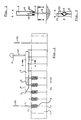
- Figure 1 shows a mould string consisting of mould parts 6, each of which on each side of a parting surface 7 forming one-half of the respective mould cavities (not visible on the drawing).
- an after-feeding reservoir 8 which during the pouring of molten metal into the mould is filled with molten metal that is to flow onwards from the after-feeding reservoir 8 to the mould cavity, commensurately with the contraction of the cast material in the mould cavity.
- the supply of pressure to the after-feeding reservoir 8 takes place by means of a pressure-supply conduit in the form of a lance 1, the latter initially being introduced into the mould part 6 to such an extent that the lance point 11 on the lance 1 is close to the after-feeding reservoir 8 without penetrating the last layer of material or plug just before the after-feeding reservoir 8.
- a pressure-supply conduit in the form of a lance 1 the latter initially being introduced into the mould part 6 to such an extent that the lance point 11 on the lance 1 is close to the after-feeding reservoir 8 without penetrating the last layer of material or plug just before the after-feeding reservoir 8.
- the lance 1 is introduced downwardly into the mould parts 6 in the direction of the arrow 30, the downward movement ceasing before the point penetrates the last layer just before the after-feeding reservoir 8.
- the lance 1 is advanced together with the mould string in the direction of the arrow 31 towards a pressure-feeding chain or a pressure-supply system. If, at this moment in time
- the pressure-supply system consists of a pressure source 4 supplying the pressure to a pressure chamber 3 enclosed by a pressure-chamber enclosure 9, cf. also Figures 2 and 3, in which is provided a longitudinal slot 2, sealed outwardly by means of lips 20, each from the respective side of the slot being pressed together along a lip parting surface 21, so that the pressure chamber 3 is substantially sealed outwardly.
- a pressing-down element 5 for pressing the lances 1 downwardly when they are under pressure.
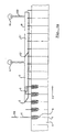
- the lance end with the pressure-supply end 10 lies in abutment with the lips 20 in the slot 2 and separates these lips 20 about their parting surfaces 21, so that the lance end 10 moves into the pressure chamber 3 and communicates with the pressure reigning in the latter.
- the lances 1 thus having been made to communicate with the presssure in the pressure chamber 3, they move along with the mould string forwardly towards the pressing-down element 5, in the example shown having a downwardly facing inclined surface, that presses the lance end down, when the lance is advanced with the mould string in the direction of the arrow 31.
- the lance point 11 penetrates the last material layer or plug just before the after-feeding reservoir 8.
- the after-feeding reservoir 8 is made to communicate pressure-wise with the pressure chamber 3 via the lance 1, so that pressure is applied to the after-feeding reservoir.
- This pressure is maintained during the advancement of the lance in the direction of the arrow 31 and along the full length of the pressure-supply system, until the lance leaves the latter through the end of the slot 2.
- the length of this advancement is so adapted, that the molten metal is solidified in the mould cavity in the mould part 6.
- the lances 1 together with the mould string have been moved out of the pressure-supply system, the lances 1 are removed from the mould part 6 in the manner illustrated by the arrow 32. This takes place before the mould parts 6 are advanced further along the cooling section to e.g. an extraction station.
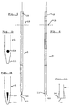
- the lances 1 can be in the form of simple tubes, but these tubes can advantageously be subjected to a certain processing.
- the point 11 on the tube or lance 1 having the exit aperture 15 can be pressed flat in the manner shown in Figure 5, and this compression of the point 11 on the lance 1 can be carried out to an extent so as to leave an exit slit 15 serving as an exit aperture. It is also possible, however, to compress the tube completely so as to close it as shown in Figures 5a and 5b.
- the point 11 will have a shape as shown in broken lines on Figures 6 and 6a, the point 11 initially been given a shape of a spatula as indicated in broken lines.
- the protruding part 16 of the point 11 can be cut or ground away, so that the point 11 becomes shaped like a chisel as shown in Figure 6a or like a needle as shown in Figure 6.
- the lance 1 can be provided with drilled holes 15 at its point in the manner shown in Figure 5b.
- the point 11 on the lance 1 and the exit apertures 15 can be given numerous shapes, chosen so as to be most expedient with regard to processing and the possibility of penetrating into the moulds without the exit apertures 15 being blocked.
- the lance can be provided with a collar 13 used for introducing and removing the lance 1 and/or to lie in sealing abutment against the lower side of the slot 2 when the lance is supplied with pressure from a pressure chamber 3.
- the lance 1 may simply be cut off like a tube serving as the supply end 10, or it can be cut at an angle or provided with slots or holes, all depending on what is most expedient with regard to introducing the lance between the lips 20 in the slot 2 and the pressing-down element 5.
- Figures 2 and 3 show partial sections of the pressure-supply system, showing how the lips 20 in the slot 12 fit sealingly about the lance 1 at the supply end 10.
- the lips 20 are made from elastically resilient material, that can be more or less compact, and the material can e.g. be foam rubber, or the lips 20 can be in the form of flexible tubes, to which pressure is applied from an external source, so that the pressure makes them press towards each other along the parting surface 21 or against a lance 1 in the manner shown in Figures 2 and 3.
- the pressure-supply system is in the form of a pressure chamber 3 having a slot 2 extending substantially as a straight line, but at the entry end (to the left in Figure 1) extending obliquely upward opposite to the direction of advancement of the mould parts as shown with the arrow 31.
- the slot 2 is substantially in the shape of a slot about a straight line, so that the lances can slide in gradually at the entry end of the slot 2 and with their supply ends 10 come into the pressure chamber 3 and slide along the slot 2 without being subjected to transverse forces.
- the pressure-chamber unit proper comprising the pressure chamber 3, the pressure-chamber enclosure 9, the slot 2 and the pressing-down element 5 can be constructed as an independent adjustable unit, capable of being adjusted depending on the path and the height, through which the lances 1 run, and the height they are to be pressed down to. If so, the pressing-down element 5 can also be made adjustable, so that it is not necessary to adjust the entire unit, but merely to adjust the height of the pressing-down element 5, if the pressing-down depth for the lances is to be altered.
- the pressing-down element 5 can, of course, be constructed in a different manner; thus, it can be placed outside of the pressure-chamber 3 and be adapted to co-operate with e.g.
- the pressure-supply unit itself can be fed from a stationary pressure source 4, the latter being connected to the pressure chamber 3 through a flexible tube 22.
- Figure 4a shows a pressure-supply system that is sub-divided into two pressure chambers 3 and 3'.
- This division can be advantageous when it is desirable to distribute the pressure losses on more than one pressure source along the pressure-supply section, or when it is desirable to increase the pressure along the pressure-supply section, the latter being possible by supplying one pressure from the pressure source 4 and a higher pressure from the pressure source 4'.
- the division into different pressure chambers can also be advantageous when the plant is used for varying production, so that when the full length of the pressure-section is not needed, i.e. that the castings have solidified upstream of the last pressure-chamber section, the supply of pressure to the latter can be cut off.
- Figure 4b shows an advantageous embodiment of the division in more than one pressure-chamber, when a high pressure is to be supplied by means of a succeeding pressure chamber, the latter being built into a preceding pressure chamber, so that the pressure difference across the lips 20 from one pressure chamber 3' to another pressure chamber 3 becomes less than in the case of the atmospheric pressure having reigned outside of the lips 20 at the pressure chamber 3'.
- the invention provides a possibility of using pressure-supply conduits in the form of simple lances that can be provided in a simple and low-cost manner by uncomplicated processing of standard tubes or in some other way.
- a particularly advantageous possibility consists in making the lances of the same material as is used for casting in the mould cavities concerned. In this manner it is achieved, partly that contamination of the castings with "foreign" material is avoided, partly that the lances after extraction, deburring and removal of risers etc. from the castings can form part of the total quantity of metal being returned for renewed melting - otherwise, a meticulous and hence labour-demanding sorting would be needed.
- the pressure sources 4 can simply be chosen in the form of standard pressure sources, e.g. compressors, with the requisite control arrangements.
- the replacement of parts subject to wear, i.e. the lips 20, can be carried out in a simple manner, when the pressure-chamber enclosure 9 is made to be open about the slot 2, so that the lips 20 can merely be removed from holding grooves and be replaced with new lips 20, the latter e.g. being in the form of an elastically resilient ribbon being cut in the requisite length for the slot 2.
- the pressure-supply system is extremely adaptable when the pressure chamber 3 or the pressure chambers 3, 3' is/are made as a unit capable of being moved about according to need, and is connected to one or a number of pressure sources 4, 4' via a pressure-supply conduit 22, e.g. in the form of a flexible tube, this making it possible to move and adjust the pressure-supply unit to the path being followed on the outside of the mould part 6 by pressure-supply conduits to the after-feeding reservoir, and this makes it possible to adapt the system to varying moulds, in which the pressure-supply conduits 1 in the form of lances can follow different paths.
Landscapes
- Engineering & Computer Science (AREA)
- Mechanical Engineering (AREA)
- Casting Support Devices, Ladles, And Melt Control Thereby (AREA)
- Casting Or Compression Moulding Of Plastics Or The Like (AREA)
- Feeding, Discharge, Calcimining, Fusing, And Gas-Generation Devices (AREA)
- Disintegrating Or Milling (AREA)
- Injection Moulding Of Plastics Or The Like (AREA)
- Mechanical Treatment Of Semiconductor (AREA)
- Molds, Cores, And Manufacturing Methods Thereof (AREA)
Claims (18)
- Procédé de post-alimentation active de moulages dans des moules (6) avec au moins un réservoir de post-alimentation (8), chacun communiquant avec au moins une cavité de moule, une pression étant appliquée, maintenue et éventuellement augmentée sur le métal en fusion dans au moins un réservoir de post-alimentation, éventuellement pendant le coulage du moule jusqu'à ce que le métal dans la(les) cavité(s) du moule se solidifie, caractérisé en ce quea) au moins un conduit ou lance d'alimentation en pression (1) est introduit dans le moule (6), etb) la pression est appliquée au réservoir de post-alimentation (8) en introduisant au moins un conduit ou lance d'alimentation (1) alimenté en pression dans ledit au moins un réservoir de post-alimentation (8).
- Procédé selon la revendication 1, caractérisé en ce que, par la disposition d'une barrière dans la forme par exemple du matériau du moule ou d'un bouchon entre le réservoir de post-alimentation (8) et le conduit ou la lance d'alimentation en pression (1), ledit au moins un conduit ou lance d'alimentation en pression étant alimenté en pression faite pour pénétrer ladite barrière de manière à communiquer avec le réservoir de post-alimentation (8).
- Procédé selon la revendication 1 ou 2, caractérisé par l'utilisation d'un conduit d'alimentation en pression (1) sous la forme d'une unité comprenant une extrémité d'alimentation en pression (10), par exemple sous la forme d'un tube relié de manière essentiellement rigide à une ouverture de sortie de pression (15), ledit conduit d'alimentation en pression (1) avec ladite ouverture de sortie de pression étant faits pour pénétrer dans le matériau du moule dans le réservoir de post-alimentation (8) en appliquant une force au conduit d'alimentation en pression (1) ou à proximité de l'extrémité de ce dernier (10).
- Procédé selon la revendication 1, 2 ou 3 et du type comprenant des coulées successives et un nombre de moules (6) étant avancés (31) le long d'un trajet de déplacement, caractérisé en ce que, pendant l'avance (31) du moule (6) le long dudit trajet, l'alimentation en pression audit conduit d'alimentation en pression (1) est assurée en faisant s'emboíter l'extrémité (10) dudit conduit d'alimentation en pression (1) dans une chaíne ou un système d'alimentation en pression en pressant ladite extrémité entre des lèvres élastiques (20) dans une rainure (2) de façon à faire communiquer ladite extrémité (10) avec une chambre de pression (3) derrière lesdites lèvres (20) et ladite rainure (2), dans laquelle règne une pression supérieure à la pression atmosphérique.
- Procédé selon les revendications 3 et 4, caractérisé en ce que, lorsque ladite extrémité (10) sur ledit conduit d'alimentation en pression (1) est dans la chambre de pression (3) derrière les lèvres (20) et la rainure (2), l'extrémité (10) est comprimée vers l'arrière en direction des lèvres (20) sans quitter la chambre de pression (3) à un degré tel que l'extrémité (11) sur ledit conduit d'alimentation en pression comprenant l'ouverture de sortie (15) est faite pour pénétrer dans le matériau du moule vers le réservoir de post-alimentation (8), de telle sorte que ledit conduit d'alimentation en pression (1) créé une communication de pression entre la chambre de pression (3) et le réservoir (8) par l'intermédiaire de ladite extrémité (10) et de l'ouverture de sortie (15) sur ledit conduit d'alimentation en pression (1).
- Procédé selon la revendication 4 ou 5, caractérisé par l'utilisation d'une chaíne d'alimentation en pression avec plus d'une section de pression (3, 3'), ladite extrémité (10), pendant son passage à travers la chaíne d'alimentation en pression, étant faite pour passer dans au moins une deuxième chambre de pression (3'), cette dernière étant faite pour communiquer avec le réservoir de post-alimentation (8) par l'intermédiaire de ladite extrémité (10).
- Procédé selon l'une quelconque des revendications 3 à 6, caractérisé en ce que la force de pressurisation et/ou la force d'extraction suivante est fournie par l'intermédiaire d'un élément (13) sur ledit conduit d'alimentation en pression (1), ledit élément (13) étant placé à une distance de ladite extrémité (10), ledit élément (13) étant spécifiquement sous la forme d'un collet (13), ce dernier étant éventuellement adapté pour venir en aboutement avec le moule (6) pour créer une étanchéité supplémentaire entre le moule (6) et le conduit d'alimentation en pression (1).
- Procédé selon l'une quelconque des revendications 4 à 7, caractérisé par l'utilisation d'un système d'alimentation en pression dans lequel la rainure (2) ou les rainures (2, 2') dans la chambre de pression (3, 3') est/sont disposée(s) dans une direction longitudinale parallèle à la direction de l'avance (31) de l'extrémité (10) sur le conduit d'alimentation en pression (1), et dans lequel la rainure (2) à son extrémité d'entrée est située à une première distance de la chaíne de moules, la rainure (2) ou les rainures (2, 2') s'étendent de manière oblique à partir de ladite extrémité d'entrée dans la direction du bas jusqu'à une deuxième distance, plus courte, de la chaíne de moules.
- Procédé selon l'une des revendications 1 à 8, caractérisé en ce que ce procédé est réalisé lors de la coulée dans des moules (6) présentant des surfaces de cloisonnement horizontal ou vertical (7) ou des surfaces de cloisonnement faisant des angles arbitraires avec les surfaces horizontales.
- Elément d'alimentation en pression (1) pour réaliser le procédé selon une des revendications 1 à 9, l'élément d'alimentation en pression (1) étant en forme de lance tubulaire et son extrémité arrière ayant une ouverture (10) sous la forme d'une extrémité d'entrée et son extrémité avant ayant un certain nombre d'ouvertures de sortie (15) et ladite lance (1) étant pointée vers l'extrémité comprenant l'ouverture de sortie (15) ou les ouvertures et ladite lance étant adaptée pour être introduite dans un moule (6) de telle sorte que ladite ouverture ou ouvertures de sortie (15) communique avec le réservoir de post-alimentation (8) dudit moule (6) et ladite lance (1) étant munie d'un élément en saillie (13), de préférence un collet situé à une certaine distance de l'extrémité d'entrée (10) de la lance.
- Elément d'alimentation en pression selon la revendication 10, la forme pointue (11) étant réalisée en comprimant l'extrémité dans un plan et en meulant ensuite les côtés dans ce plan.
- Elément d'alimentation en pression selon la revendication 10 ou 11, ladite lance (1) étant munie d'un revêtement ou d'une finition noire à au moins l'extrémité la plus proche des ouvertures de sortie (15).
- Système d'alimentation en pression pour réaliser le procédé selon une des revendications 4 à 10, caractérisé en ce qu'au moins une chambre de pression (3) adaptée à être alimentée en pression à partir d'au moins une source de pression (4), ladite chambre de pression (3) étant munie d'une rainure (2) fermée par des lèvres élastiques (20) exerçant une pression de chaque côté correspondant de ladite rainure (2), étanchéifiant mutuellement leur aboutement autour d'une surface de cloisonnement (21), ladite rainure (2) et lesdites lèvres (20) ayant une forme et étant dimensionnées pour recevoir une extrémité (10) sur un élément d'alimentation en pression (1) selon l'une quelconque des revendications 10 à 14 de telle sorte que ladite extrémité (10) puisse être déplacée dans le sens longitudinal de la rainure et dans la direction de l'avance (31) dudit moule (6), lesdites lèvres (20) encerclant, pendant cette avance, ladite extrémité (10) de manière étanche à l'air sur leurs surfaces de cloisonnement (21).
- Système d'alimentation en pression selon la revendication 13, caractérisé en ce que ladite rainure (2) ou lesdites rainures (2, 2') provenant de l'extrémité amont s'étendent premièrement vers le bas de manière inclinée puis globalement parallèle à la direction de l'avance (31) des moules (6).
- Système d'alimentation en pression selon la revendication 13 ou 14, caractérisé en ce que le nombre de chambres de pression (3, 3') sont disposées les unes derrière les autres et en ce que les chambres de pression (3, 3') sont séparées mutuellement au moyen d'une ou plusieurs rainures (2, 2') du même type que décrit dans la revendication 13.
- Système d'alimentation en pression selon la revendication 15, caractérisé en ce que dans une chambre de pression suivante (3'), la rainure (2') s'étend au-delà de la rainure (2) de la chambre de pression précédente (3), de telle sorte que ladite deuxième rainure (2') s'étend au-dessus de ladite première rainure (2) vers l'intérieur contre (3') ou à l'intérieur de ladite chambre de pression (3, 3').
- Système d'alimentation en pression selon une des revendications 13 à 16, caractérisé en ce que lesdites lèvres (20) sont constituées d'un matériau élastique, par exemple de mousse de caoutchouc.
- Système d'alimentation en pression selon une des revendications 13 à 17, caractérisé en ce que lesdites lèvres (20) ont la forme de tubes flexibles pouvant être pressurisés par une source externe de pression.
Applications Claiming Priority (3)
| Application Number | Priority Date | Filing Date | Title |
|---|---|---|---|
| DK30397 | 1997-03-18 | ||
| DK30397 | 1997-03-18 | ||
| PCT/DK1998/000102 WO1998041341A1 (fr) | 1997-03-18 | 1998-03-18 | Procede d'approvisionnement complementaire de moulages, element d'alimentation sous pression et systeme d'alimentation sous pression afferents |
Publications (2)
| Publication Number | Publication Date |
|---|---|
| EP0968063A1 EP0968063A1 (fr) | 2000-01-05 |
| EP0968063B1 true EP0968063B1 (fr) | 2002-11-27 |
Family
ID=8092033
Family Applications (1)
| Application Number | Title | Priority Date | Filing Date |
|---|---|---|---|
| EP98907909A Expired - Lifetime EP0968063B1 (fr) | 1997-03-18 | 1998-03-18 | Procede d'approvisionnement complementaire de moulages, element d'alimentation sous pression et systeme d'alimentation sous pression afferents |
Country Status (13)
| Country | Link |
|---|---|
| US (1) | US6283196B1 (fr) |
| EP (1) | EP0968063B1 (fr) |
| JP (1) | JP3188279B2 (fr) |
| KR (1) | KR100334977B1 (fr) |
| CN (1) | CN1326643C (fr) |
| AT (1) | ATE228407T1 (fr) |
| AU (1) | AU6611398A (fr) |
| BR (1) | BR9808914A (fr) |
| DE (1) | DE69809720T2 (fr) |
| ES (1) | ES2187933T3 (fr) |
| RO (1) | RO120462B1 (fr) |
| RU (1) | RU2167740C1 (fr) |
| WO (1) | WO1998041341A1 (fr) |
Families Citing this family (6)
| Publication number | Priority date | Publication date | Assignee | Title |
|---|---|---|---|---|
| DE102004052231A1 (de) * | 2004-10-27 | 2006-05-11 | Ks Kolbenschmidt Gmbh | Verfahren zur Serienherstellung von Kolben für Brennkraftmaschinen unter Gasdruckeinwirkung |
| US20080057385A1 (en) * | 2006-08-30 | 2008-03-06 | Shin-Etsu Chemical Co., Ltd. | Separator for non-aqueous secondary battery, making method, and non-aqueous electrolyte secondary battery |
| MX360305B (es) * | 2012-10-16 | 2018-10-26 | Monsanto Technology Llc | Metodos y composiciones para controlar la infeccion viral en plantas. |
| US9950363B2 (en) | 2013-09-30 | 2018-04-24 | Hitachi Metals, Ltd. | Casting apparatus and method for producing castings using it |
| CN106077517B (zh) * | 2016-07-27 | 2017-09-26 | 三鑫重工机械有限公司 | 一种高速钢轧辊的铸造方法 |
| US11772156B2 (en) * | 2021-01-20 | 2023-10-03 | GM Global Technology Operations LLC | In-line pressurization chamber for casting |
Citations (1)
| Publication number | Priority date | Publication date | Assignee | Title |
|---|---|---|---|---|
| FR2232376A1 (en) * | 1973-06-05 | 1975-01-03 | Scholler Andre | Injecting catalyst gas into moulding boxes - using jet-pipes which penetrate moulding sand |
Family Cites Families (6)
| Publication number | Priority date | Publication date | Assignee | Title |
|---|---|---|---|---|
| US2568428A (en) * | 1949-09-09 | 1951-09-18 | Irvin A Billiar | Mold with riser and exothermic insert |
| US3566952A (en) * | 1967-10-26 | 1971-03-02 | Wyman Curtis Lane | Pressure feeding of casting using a feeder head |
| FR2651453B2 (fr) * | 1989-09-07 | 1994-03-25 | Pechiney Aluminium | Perfectionnement au procede de moulage a mousse perdue et sous pression de pieces metalliques. |
| BR9408470A (pt) * | 1994-01-03 | 1997-08-19 | Georg Fischer Disa As | Método e equipamento para alimentação de vazios de retratação em fundidos de metais |
| DK77694A (da) * | 1994-06-29 | 1995-12-30 | Dansk Ind Syndikat | Fremgangsmåde og indretning til ved udstøbning mod tyngdekraften af støbeforme, især vådsandforme, med navnlig letoxiderbare metaller eller metallegeringer af afslutte støbeprocessen |
| DE19531551A1 (de) * | 1995-08-28 | 1997-03-06 | Bruehl Eisenwerk | Verfahren zum Herstellen von Gußstücken aus Leichtmetall und verlorene Form auf Basis von Sand hierfür |
-
1998
- 1998-03-18 DE DE69809720T patent/DE69809720T2/de not_active Expired - Fee Related
- 1998-03-18 AU AU66113/98A patent/AU6611398A/en not_active Abandoned
- 1998-03-18 JP JP54004198A patent/JP3188279B2/ja not_active Expired - Fee Related
- 1998-03-18 BR BR9808914-5A patent/BR9808914A/pt not_active IP Right Cessation
- 1998-03-18 RO RO99-00868A patent/RO120462B1/ro unknown
- 1998-03-18 KR KR1019997007493A patent/KR100334977B1/ko not_active IP Right Cessation
- 1998-03-18 US US09/380,754 patent/US6283196B1/en not_active Expired - Fee Related
- 1998-03-18 ES ES98907909T patent/ES2187933T3/es not_active Expired - Lifetime
- 1998-03-18 CN CNB988026570A patent/CN1326643C/zh not_active Expired - Fee Related
- 1998-03-18 EP EP98907909A patent/EP0968063B1/fr not_active Expired - Lifetime
- 1998-03-18 AT AT98907909T patent/ATE228407T1/de not_active IP Right Cessation
- 1998-03-18 WO PCT/DK1998/000102 patent/WO1998041341A1/fr active IP Right Grant
- 1998-03-18 RU RU99121857/02A patent/RU2167740C1/ru not_active IP Right Cessation
Patent Citations (1)
| Publication number | Priority date | Publication date | Assignee | Title |
|---|---|---|---|---|
| FR2232376A1 (en) * | 1973-06-05 | 1975-01-03 | Scholler Andre | Injecting catalyst gas into moulding boxes - using jet-pipes which penetrate moulding sand |
Also Published As
| Publication number | Publication date |
|---|---|
| CN1326643C (zh) | 2007-07-18 |
| CN1248187A (zh) | 2000-03-22 |
| DE69809720D1 (de) | 2003-01-09 |
| EP0968063A1 (fr) | 2000-01-05 |
| BR9808914A (pt) | 2000-08-01 |
| RU99121857A (ru) | 2005-01-20 |
| US6283196B1 (en) | 2001-09-04 |
| ATE228407T1 (de) | 2002-12-15 |
| JP3188279B2 (ja) | 2001-07-16 |
| KR20000071203A (ko) | 2000-11-25 |
| ES2187933T3 (es) | 2003-06-16 |
| KR100334977B1 (ko) | 2002-05-02 |
| JP2000511469A (ja) | 2000-09-05 |
| RU2167740C1 (ru) | 2001-05-27 |
| DE69809720T2 (de) | 2003-07-17 |
| AU6611398A (en) | 1998-10-12 |
| WO1998041341A1 (fr) | 1998-09-24 |
| RO120462B1 (ro) | 2006-02-28 |
Similar Documents
| Publication | Publication Date | Title |
|---|---|---|
| EP0738192B1 (fr) | Procede et materiel permettant d'alimenter des cavites de retrait dans les moulages en metal | |
| CA2119566C (fr) | Procede de coulee | |
| US5908065A (en) | Apparatus and method for squeeze casting | |
| EP0968063B1 (fr) | Procede d'approvisionnement complementaire de moulages, element d'alimentation sous pression et systeme d'alimentation sous pression afferents | |
| US6997231B1 (en) | Method for vacuum diecasting and diecasting mould | |
| US3903956A (en) | Die casting machine with parting line feed | |
| AU708985B2 (en) | Apparatus and method for squeeze casting | |
| CN105555496B (zh) | 高压铸造设备及方法 | |
| US5595236A (en) | Vertical squeeze casting apparatus | |
| CN105033206A (zh) | 涉及用于连续或半连续金属铸造的设备的装置 | |
| US5636680A (en) | Method and device for terminating the casting process after non-gravity casting of moulds, especially green-sand moulds, particularly with easily oxidable metals or metal alloys | |
| JPH03155444A (ja) | 竪型鋳造方法および装置 | |
| EP1240960B1 (fr) | Procédé et dispositif pour la désoxydation pendant la coulée | |
| CA2285742C (fr) | Moulage par pression de bornes de batterie | |
| SU827259A1 (ru) | Установка дл лить с противодавлением | |
| JPH03456A (ja) | 鋳造装置 | |
| US7270169B2 (en) | Method and apparatus for pouring several moulds in a mould-string plant in one pouring operation | |
| CN1819883A (zh) | 水平式直接冷硬铸造设备和方法 | |
| EP1682293A2 (fr) | Dispositif et procede servant a refroidir une charge de coulage | |
| KR900000003Y1 (ko) | 고압 주조장치 | |
| JPH0545346B2 (fr) | ||
| WO2002090020A1 (fr) | Procede et dispositif destines a former rapidement et economiquement au moins un produit moule sous pression sans gaspillage de matiere de moulage | |
| HU187423B (en) | Pneumatic-piston method for pressure casting metals and other materials as well as apparatus for carrying out the method | |
| CS213876B1 (cs) | Zařízení na lití kovů pod tlakem | |
| JPS5855162A (ja) | 鋳造品の離型方法及び同装置 |
Legal Events
| Date | Code | Title | Description |
|---|---|---|---|
| PUAI | Public reference made under article 153(3) epc to a published international application that has entered the european phase |
Free format text: ORIGINAL CODE: 0009012 |
|
| 17P | Request for examination filed |
Effective date: 19991018 |
|
| AK | Designated contracting states |
Kind code of ref document: A1 Designated state(s): AT BE CH DE DK ES FI FR GB GR IE IT LI LU MC NL PT SE |
|
| 17Q | First examination report despatched |
Effective date: 20010608 |
|
| GRAG | Despatch of communication of intention to grant |
Free format text: ORIGINAL CODE: EPIDOS AGRA |
|
| RAP1 | Party data changed (applicant data changed or rights of an application transferred) |
Owner name: DISA INDUSTRIES A/S |
|
| GRAG | Despatch of communication of intention to grant |
Free format text: ORIGINAL CODE: EPIDOS AGRA |
|
| GRAH | Despatch of communication of intention to grant a patent |
Free format text: ORIGINAL CODE: EPIDOS IGRA |
|
| GRAH | Despatch of communication of intention to grant a patent |
Free format text: ORIGINAL CODE: EPIDOS IGRA |
|
| GRAA | (expected) grant |
Free format text: ORIGINAL CODE: 0009210 |
|
| AK | Designated contracting states |
Kind code of ref document: B1 Designated state(s): AT BE CH DE DK ES FI FR GB GR IE IT LI LU MC NL PT SE |
|
| PG25 | Lapsed in a contracting state [announced via postgrant information from national office to epo] |
Ref country code: NL Free format text: LAPSE BECAUSE OF FAILURE TO SUBMIT A TRANSLATION OF THE DESCRIPTION OR TO PAY THE FEE WITHIN THE PRESCRIBED TIME-LIMIT Effective date: 20021127 Ref country code: LI Free format text: LAPSE BECAUSE OF FAILURE TO SUBMIT A TRANSLATION OF THE DESCRIPTION OR TO PAY THE FEE WITHIN THE PRESCRIBED TIME-LIMIT Effective date: 20021127 Ref country code: IT Free format text: LAPSE BECAUSE OF FAILURE TO SUBMIT A TRANSLATION OF THE DESCRIPTION OR TO PAY THE FEE WITHIN THE PRESCRIBED TIME-LIMIT;WARNING: LAPSES OF ITALIAN PATENTS WITH EFFECTIVE DATE BEFORE 2007 MAY HAVE OCCURRED AT ANY TIME BEFORE 2007. THE CORRECT EFFECTIVE DATE MAY BE DIFFERENT FROM THE ONE RECORDED. Effective date: 20021127 Ref country code: GR Free format text: LAPSE BECAUSE OF FAILURE TO SUBMIT A TRANSLATION OF THE DESCRIPTION OR TO PAY THE FEE WITHIN THE PRESCRIBED TIME-LIMIT Effective date: 20021127 Ref country code: FI Free format text: LAPSE BECAUSE OF FAILURE TO SUBMIT A TRANSLATION OF THE DESCRIPTION OR TO PAY THE FEE WITHIN THE PRESCRIBED TIME-LIMIT Effective date: 20021127 Ref country code: CH Free format text: LAPSE BECAUSE OF FAILURE TO SUBMIT A TRANSLATION OF THE DESCRIPTION OR TO PAY THE FEE WITHIN THE PRESCRIBED TIME-LIMIT Effective date: 20021127 Ref country code: BE Free format text: LAPSE BECAUSE OF FAILURE TO SUBMIT A TRANSLATION OF THE DESCRIPTION OR TO PAY THE FEE WITHIN THE PRESCRIBED TIME-LIMIT Effective date: 20021127 Ref country code: AT Free format text: LAPSE BECAUSE OF FAILURE TO SUBMIT A TRANSLATION OF THE DESCRIPTION OR TO PAY THE FEE WITHIN THE PRESCRIBED TIME-LIMIT Effective date: 20021127 |
|
| REF | Corresponds to: |
Ref document number: 228407 Country of ref document: AT Date of ref document: 20021215 Kind code of ref document: T |
|
| REG | Reference to a national code |
Ref country code: GB Ref legal event code: FG4D |
|
| REG | Reference to a national code |
Ref country code: CH Ref legal event code: EP |
|
| REG | Reference to a national code |
Ref country code: IE Ref legal event code: FG4D |
|
| REF | Corresponds to: |
Ref document number: 69809720 Country of ref document: DE Date of ref document: 20030109 |
|
| PG25 | Lapsed in a contracting state [announced via postgrant information from national office to epo] |
Ref country code: SE Free format text: LAPSE BECAUSE OF FAILURE TO SUBMIT A TRANSLATION OF THE DESCRIPTION OR TO PAY THE FEE WITHIN THE PRESCRIBED TIME-LIMIT Effective date: 20030227 Ref country code: PT Free format text: LAPSE BECAUSE OF FAILURE TO SUBMIT A TRANSLATION OF THE DESCRIPTION OR TO PAY THE FEE WITHIN THE PRESCRIBED TIME-LIMIT Effective date: 20030227 Ref country code: DK Free format text: LAPSE BECAUSE OF FAILURE TO SUBMIT A TRANSLATION OF THE DESCRIPTION OR TO PAY THE FEE WITHIN THE PRESCRIBED TIME-LIMIT Effective date: 20030227 |
|
| PG25 | Lapsed in a contracting state [announced via postgrant information from national office to epo] |
Ref country code: LU Free format text: LAPSE BECAUSE OF NON-PAYMENT OF DUE FEES Effective date: 20030318 Ref country code: IE Free format text: LAPSE BECAUSE OF NON-PAYMENT OF DUE FEES Effective date: 20030318 |
|
| PG25 | Lapsed in a contracting state [announced via postgrant information from national office to epo] |
Ref country code: MC Free format text: LAPSE BECAUSE OF NON-PAYMENT OF DUE FEES Effective date: 20030331 |
|
| ET | Fr: translation filed | ||
| NLV1 | Nl: lapsed or annulled due to failure to fulfill the requirements of art. 29p and 29m of the patents act | ||
| REG | Reference to a national code |
Ref country code: CH Ref legal event code: PL |
|
| REG | Reference to a national code |
Ref country code: ES Ref legal event code: FG2A Ref document number: 2187933 Country of ref document: ES Kind code of ref document: T3 |
|
| PLBE | No opposition filed within time limit |
Free format text: ORIGINAL CODE: 0009261 |
|
| STAA | Information on the status of an ep patent application or granted ep patent |
Free format text: STATUS: NO OPPOSITION FILED WITHIN TIME LIMIT |
|
| 26N | No opposition filed |
Effective date: 20030828 |
|
| REG | Reference to a national code |
Ref country code: IE Ref legal event code: MM4A |
|
| PGFP | Annual fee paid to national office [announced via postgrant information from national office to epo] |
Ref country code: FR Payment date: 20060307 Year of fee payment: 9 |
|
| PGFP | Annual fee paid to national office [announced via postgrant information from national office to epo] |
Ref country code: ES Payment date: 20060330 Year of fee payment: 9 |
|
| PGFP | Annual fee paid to national office [announced via postgrant information from national office to epo] |
Ref country code: DE Payment date: 20070331 Year of fee payment: 10 |
|
| GBPC | Gb: european patent ceased through non-payment of renewal fee |
Effective date: 20070318 |
|
| REG | Reference to a national code |
Ref country code: FR Ref legal event code: ST Effective date: 20071130 |
|
| PG25 | Lapsed in a contracting state [announced via postgrant information from national office to epo] |
Ref country code: GB Free format text: LAPSE BECAUSE OF NON-PAYMENT OF DUE FEES Effective date: 20070318 |
|
| REG | Reference to a national code |
Ref country code: ES Ref legal event code: FD2A Effective date: 20070319 |
|
| PG25 | Lapsed in a contracting state [announced via postgrant information from national office to epo] |
Ref country code: FR Free format text: LAPSE BECAUSE OF NON-PAYMENT OF DUE FEES Effective date: 20070402 Ref country code: ES Free format text: LAPSE BECAUSE OF NON-PAYMENT OF DUE FEES Effective date: 20070319 |
|
| PGFP | Annual fee paid to national office [announced via postgrant information from national office to epo] |
Ref country code: GB Payment date: 20060310 Year of fee payment: 9 |
|
| PG25 | Lapsed in a contracting state [announced via postgrant information from national office to epo] |
Ref country code: DE Free format text: LAPSE BECAUSE OF NON-PAYMENT OF DUE FEES Effective date: 20081001 |