EP0967145A2 - Fahrradbremse mit von Hebelelementen nachgestellten Bremsschuhen - Google Patents
Fahrradbremse mit von Hebelelementen nachgestellten Bremsschuhen Download PDFInfo
- Publication number
- EP0967145A2 EP0967145A2 EP99304329A EP99304329A EP0967145A2 EP 0967145 A2 EP0967145 A2 EP 0967145A2 EP 99304329 A EP99304329 A EP 99304329A EP 99304329 A EP99304329 A EP 99304329A EP 0967145 A2 EP0967145 A2 EP 0967145A2
- Authority
- EP
- European Patent Office
- Prior art keywords
- brake
- link member
- brake arm
- shaft
- link
- Prior art date
- Legal status (The legal status is an assumption and is not a legal conclusion. Google has not performed a legal analysis and makes no representation as to the accuracy of the status listed.)
- Granted
Links
- 230000000717 retained effect Effects 0.000 claims 1
- 230000008878 coupling Effects 0.000 description 10
- 238000010168 coupling process Methods 0.000 description 10
- 238000005859 coupling reaction Methods 0.000 description 10
- 230000000712 assembly Effects 0.000 description 7
- 238000000429 assembly Methods 0.000 description 7
- 238000006073 displacement reaction Methods 0.000 description 1
- 238000004519 manufacturing process Methods 0.000 description 1
- 238000012986 modification Methods 0.000 description 1
- 230000004048 modification Effects 0.000 description 1
Images


Classifications
-
- B—PERFORMING OPERATIONS; TRANSPORTING
- B62—LAND VEHICLES FOR TRAVELLING OTHERWISE THAN ON RAILS
- B62L—BRAKES SPECIALLY ADAPTED FOR CYCLES
- B62L1/00—Brakes; Arrangements thereof
- B62L1/02—Brakes; Arrangements thereof in which cycle wheels are engaged by brake elements
- B62L1/06—Brakes; Arrangements thereof in which cycle wheels are engaged by brake elements the wheel rim being engaged
- B62L1/10—Brakes; Arrangements thereof in which cycle wheels are engaged by brake elements the wheel rim being engaged by the elements moving substantially parallel to the wheel axis
- B62L1/14—Brakes; Arrangements thereof in which cycle wheels are engaged by brake elements the wheel rim being engaged by the elements moving substantially parallel to the wheel axis the elements being mounted on levers pivotable about different axes
-
- B—PERFORMING OPERATIONS; TRANSPORTING
- B62—LAND VEHICLES FOR TRAVELLING OTHERWISE THAN ON RAILS
- B62L—BRAKES SPECIALLY ADAPTED FOR CYCLES
- B62L1/00—Brakes; Arrangements thereof
- B62L1/005—Brakes; Arrangements thereof constructional features of brake elements, e.g. fastening of brake blocks in their holders
-
- Y—GENERAL TAGGING OF NEW TECHNOLOGICAL DEVELOPMENTS; GENERAL TAGGING OF CROSS-SECTIONAL TECHNOLOGIES SPANNING OVER SEVERAL SECTIONS OF THE IPC; TECHNICAL SUBJECTS COVERED BY FORMER USPC CROSS-REFERENCE ART COLLECTIONS [XRACs] AND DIGESTS
- Y10—TECHNICAL SUBJECTS COVERED BY FORMER USPC
- Y10T—TECHNICAL SUBJECTS COVERED BY FORMER US CLASSIFICATION
- Y10T74/00—Machine element or mechanism
- Y10T74/20—Control lever and linkage systems
- Y10T74/20576—Elements
- Y10T74/20582—Levers
- Y10T74/206—Adjustable
Definitions
- the present invention is directed to bicycle braking devices and, more particularly, to a cantilever brake having brake shoes attached to adjustable links so that the lateral position of the brake shoes may be adjusted.
- a cantilever brake ordinarily comprises a pair of opposed brake arm assemblies, wherein each brake arm assembly includes a brake arm having an upper portion and a lower portion. A brake shoe is disposed on an intermediate portion of each brake arm such that the brake shoes face each other. The lower portion of each brake arm is pivotally attached to the bicycle frame, and a brake control cable coupling assembly is disposed on the upper portion of each brake arm.
- each brake arm In one type of cantilever brake the upper portion of each brake arm is angled outwardly from the wheel rim and the brake is operated by pulling generally upwardly on a brake control cable wire attached to the cable coupling assembly of each brake arm.
- the brake arms In another type of cantilever brake the brake arms are essentially straight. In this case an outer casing of the brake control cable is attached to the brake control cable coupling assembly of one brake arm and an inner wire of the brake control cable is attached to the brake control cable coupling assembly of the other brake arm. This type of brake is very efficient because the force of the brake control cable is applied substantially perpendicular to each brake arm.
- a brake arm assembly designed for road bikes will be angled too far outwardly when the brake shoe contacts the rim of a mountain bike.
- different brake shoe assemblies must be designed for different bicycles if optimum performance is desired. This increased design, tooling and manufacturing costs for the manufacturer and inventory costs for the dealer, and it prevents the bicyclist from using one type of brake arm assembly with different style bicycles.
- the present invention is directed to a bicycle brake arm assembly which can be optimally used with bicycles having different configurations, especially those with varying rim widths.
- a bicycle brake apparatus according to claim 1. Rotation of the adjusting member therefore adjusts the angle and position of the brake shoe relative to the brake arm.
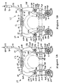
- FIG. 1A and 1B are rear views of a particular embodiment of a brake apparatus 10 according to the present invention
- Figures 2 and 3 are partially and completely exploded views, respectively, of part of brake apparatus 10.
- Brake apparatus 10 has a pair of brake arm assemblies 14A, 14B, wherein each brake arm assembly 14A, 14B includes a brake arm 18A, 18B having an upper portion 22A, 22B and a lower portion 26A, 26B and a link member assembly 30A, 30B.
- Each link member assembly 30A, 30B comprises a link member 32A, 32B, each having an upper portion 34A, 34B and a lower portion 38A, 38B.
- a shoe attachment member in the form of a flange 42A, 42B is disposed on the upper portion 34A, 34B of each link member 32A, 32B for supporting a corresponding brake shoe 44A, 44B.
- the lower portion 26A, 26B of each brake arm 18A, 18B and the lower portion 38A, 38B of each link member 32A, 32B are pivotably supported on a pivot shaft 43A, 43B so that each link member assembly 30A, 30B can pivot relative to its corresponding brake arm 18A, 18B around a common pivot axis X.
- the lower portion 26A of brake arm 18A has an opening 88A that pivotably fits around pivot shaft 43A
- the lower portion 38A of link member 32A has an opening 90A that pivotably fits around pivot shaft 43A.
- the entire assembly is held in place by a bolt 96A and washer 98A, wherein bolt 96A extends through the opening 88A in the lower portion 26A of brake arm 18A, through the opening 90A in the lower portion 38A of link member 32A, and into a threaded opening 92A in pivot shaft 43A.
- a brake control cable coupling assembly 40 comprising a screw 41 ( Figure 3), a washer 42 and a fixing plate 43 is disposed on the upper portion 22A of brake arm 18A for coupling brake arm assembly 14A to an inner wire 44 (Figs 1A and 1B) of a brake control cable 48, and a brake control cable coupling assembly 52 is coupled to the upper portion 22B of brake arm 18B for coupling brake arm assembly 14B to an outer casing 56 of control cable 48.
- brake control cable coupling assembly 52 comprises a connecting arm 60 having a first end 64 pivotably coupled to upper portion 22B of brake arm 18B through a pivot coupling 68 and a second end 72 attached to one end 76 of a guide tube 80.
- One end 82 of a bellows seal 84 is attached to end 76 of guide tube 80.
- One end 82 of a bellows seal 84 is attached to end 76 of guide tube 80, and the other end 86 of bellows seal 84 sealingly engages inner wire 44 of brake control cable 48.
- a casing receptacle 90 is disposed on the other end 94 of guide tube 80 for receiving outer casing 56 therein.
- brake arm assembly 14A Because of the otherwise symmetrical nature of brake arm assemblies 14A and 14B, only the details of brake arm assembly 14A will now be described in detail.
- a spring cover 100A having an opening 102A that fits around pivot shaft 43A has an abutment 104A that abuts against an abutment 108A on link member 32A.
- a spring retainer 110A has an opening 112A that fits around pivot shaft 43A so that spring retainer 110A is disposed between link member 32A and spring cover 100A.
- Spring retainer 110A has a spring retaining opening 114A and an adjustment abutment 115A.
- Spring retaining opening 114A retains an end 118A of a spring 120A, and adjustment abutment 115A abuts against an end of an adjusting screw 124A that screws into a threaded opening 128A in spring cover 100A.
- the other end 130A of spring 120A is fixed to the bicycle frame (not shown).
- the biasing force of spring 120A may be adjusted by turning adjusting screw 124A which, in turn, rotates spring retainer 110A around pivot shaft 43A to move spring end 118A.
- brake shoe 44A has a threaded shaft 148A that extends through a vertically elongated slot 150A in flange 42A and is fixed to flange 42A through convex washers 150A, 152A, concave washers 154A, 156A, fastening washer 158A and fastening nut 160A in a known manner that allows the vertical position and mounting angle of brake shoe 44A to be varied.
- a fixing shaft in the form of a screw 161A extends snugly through a shaft opening 162A in the upper portion 22A of brake arm 18A and through a shaft opening 164A in the upper portion 34A of link member 32A.
- a fixing nut 168A and fixing washer 172A mates with fixing screw 161A to fix the angle of link member 32A relative to brake arm 18A.
- the inner diameter of shaft opening 164A is substantially greater than the outer diameter of screw 161A, and an adjusting member 180A having an adjusting opening or slot 182A is disposed in shaft opening 164A for snugly receiving screw 161A therethrough at a position offset from a centre of shaft opening 164A.
- brake device 10 it is first determined whether brake device 10 will be used with a wide rim or a narrow rim. If a narrow rim is used, then adjusting members 180A, 180B are disposed in their respective shaft openings 164A, 164B so that adjusting openings 182A, 182B (only adjusting opening 182A is shown in Figure 3) open laterally outwardly to set the angular position of link member 32A relative to brake arm 18A as shown in Figure 1A.
- adjusting members 180A, 180B are disposed in their respective shaft openings 164A, 164B so that adjusting openings 182A, 182B open laterally inwardly to set the angular position of link members 32A, 32B relative to brake arms 18A, 18B as shown in Figure 1B.
- adjusting members 180A, 180B may be set at any intermediate position between these extremities, depending upon the width of the wheel rim.
Landscapes
- Engineering & Computer Science (AREA)
- Mechanical Engineering (AREA)
- Braking Arrangements (AREA)
- Steering Devices For Bicycles And Motorcycles (AREA)
Applications Claiming Priority (2)
| Application Number | Priority Date | Filing Date | Title |
|---|---|---|---|
| US09/103,980 US6039153A (en) | 1998-06-22 | 1998-06-22 | Bicycle brake with link-adjusted brake shoes |
| US103980 | 1998-06-22 |
Publications (3)
| Publication Number | Publication Date |
|---|---|
| EP0967145A2 true EP0967145A2 (de) | 1999-12-29 |
| EP0967145A3 EP0967145A3 (de) | 2002-07-31 |
| EP0967145B1 EP0967145B1 (de) | 2004-02-04 |
Family
ID=22298053
Family Applications (1)
| Application Number | Title | Priority Date | Filing Date |
|---|---|---|---|
| EP99304329A Expired - Lifetime EP0967145B1 (de) | 1998-06-22 | 1999-06-03 | Fahrradbremse mit von Hebelelementen nachgestellten Bremsschuhen |
Country Status (10)
| Country | Link |
|---|---|
| US (1) | US6039153A (de) |
| EP (1) | EP0967145B1 (de) |
| CN (1) | CN1098784C (de) |
| AT (1) | ATE258867T1 (de) |
| CZ (1) | CZ295598B6 (de) |
| DE (1) | DE69914534T2 (de) |
| PL (1) | PL190986B1 (de) |
| RU (1) | RU2223194C2 (de) |
| SK (1) | SK83899A3 (de) |
| TW (1) | TW499379B (de) |
Families Citing this family (12)
| Publication number | Priority date | Publication date | Assignee | Title |
|---|---|---|---|---|
| US6349799B1 (en) * | 2000-03-15 | 2002-02-26 | Shimano Inc. | Bicycle brake device |
| US6877588B1 (en) * | 2004-04-30 | 2005-04-12 | Tektro Technology Corporation | Bike cantilever brake arm |
| US7651424B2 (en) * | 2006-07-25 | 2010-01-26 | Shimano Inc. | Bicycle front derailleur |
| US8127896B2 (en) * | 2008-03-17 | 2012-03-06 | Bikebiz Iii, Inc. | Cantilever brake device |
| US8522929B2 (en) * | 2009-12-10 | 2013-09-03 | Shimano Inc. | Bicycle rim brake assembly |
| US20140190775A1 (en) * | 2013-01-10 | 2014-07-10 | Felt Racing, Llc | Brake having custom kinematics and wide range adjustability for wide and narrow rims |
| WO2014153367A1 (en) * | 2013-03-18 | 2014-09-25 | Fattahi Aziz | Bicycle brake device and assembly |
| US9340255B2 (en) * | 2014-09-30 | 2016-05-17 | Tektro Technology Corp | Adjustable shoe mounting structure for bicycle brake device |
| TWI564211B (zh) * | 2015-12-30 | 2017-01-01 | 溫芫鋐 | 刹車系統與v夾刹車器 |
| CN105460151A (zh) * | 2016-01-07 | 2016-04-06 | 温芫鋐 | 刹车系统与v夹刹车器 |
| TWI640451B (zh) * | 2017-11-17 | 2018-11-11 | 陳逸偉 | Brake block adjustment structure of bicycle brake |
| CN111958334B (zh) * | 2020-08-18 | 2021-03-12 | 广州市万力工艺制品有限公司 | 一种装配式家具连接结构精加工处理装置及处理工艺 |
Family Cites Families (7)
| Publication number | Priority date | Publication date | Assignee | Title |
|---|---|---|---|---|
| GB571477A (en) * | 1943-08-11 | 1945-08-27 | Doherty & Son Ltd J | Improvements in braking mechanism for cycles and the like |
| JPH02129985U (de) * | 1989-04-04 | 1990-10-26 | ||
| JPH03153485A (ja) * | 1989-11-08 | 1991-07-01 | Yoshigai Kikai Kinzoku Kk | 二輪車用ブレーキ装置 |
| JPH079692U (ja) * | 1993-07-26 | 1995-02-10 | 株式会社シマノ | 自転車用ブレーキ装置 |
| US5636716A (en) * | 1995-03-07 | 1997-06-10 | Shimano, Inc. | Bicycle brake device |
| CN2254864Y (zh) * | 1996-03-08 | 1997-05-28 | 张文湧 | 自行车复杠杆刹车装置 |
| US5743284A (en) * | 1996-09-18 | 1998-04-28 | Avid Enterprises, Inc. | Cantilever brake with pad attitude control |
-
1998
- 1998-06-22 US US09/103,980 patent/US6039153A/en not_active Expired - Lifetime
-
1999
- 1999-05-07 TW TW088107485A patent/TW499379B/zh not_active IP Right Cessation
- 1999-06-03 EP EP99304329A patent/EP0967145B1/de not_active Expired - Lifetime
- 1999-06-03 DE DE69914534T patent/DE69914534T2/de not_active Expired - Lifetime
- 1999-06-03 AT AT99304329T patent/ATE258867T1/de not_active IP Right Cessation
- 1999-06-16 CZ CZ19992175A patent/CZ295598B6/cs not_active IP Right Cessation
- 1999-06-18 SK SK838-99A patent/SK83899A3/sk unknown
- 1999-06-21 CN CN99108517A patent/CN1098784C/zh not_active Expired - Fee Related
- 1999-06-22 PL PL333896A patent/PL190986B1/pl unknown
- 1999-06-22 RU RU99113847/11A patent/RU2223194C2/ru not_active IP Right Cessation
Non-Patent Citations (1)
| Title |
|---|
| None |
Also Published As
| Publication number | Publication date |
|---|---|
| RU2223194C2 (ru) | 2004-02-10 |
| SK83899A3 (en) | 2000-01-18 |
| DE69914534D1 (de) | 2004-03-11 |
| US6039153A (en) | 2000-03-21 |
| DE69914534T2 (de) | 2004-12-23 |
| EP0967145B1 (de) | 2004-02-04 |
| EP0967145A3 (de) | 2002-07-31 |
| PL190986B1 (pl) | 2006-02-28 |
| CN1098784C (zh) | 2003-01-15 |
| CZ295598B6 (cs) | 2005-08-17 |
| CZ217599A3 (cs) | 2000-01-12 |
| CN1240183A (zh) | 2000-01-05 |
| TW499379B (en) | 2002-08-21 |
| ATE258867T1 (de) | 2004-02-15 |
Similar Documents
| Publication | Publication Date | Title |
|---|---|---|
| EP0967145B1 (de) | Fahrradbremse mit von Hebelelementen nachgestellten Bremsschuhen | |
| US5501301A (en) | Bicycle brake arm having a brake shoe clearance adjusting mechanism | |
| JP3571662B2 (ja) | ケーブル操作型ディスクブレーキ | |
| US6482115B2 (en) | Cable connecting apparatus for a bicycle component | |
| US4064972A (en) | Caliper brake for bicycles for maintaining equal distance between both brake shoes and a wheel therebetween | |
| EP0704371B1 (de) | Fahrradbremsvorrichtung | |
| RU99113847A (ru) | Тормозное устройство велосипеда | |
| US5894913A (en) | Bicycle brake assembly | |
| US6454055B1 (en) | Braking device with shoe-orienting compliant member | |
| US5495920A (en) | Braking force adjusting apparatus for a bicycle | |
| US5390767A (en) | Brake caliper support structure for a bicycle | |
| US5924525A (en) | Bicycle brake assembly | |
| US5562185A (en) | Brake mechanism for bicycle | |
| EP0791531B1 (de) | Mittelzugbremse | |
| EP0554909B1 (de) | Fahrradfelgen-Bremsstütze | |
| EP0791530B1 (de) | Mittelzugbremse | |
| EP0849152B1 (de) | Federfesthaltvorrichtung für eine Fahrradbremse | |
| JP3811295B2 (ja) | 自転車用ブレーキ装置 | |
| JPH10274262A (ja) | バンドブレーキ装置 | |
| EP0335829B1 (de) | Fahrradfelgenbremse | |
| JPH0679915B2 (ja) | 自動二,三輪車用操作ケ−ブルの接続部構造 | |
| JPS63195434A (ja) | 自転車用ブレ−キ |
Legal Events
| Date | Code | Title | Description |
|---|---|---|---|
| PUAI | Public reference made under article 153(3) epc to a published international application that has entered the european phase |
Free format text: ORIGINAL CODE: 0009012 |
|
| AK | Designated contracting states |
Kind code of ref document: A2 Designated state(s): AT BE CH CY DE DK ES FI FR GB GR IE IT LI LU MC NL PT SE |
|
| AX | Request for extension of the european patent |
Free format text: AL;LT;LV;MK;RO;SI |
|
| PUAL | Search report despatched |
Free format text: ORIGINAL CODE: 0009013 |
|
| AK | Designated contracting states |
Kind code of ref document: A3 Designated state(s): AT BE CH CY DE DK ES FI FR GB GR IE IT LI LU MC NL PT SE |
|
| AX | Request for extension of the european patent |
Free format text: AL;LT;LV;MK;RO;SI |
|
| RIC1 | Information provided on ipc code assigned before grant |
Free format text: 7B 62L 1/16 A, 7B 62L 1/14 B, 7B 62L 3/00 B |
|
| 17P | Request for examination filed |
Effective date: 20020813 |
|
| GRAH | Despatch of communication of intention to grant a patent |
Free format text: ORIGINAL CODE: EPIDOS IGRA |
|
| AKX | Designation fees paid |
Designated state(s): AT BE CH CY DE DK ES FI FR GB GR IE IT LI LU MC NL PT SE |
|
| AXX | Extension fees paid |
Extension state: SI Payment date: 20020813 Extension state: RO Payment date: 20020813 Extension state: MK Payment date: 20020813 Extension state: LV Payment date: 20020813 Extension state: LT Payment date: 20020813 Extension state: AL Payment date: 20020813 |
|
| GRAS | Grant fee paid |
Free format text: ORIGINAL CODE: EPIDOSNIGR3 |
|
| GRAA | (expected) grant |
Free format text: ORIGINAL CODE: 0009210 |
|
| AK | Designated contracting states |
Kind code of ref document: B1 Designated state(s): AT BE CH CY DE DK ES FI FR GB GR IE IT LI LU MC NL PT SE |
|
| AX | Request for extension of the european patent |
Extension state: AL LT LV MK RO SI |
|
| PG25 | Lapsed in a contracting state [announced via postgrant information from national office to epo] |
Ref country code: LI Free format text: LAPSE BECAUSE OF FAILURE TO SUBMIT A TRANSLATION OF THE DESCRIPTION OR TO PAY THE FEE WITHIN THE PRESCRIBED TIME-LIMIT Effective date: 20040204 Ref country code: FI Free format text: LAPSE BECAUSE OF FAILURE TO SUBMIT A TRANSLATION OF THE DESCRIPTION OR TO PAY THE FEE WITHIN THE PRESCRIBED TIME-LIMIT Effective date: 20040204 Ref country code: CY Free format text: LAPSE BECAUSE OF FAILURE TO SUBMIT A TRANSLATION OF THE DESCRIPTION OR TO PAY THE FEE WITHIN THE PRESCRIBED TIME-LIMIT Effective date: 20040204 Ref country code: CH Free format text: LAPSE BECAUSE OF FAILURE TO SUBMIT A TRANSLATION OF THE DESCRIPTION OR TO PAY THE FEE WITHIN THE PRESCRIBED TIME-LIMIT Effective date: 20040204 Ref country code: BE Free format text: LAPSE BECAUSE OF FAILURE TO SUBMIT A TRANSLATION OF THE DESCRIPTION OR TO PAY THE FEE WITHIN THE PRESCRIBED TIME-LIMIT Effective date: 20040204 Ref country code: AT Free format text: LAPSE BECAUSE OF FAILURE TO SUBMIT A TRANSLATION OF THE DESCRIPTION OR TO PAY THE FEE WITHIN THE PRESCRIBED TIME-LIMIT Effective date: 20040204 |
|
| REG | Reference to a national code |
Ref country code: GB Ref legal event code: FG4D |
|
| REG | Reference to a national code |
Ref country code: CH Ref legal event code: EP |
|
| REG | Reference to a national code |
Ref country code: IE Ref legal event code: FG4D |
|
| REF | Corresponds to: |
Ref document number: 69914534 Country of ref document: DE Date of ref document: 20040311 Kind code of ref document: P |
|
| PG25 | Lapsed in a contracting state [announced via postgrant information from national office to epo] |
Ref country code: SE Free format text: LAPSE BECAUSE OF FAILURE TO SUBMIT A TRANSLATION OF THE DESCRIPTION OR TO PAY THE FEE WITHIN THE PRESCRIBED TIME-LIMIT Effective date: 20040504 Ref country code: GR Free format text: LAPSE BECAUSE OF FAILURE TO SUBMIT A TRANSLATION OF THE DESCRIPTION OR TO PAY THE FEE WITHIN THE PRESCRIBED TIME-LIMIT Effective date: 20040504 Ref country code: DK Free format text: LAPSE BECAUSE OF FAILURE TO SUBMIT A TRANSLATION OF THE DESCRIPTION OR TO PAY THE FEE WITHIN THE PRESCRIBED TIME-LIMIT Effective date: 20040504 |
|
| PG25 | Lapsed in a contracting state [announced via postgrant information from national office to epo] |
Ref country code: ES Free format text: LAPSE BECAUSE OF FAILURE TO SUBMIT A TRANSLATION OF THE DESCRIPTION OR TO PAY THE FEE WITHIN THE PRESCRIBED TIME-LIMIT Effective date: 20040515 |
|
| PG25 | Lapsed in a contracting state [announced via postgrant information from national office to epo] |
Ref country code: LU Free format text: LAPSE BECAUSE OF NON-PAYMENT OF DUE FEES Effective date: 20040603 |
|
| PG25 | Lapsed in a contracting state [announced via postgrant information from national office to epo] |
Ref country code: MC Free format text: LAPSE BECAUSE OF NON-PAYMENT OF DUE FEES Effective date: 20040630 |
|
| LTIE | Lt: invalidation of european patent or patent extension |
Effective date: 20040204 |
|
| REG | Reference to a national code |
Ref country code: CH Ref legal event code: PL |
|
| ET | Fr: translation filed | ||
| PLBE | No opposition filed within time limit |
Free format text: ORIGINAL CODE: 0009261 |
|
| STAA | Information on the status of an ep patent application or granted ep patent |
Free format text: STATUS: NO OPPOSITION FILED WITHIN TIME LIMIT |
|
| 26N | No opposition filed |
Effective date: 20041105 |
|
| PGFP | Annual fee paid to national office [announced via postgrant information from national office to epo] |
Ref country code: IE Payment date: 20050613 Year of fee payment: 7 |
|
| PGFP | Annual fee paid to national office [announced via postgrant information from national office to epo] |
Ref country code: GB Payment date: 20060531 Year of fee payment: 8 |
|
| PG25 | Lapsed in a contracting state [announced via postgrant information from national office to epo] |
Ref country code: IE Free format text: LAPSE BECAUSE OF NON-PAYMENT OF DUE FEES Effective date: 20060605 |
|
| REG | Reference to a national code |
Ref country code: IE Ref legal event code: MM4A |
|
| PG25 | Lapsed in a contracting state [announced via postgrant information from national office to epo] |
Ref country code: PT Free format text: LAPSE BECAUSE OF NON-PAYMENT OF DUE FEES Effective date: 20040704 |
|
| GBPC | Gb: european patent ceased through non-payment of renewal fee |
Effective date: 20070603 |
|
| PG25 | Lapsed in a contracting state [announced via postgrant information from national office to epo] |
Ref country code: GB Free format text: LAPSE BECAUSE OF NON-PAYMENT OF DUE FEES Effective date: 20070603 |
|
| PGFP | Annual fee paid to national office [announced via postgrant information from national office to epo] |
Ref country code: IT Payment date: 20080625 Year of fee payment: 10 |
|
| PGFP | Annual fee paid to national office [announced via postgrant information from national office to epo] |
Ref country code: NL Payment date: 20080603 Year of fee payment: 10 |
|
| PGFP | Annual fee paid to national office [announced via postgrant information from national office to epo] |
Ref country code: FR Payment date: 20080617 Year of fee payment: 10 |
|
| NLV4 | Nl: lapsed or anulled due to non-payment of the annual fee |
Effective date: 20100101 |
|
| REG | Reference to a national code |
Ref country code: FR Ref legal event code: ST Effective date: 20100226 |
|
| PG25 | Lapsed in a contracting state [announced via postgrant information from national office to epo] |
Ref country code: FR Free format text: LAPSE BECAUSE OF NON-PAYMENT OF DUE FEES Effective date: 20090630 |
|
| PG25 | Lapsed in a contracting state [announced via postgrant information from national office to epo] |
Ref country code: NL Free format text: LAPSE BECAUSE OF NON-PAYMENT OF DUE FEES Effective date: 20100101 |
|
| PG25 | Lapsed in a contracting state [announced via postgrant information from national office to epo] |
Ref country code: IT Free format text: LAPSE BECAUSE OF NON-PAYMENT OF DUE FEES Effective date: 20090603 |
|
| PGFP | Annual fee paid to national office [announced via postgrant information from national office to epo] |
Ref country code: DE Payment date: 20130529 Year of fee payment: 15 |
|
| REG | Reference to a national code |
Ref country code: DE Ref legal event code: R119 Ref document number: 69914534 Country of ref document: DE |
|
| REG | Reference to a national code |
Ref country code: DE Ref legal event code: R119 Ref document number: 69914534 Country of ref document: DE Effective date: 20150101 |
|
| PG25 | Lapsed in a contracting state [announced via postgrant information from national office to epo] |
Ref country code: DE Free format text: LAPSE BECAUSE OF NON-PAYMENT OF DUE FEES Effective date: 20150101 |