EP0967094B1 - Ensemble monté pneumatique/roue comportant un enjoliveur - Google Patents
Ensemble monté pneumatique/roue comportant un enjoliveur Download PDFInfo
- Publication number
- EP0967094B1 EP0967094B1 EP99111413A EP99111413A EP0967094B1 EP 0967094 B1 EP0967094 B1 EP 0967094B1 EP 99111413 A EP99111413 A EP 99111413A EP 99111413 A EP99111413 A EP 99111413A EP 0967094 B1 EP0967094 B1 EP 0967094B1
- Authority
- EP
- European Patent Office
- Prior art keywords
- hubcap
- wheel
- sidewall
- tyre
- assembly
- Prior art date
- Legal status (The legal status is an assumption and is not a legal conclusion. Google has not performed a legal analysis and makes no representation as to the accuracy of the status listed.)
- Expired - Lifetime
Links
- 238000005096 rolling process Methods 0.000 claims description 3
- 230000001133 acceleration Effects 0.000 description 2
- 230000000712 assembly Effects 0.000 description 2
- 238000000429 assembly Methods 0.000 description 2
- 238000005452 bending Methods 0.000 description 2
- 238000006073 displacement reaction Methods 0.000 description 2
- 230000000694 effects Effects 0.000 description 2
- 238000004519 manufacturing process Methods 0.000 description 2
- 241000287107 Passer Species 0.000 description 1
- 239000011324 bead Substances 0.000 description 1
- 239000003292 glue Substances 0.000 description 1
- 230000000873 masking effect Effects 0.000 description 1
- 239000000463 material Substances 0.000 description 1
- 230000003252 repetitive effect Effects 0.000 description 1
- 230000000007 visual effect Effects 0.000 description 1
Images

Classifications
-
- B—PERFORMING OPERATIONS; TRANSPORTING
- B60—VEHICLES IN GENERAL
- B60B—VEHICLE WHEELS; CASTORS; AXLES FOR WHEELS OR CASTORS; INCREASING WHEEL ADHESION
- B60B7/00—Wheel cover discs, rings, or the like, for ornamenting, protecting, venting, or obscuring, wholly or in part, the wheel body, rim, hub, or tyre sidewall, e.g. wheel cover discs, wheel cover discs with cooling fins
- B60B7/0026—Wheel cover discs, rings, or the like, for ornamenting, protecting, venting, or obscuring, wholly or in part, the wheel body, rim, hub, or tyre sidewall, e.g. wheel cover discs, wheel cover discs with cooling fins characterised by the surface
- B60B7/0066—Wheel cover discs, rings, or the like, for ornamenting, protecting, venting, or obscuring, wholly or in part, the wheel body, rim, hub, or tyre sidewall, e.g. wheel cover discs, wheel cover discs with cooling fins characterised by the surface the dominant aspect being the surface structure
-
- B—PERFORMING OPERATIONS; TRANSPORTING
- B60—VEHICLES IN GENERAL
- B60B—VEHICLE WHEELS; CASTORS; AXLES FOR WHEELS OR CASTORS; INCREASING WHEEL ADHESION
- B60B7/00—Wheel cover discs, rings, or the like, for ornamenting, protecting, venting, or obscuring, wholly or in part, the wheel body, rim, hub, or tyre sidewall, e.g. wheel cover discs, wheel cover discs with cooling fins
- B60B7/01—Rings specially adapted for covering only the wheel rim or the tyre sidewall, e.g. removable tyre sidewall trim rings
-
- B—PERFORMING OPERATIONS; TRANSPORTING
- B60—VEHICLES IN GENERAL
- B60B—VEHICLE WHEELS; CASTORS; AXLES FOR WHEELS OR CASTORS; INCREASING WHEEL ADHESION
- B60B7/00—Wheel cover discs, rings, or the like, for ornamenting, protecting, venting, or obscuring, wholly or in part, the wheel body, rim, hub, or tyre sidewall, e.g. wheel cover discs, wheel cover discs with cooling fins
- B60B7/02—Wheel cover discs, rings, or the like, for ornamenting, protecting, venting, or obscuring, wholly or in part, the wheel body, rim, hub, or tyre sidewall, e.g. wheel cover discs, wheel cover discs with cooling fins made essentially in one part
-
- B—PERFORMING OPERATIONS; TRANSPORTING
- B60—VEHICLES IN GENERAL
- B60B—VEHICLE WHEELS; CASTORS; AXLES FOR WHEELS OR CASTORS; INCREASING WHEEL ADHESION
- B60B7/00—Wheel cover discs, rings, or the like, for ornamenting, protecting, venting, or obscuring, wholly or in part, the wheel body, rim, hub, or tyre sidewall, e.g. wheel cover discs, wheel cover discs with cooling fins
- B60B7/06—Fastening arrangements therefor
- B60B7/061—Fastening arrangements therefor characterised by the part of the wheels to which the discs, rings or the like are mounted
- B60B7/063—Fastening arrangements therefor characterised by the part of the wheels to which the discs, rings or the like are mounted to the rim
-
- B—PERFORMING OPERATIONS; TRANSPORTING
- B60—VEHICLES IN GENERAL
- B60B—VEHICLE WHEELS; CASTORS; AXLES FOR WHEELS OR CASTORS; INCREASING WHEEL ADHESION
- B60B7/00—Wheel cover discs, rings, or the like, for ornamenting, protecting, venting, or obscuring, wholly or in part, the wheel body, rim, hub, or tyre sidewall, e.g. wheel cover discs, wheel cover discs with cooling fins
- B60B7/06—Fastening arrangements therefor
- B60B7/08—Fastening arrangements therefor having gripping elements consisting of formations integral with the cover
-
- B—PERFORMING OPERATIONS; TRANSPORTING
- B60—VEHICLES IN GENERAL
- B60C—VEHICLE TYRES; TYRE INFLATION; TYRE CHANGING; CONNECTING VALVES TO INFLATABLE ELASTIC BODIES IN GENERAL; DEVICES OR ARRANGEMENTS RELATED TO TYRES
- B60C13/00—Tyre sidewalls; Protecting, decorating, marking, or the like, thereof
- B60C13/02—Arrangement of grooves or ribs
Definitions
- the invention relates to the field of assemblies composed of a tire mounted on a wheel and intended to be mounted on a vehicle, and in particular those of the assemblies comprising a part forming a wheel cover more particularly intended to hide said wheel and to have a visually more attractive and aesthetic wall surface than the wheel.
- motif presenting an overall unity is meant a motif which does not has no apparent visual discontinuity between the surface of a decorated flank and the surface visible from the hubcap located on the side of the decorated side.
- Such a pattern can be applied to an assembly described in JP 02 041 901A.
- the invention proposes a mounted assembly intended to equip a vehicle consisting of a mounting wheel and a tire provided with sidewalls ensuring the connection between a tread and parts of said tire intended to come in contact with said wheel after mounting the tire on said mounting wheel.
- This set mounted also includes an element forming a wheel cover fixed to the wheel so as to prevent movement of one relative to the other in the axial direction of the mounted assembly while allowing rotation of said hubcap relative to said wheel.
- the assembled assembly is characterized in that connecting means between the hubcap and one of the sides is provided so that said side cooperates with the hubcap to ensure that both a good angular position of the hubcap relative to said flank and keep said position during use of the assembly mounted on a vehicle.
- the assembly mounted according to the invention is characterized in that the hubcap has at least one extension extending radially as far as one sidewalls of the tire, each extension having an elasticity of deformation suitable for follow the deformations of the sidewall during taxiing and in that connection means are provided on said flank to ensure and maintain the angular position of the hubcap relative to said flank.
- one at at least one of the sidewalls of the tire has at least one extension extending radially towards the axis of rotation of the tire in order to cooperate with housings provided on the hubcap, so to ensure and maintain the angular position of the hubcap relative to said sidewall.
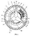
- FIG. 1 shows a mounted assembly comprising a tire 1 mounted and inflated on its mounting wheel 2 visible on the section along AA shown in FIG. 2 .
- the tire 1 comprises a tread 3 extended at its axial ends by sidewalls 4 , each sidewall ending at the mounting wheel 2 by parts 5 forming the beads of the tire (visible in FIG. 2 ) and intended for ensuring contact with said wheel, once the tire is mounted on its mounting wheel.
- a hubcap 6 is placed on the wheel and is held axially with respect to said wheel by conventional means, not shown, so as to be able to rotate freely around an axis which coincides with the axis of rotation XX 'of said wheel.
- This hubcap 6 comprises, at the periphery of a central part in the form of a disc 7 largely masking the wheel, a crown 8 connected to said central part 7 by three branches 9 , 10 , 11 .
- the crown 8 extends radially beyond the wheel and partly covers one of the sidewalls 4 of the tire.
- the crown 8 of the hubcap 6 is extended radially by three tabs 18 , 19 , 20 sliding in the radial direction (that is to say substantially perpendicular to the axis of rotation of the mounted assembly) relative to said crown and forming radial extensions which may extend to about half the height of one of the flanks.
- sidewall height is meant the radial distance between the end of the strip of axially outermost tire bearing and the sidewall part closest to the mounting wheel when the tire is mounted on said wheel.
- each pair of ribs delimits a space serving as housing 21 , 22 , 23 to a radial extension of the hubcap 6 .
- the three pairs of ribs are arranged on the side so that each pair is approximately 120 ° from the other two.
- the angular position of said hubcap is adjusted relative to the tire by rotating it to the desired position, then the hubcap is locked 6 in this position by sliding the sliding tabs 18 , 19 , 20 in the spaces 21 , 22 , 23 .
- means can be provided to block said legs in this position to prevent their radial displacement out of their housings.
- FIG. 1 We also distinguish in Figure 1 three windows 24, 25, 26 formed on the hubcap 6 and separating the disc 7 from the crown 8 of said hubcap; one of these windows is provided to allow access to an inflation valve of the tire. However, it is not essential to provide these windows, since it suffices to modify the inflation pressure of the tire to remove the hub cap in order to access the valve before replacing said hub cap in the correct position.
- FIG 2 there is shown the partial cross section along AA of the mounted assembly of Figure 1 (section containing the axis of rotation of the mounted assembly); in this schematic section, there is a branch 11 of the hubcap 6 extended radially by a sliding tab 18 which is inserted between the two ribs 16, 17 oriented substantially radially, said ribs cooperating with the tab 18 to prevent almost any relative movement of said hubcap relative to the tire 1 in the circumferential direction and so as to maintain the concordance of the decorative patterns produced on said hubcap and said tire.
- Each rib 16 , 17 can be produced by means of a series of small protuberances aligned in the same direction and molded on the surface of at least one side.
- a variant of the arrangement which has just been presented consists in making on at least a sidewall of the tire at least one groove (hollow) oriented in a direction substantially radial.
- substantially radial orientation is meant that the average orientation of the groove is such that its edges almost prevent any circumferential displacement of a radial extension of the hubcap, once this extension in place in the housing formed by said groove.
- each extension not being sliding radially with respect to said hubcap but capable of being housed in a housing provided on one sidewall of the tire when the hubcap is mounted on the bearing wheel the tire.
- the hubcap During rolling, the tire undergoing, in the part in contact with the ground, more or less significant bending deformations, it is preferable that the hubcap has flexibility characteristics suitable for easily following said deformations.
- a way to achieve this is to use a flexible material for the manufacture of the hubcap, such as for example, rubber.
- the hubcap being linked to the wheel in the axial direction, it cannot be ejected from the assembled assembly while driving.
- FIG. 3 Another variant of connection between a hubcap and a tire is shown in FIG. 3 .
- a schematic cross section of a mounted assembly composed of a tire mounted on a wheel (the cutting plane contains the axis of rotation of the mounted assembly).
- a hubcap 30 having a radial extension 31 in the form of a crown which extends to a sidewall 32 of a tire 33 and covers the entire part of said sidewall located between the mounting wheel 34 and the points of the sidewall located axially outermost of the tire.
- the extension 31 has an orifice forming a lumen 35 through which at least one rubber protuberance 36 molded (or glued) on the external surface of the sidewall 32 so as to allow a relative adjustment of the position of the hubcap 30 relative to said sidewall and to provide a mechanical connection forcing said hubcap to follow the tire in its possible rotational movements relative to its wheel 34 under the action of the forces exerted by the ground in the case of acceleration and / or braking as well as in the bending movements of the sidewall during the running of the mounted assembly fitted to a vehicle.
- the rubber protrusion 36 is only in contact with the walls. side of each orifice 35 of the cover (that is to say the walls spaced in the circumferential direction). In this way, the rubber protrusion 36 on the sidewall can move without any damage inside the orifice 35 under the effect of the crushing of the tire.
- FIG. 4 shows, in cross section, another variant assembly assembled according to the invention and according to which one of the sidewalls 41 of a tire 40 is provided with at least one rubber extension 44 extending towards the smaller spokes and covering at least partially the part of the wheel forming a wheel hook in contact with the tire.
- Each sidewall extension 44 cooperates with means provided on the hubcap 42 to ensure the correct positioning of the hubcap relative to the tire and to maintain said configuration during the use of the assembly mounted on a vehicle while driving.
- the mounting of such an assembly is done by first mounting the tire on its mounting wheel with each sidewall extension passing over the wheel hook; after inflation of the tire, the embellishment is then placed on the mounting wheel by lifting each sidewall extension 44 and then each of said extensions is inserted into a housing 45 provided on the hubcap.
- a unitary decorative pattern can be produced after assembly of the different parts (tire-wheel-hubcap) constituting the assembled assembly, since thus continuity is necessarily obtained and, in addition, the characteristics of the invention ensure the stability of this pattern during rolling.
Landscapes
- Engineering & Computer Science (AREA)
- Mechanical Engineering (AREA)
- Tires In General (AREA)
Applications Claiming Priority (2)
| Application Number | Priority Date | Filing Date | Title |
|---|---|---|---|
| FR9808112A FR2780344A1 (fr) | 1998-06-25 | 1998-06-25 | Ensemble monte pneumatique/roue comportant un enjoliveur |
| FR9808112 | 1998-06-25 |
Publications (2)
| Publication Number | Publication Date |
|---|---|
| EP0967094A1 EP0967094A1 (fr) | 1999-12-29 |
| EP0967094B1 true EP0967094B1 (fr) | 2003-03-12 |
Family
ID=9527892
Family Applications (1)
| Application Number | Title | Priority Date | Filing Date |
|---|---|---|---|
| EP99111413A Expired - Lifetime EP0967094B1 (fr) | 1998-06-25 | 1999-06-11 | Ensemble monté pneumatique/roue comportant un enjoliveur |
Country Status (5)
| Country | Link |
|---|---|
| US (1) | US6257675B1 (enExample) |
| EP (1) | EP0967094B1 (enExample) |
| JP (1) | JP4491088B2 (enExample) |
| DE (1) | DE69905800T2 (enExample) |
| FR (1) | FR2780344A1 (enExample) |
Cited By (1)
| Publication number | Priority date | Publication date | Assignee | Title |
|---|---|---|---|---|
| DE102007021168A1 (de) | 2007-05-05 | 2008-11-06 | Continental Aktiengesellschaft | Fahrzeugrad |
Families Citing this family (10)
| Publication number | Priority date | Publication date | Assignee | Title |
|---|---|---|---|---|
| US6454361B1 (en) * | 2001-04-30 | 2002-09-24 | Desmond G. Martin | Skateboard wheel cover rim |
| WO2004033230A2 (en) * | 2002-10-07 | 2004-04-22 | Tezzen Wheel Corporation | Wheel rim with extended outer flange |
| US6820669B2 (en) * | 2002-10-07 | 2004-11-23 | Tezzen Wheel Corporation | Wheel with extended outer flange |
| US7079042B2 (en) * | 2003-12-19 | 2006-07-18 | Michelin Recherche Et Technique S.A. | System for providing illuminated displays on a vehicle tire or wheel assembly |
| GB2421483A (en) * | 2004-12-21 | 2006-06-28 | Jaswant Panesar | Wheel rim protector |
| WO2008025026A2 (en) * | 2006-08-25 | 2008-02-28 | Brannon William W Iii | Aerodynamic wheel covering |
| DE102008046568A1 (de) * | 2008-09-05 | 2010-03-11 | Erlau Ag | Schutzvorrichtung für Flanken von Reifen von Fahrzeugen |
| AT508773B1 (de) * | 2010-04-29 | 2011-04-15 | Pewag Austria Gmbh | Reifen mit flankenschutz |
| MX2016001452A (es) * | 2013-07-30 | 2017-03-08 | Hutchinson Sa | Sistema de sujeción elastomérico para dispositivos con ruedas. |
| CN114919328B (zh) * | 2022-06-13 | 2025-06-13 | 安徽凯正汽车电子有限公司 | 一种适用于多种车型的轮毂盖及其使用方法 |
Family Cites Families (17)
| Publication number | Priority date | Publication date | Assignee | Title |
|---|---|---|---|---|
| US3128815A (en) * | 1964-04-14 | Sidewall and pneumatic tire combination | ||
| US1167124A (en) * | 1914-08-18 | 1916-01-04 | Thomas Sloper | Wind-shield. |
| US1448286A (en) * | 1922-10-25 | 1923-03-13 | Jackson D Comstock | Method of decorating automobile tire casings |
| US1753519A (en) * | 1928-08-15 | 1930-04-08 | Kanner Henry | Wheel and tire cover |
| US2548070A (en) * | 1948-11-22 | 1951-04-10 | Arthur M Ryan | Advertising display device |
| US2937903A (en) * | 1956-08-22 | 1960-05-24 | Gar Wood Ind Inc | Tire trim |
| US3050338A (en) * | 1957-09-09 | 1962-08-21 | Lyon Inc | Wheel cover |
| DE1079980B (de) * | 1957-11-25 | 1960-04-14 | F J Schoeps & Co G M B H | Fahrzeugrad, insbesondere fuer Kinderwagen |
| US2973992A (en) * | 1957-12-23 | 1961-03-07 | Lyon Inc | Wheel cover |
| US3012821A (en) * | 1958-02-19 | 1961-12-12 | Lyon Inc | Wheel cover |
| US2963326A (en) * | 1958-06-11 | 1960-12-06 | Charles B Aske Jr | Tire trim |
| WO1979000425A1 (en) * | 1977-12-23 | 1979-07-12 | Caterpillar Tractor Co | Tire sidewall protector for multi-piece rim wheels |
| US4317479A (en) * | 1980-08-19 | 1982-03-02 | The Firestone Tire & Rubber Company | Addition members for rubber articles |
| JPS6181201A (ja) * | 1984-09-27 | 1986-04-24 | Yutaka Matsushita | フリ−ホイ−ルキヤツプ |
| JPH0241901A (ja) * | 1988-08-01 | 1990-02-13 | Kanto Seiki Co Ltd | プラスチックホイールカバー |
| US5316376A (en) * | 1993-02-19 | 1994-05-31 | Defreitas Manuel P | Decorative wheel cover |
| US5490342A (en) * | 1994-07-13 | 1996-02-13 | Rutterman; Michael J. | Non-rotating wheel cover |
-
1998
- 1998-06-25 FR FR9808112A patent/FR2780344A1/fr active Pending
-
1999
- 1999-06-11 EP EP99111413A patent/EP0967094B1/fr not_active Expired - Lifetime
- 1999-06-11 DE DE69905800T patent/DE69905800T2/de not_active Expired - Lifetime
- 1999-06-16 US US09/334,516 patent/US6257675B1/en not_active Expired - Fee Related
- 1999-06-25 JP JP17915999A patent/JP4491088B2/ja not_active Expired - Fee Related
Cited By (1)
| Publication number | Priority date | Publication date | Assignee | Title |
|---|---|---|---|---|
| DE102007021168A1 (de) | 2007-05-05 | 2008-11-06 | Continental Aktiengesellschaft | Fahrzeugrad |
Also Published As
| Publication number | Publication date |
|---|---|
| US6257675B1 (en) | 2001-07-10 |
| FR2780344A1 (fr) | 1999-12-31 |
| EP0967094A1 (fr) | 1999-12-29 |
| JP4491088B2 (ja) | 2010-06-30 |
| DE69905800D1 (de) | 2003-04-17 |
| DE69905800T2 (de) | 2003-12-04 |
| JP2000025422A (ja) | 2000-01-25 |
Similar Documents
| Publication | Publication Date | Title |
|---|---|---|
| EP0967094B1 (fr) | Ensemble monté pneumatique/roue comportant un enjoliveur | |
| EP0300538B1 (fr) | Système pour la fixation positive à la jante d'une roue, pour un disque enjoliveur pour roue de véhicule industriel | |
| EP0748287B1 (fr) | Pneumatique avec des bourrelets de structure amelioree et ensemble d'un tel pneumatique avec une jante adaptee | |
| LU83690A1 (fr) | Ensemble jante et adaptateur de pneu | |
| FR2943274A1 (fr) | Pneumatique pourvu d'appliques colorees | |
| EP1289779B1 (fr) | Pneumatique comprenant un profile de renfort dans au moins un flanc et ensemble monte pneumatique/jante | |
| FR2609667A1 (fr) | Insert pour ensemble pneumatique-jante permettant de rouler a plat | |
| FR3093673A1 (fr) | Enjoliveur pour jantes de roue de véhicules automobiles | |
| EP4301610A1 (fr) | Insert de flanc pour pneumatique pour motocylcette | |
| FR2596708A1 (fr) | Roue de vehicule | |
| FR2722449A1 (fr) | Couvre-moyeu pour roues de vehicules automobile | |
| USD439875S1 (en) | Portion of a motorcycle rim | |
| EP1514703A1 (fr) | Méthode pour alléger un dispositif de roulage à plat de roue de véhicule automobile et dipositif ainsi obtenu | |
| FR2809348A1 (fr) | Pneumatique comprenant un profile de renfort dans au moins un flanc et ensemble pneumatique/jante comprenant un tel pneumatique | |
| FR3067285A1 (fr) | Roue de montage pour vehicule automobile et ensemble monte comportant une telle roue de montage | |
| JP3137479U (ja) | 車両用ホイール | |
| FR2842140A1 (fr) | Ensemble monte tubeless pour cycle, jante et pneumatique tubeless | |
| EP1838540B1 (fr) | Pneumatique dont au moins un siege de bourrelet comporte une nervure | |
| EP4351891B1 (fr) | Extenseur à stylisme perfectionné et ensemble roulant comportant un tel extenseur | |
| EP3074246A1 (fr) | Pneumatique comportant un motif de masquage de defaut sur un flanc | |
| WO2016151210A1 (fr) | Enjoliveur de roue de véhicule automobile comportant des bourrelets de protection en plastique souple | |
| EP2595819A1 (fr) | Enjoliveur pour une roue d'un vehicule comportant un anneau circulaire et procede de montage ou de demontage de cet anneau sur l'enjoliveur | |
| WO2008129169A1 (fr) | Pneumatique pour cycle et jante adaptée à ce pneumatique, ainsi qu'une roue de cycle les comportant | |
| EP1438771A1 (fr) | Contacteur electrique tournant et ensemble de direction de vehicule automobile muni de ce contacteur | |
| FR2838674A1 (fr) | Enjoliveur de roue de vehicule automobile comportant une trappe d'acces a une valve de gonflage |
Legal Events
| Date | Code | Title | Description |
|---|---|---|---|
| PUAI | Public reference made under article 153(3) epc to a published international application that has entered the european phase |
Free format text: ORIGINAL CODE: 0009012 |
|
| AK | Designated contracting states |
Kind code of ref document: A1 Designated state(s): DE FR GB IT |
|
| AX | Request for extension of the european patent |
Free format text: AL;LT;LV;MK;RO;SI |
|
| 17P | Request for examination filed |
Effective date: 20000629 |
|
| AKX | Designation fees paid |
Free format text: DE FR GB IT |
|
| GRAG | Despatch of communication of intention to grant |
Free format text: ORIGINAL CODE: EPIDOS AGRA |
|
| 17Q | First examination report despatched |
Effective date: 20020513 |
|
| GRAG | Despatch of communication of intention to grant |
Free format text: ORIGINAL CODE: EPIDOS AGRA |
|
| GRAH | Despatch of communication of intention to grant a patent |
Free format text: ORIGINAL CODE: EPIDOS IGRA |
|
| GRAH | Despatch of communication of intention to grant a patent |
Free format text: ORIGINAL CODE: EPIDOS IGRA |
|
| GRAA | (expected) grant |
Free format text: ORIGINAL CODE: 0009210 |
|
| AK | Designated contracting states |
Designated state(s): DE FR GB IT |
|
| PG25 | Lapsed in a contracting state [announced via postgrant information from national office to epo] |
Ref country code: IT Free format text: LAPSE BECAUSE OF FAILURE TO SUBMIT A TRANSLATION OF THE DESCRIPTION OR TO PAY THE FEE WITHIN THE PRESCRIBED TIME-LIMIT;WARNING: LAPSES OF ITALIAN PATENTS WITH EFFECTIVE DATE BEFORE 2007 MAY HAVE OCCURRED AT ANY TIME BEFORE 2007. THE CORRECT EFFECTIVE DATE MAY BE DIFFERENT FROM THE ONE RECORDED. Effective date: 20030312 |
|
| REG | Reference to a national code |
Ref country code: GB Ref legal event code: FG4D Free format text: NOT ENGLISH |
|
| REF | Corresponds to: |
Ref document number: 69905800 Country of ref document: DE Date of ref document: 20030417 Kind code of ref document: P |
|
| GBT | Gb: translation of ep patent filed (gb section 77(6)(a)/1977) | ||
| PLBE | No opposition filed within time limit |
Free format text: ORIGINAL CODE: 0009261 |
|
| STAA | Information on the status of an ep patent application or granted ep patent |
Free format text: STATUS: NO OPPOSITION FILED WITHIN TIME LIMIT |
|
| 26N | No opposition filed |
Effective date: 20031215 |
|
| PGFP | Annual fee paid to national office [announced via postgrant information from national office to epo] |
Ref country code: GB Payment date: 20080620 Year of fee payment: 10 |
|
| GBPC | Gb: european patent ceased through non-payment of renewal fee |
Effective date: 20090611 |
|
| PG25 | Lapsed in a contracting state [announced via postgrant information from national office to epo] |
Ref country code: GB Free format text: LAPSE BECAUSE OF NON-PAYMENT OF DUE FEES Effective date: 20090611 |
|
| PGFP | Annual fee paid to national office [announced via postgrant information from national office to epo] |
Ref country code: DE Payment date: 20120622 Year of fee payment: 14 |
|
| PGFP | Annual fee paid to national office [announced via postgrant information from national office to epo] |
Ref country code: FR Payment date: 20120705 Year of fee payment: 14 |
|
| REG | Reference to a national code |
Ref country code: DE Ref legal event code: R119 Ref document number: 69905800 Country of ref document: DE Effective date: 20140101 |
|
| REG | Reference to a national code |
Ref country code: FR Ref legal event code: ST Effective date: 20140228 |
|
| PG25 | Lapsed in a contracting state [announced via postgrant information from national office to epo] |
Ref country code: DE Free format text: LAPSE BECAUSE OF NON-PAYMENT OF DUE FEES Effective date: 20140101 |
|
| PG25 | Lapsed in a contracting state [announced via postgrant information from national office to epo] |
Ref country code: FR Free format text: LAPSE BECAUSE OF NON-PAYMENT OF DUE FEES Effective date: 20130701 |