EP0967039B1 - Schneidwerkzeughalter - Google Patents
Schneidwerkzeughalter Download PDFInfo
- Publication number
- EP0967039B1 EP0967039B1 EP99108052A EP99108052A EP0967039B1 EP 0967039 B1 EP0967039 B1 EP 0967039B1 EP 99108052 A EP99108052 A EP 99108052A EP 99108052 A EP99108052 A EP 99108052A EP 0967039 B1 EP0967039 B1 EP 0967039B1
- Authority
- EP
- European Patent Office
- Prior art keywords
- passage
- tool
- piston
- house
- male member
- Prior art date
- Legal status (The legal status is an assumption and is not a legal conclusion. Google has not performed a legal analysis and makes no representation as to the accuracy of the status listed.)
- Expired - Lifetime
Links
- 230000007246 mechanism Effects 0.000 claims abstract description 10
- 239000003921 oil Substances 0.000 description 6
- 230000001464 adherent effect Effects 0.000 description 3
- 238000007789 sealing Methods 0.000 description 3
- 230000008901 benefit Effects 0.000 description 2
- 230000008859 change Effects 0.000 description 2
- 238000013459 approach Methods 0.000 description 1
- 230000008878 coupling Effects 0.000 description 1
- 238000010168 coupling process Methods 0.000 description 1
- 238000005859 coupling reaction Methods 0.000 description 1
- 230000001419 dependent effect Effects 0.000 description 1
- 238000005553 drilling Methods 0.000 description 1
- 239000010720 hydraulic oil Substances 0.000 description 1
- 239000007788 liquid Substances 0.000 description 1
- 239000002184 metal Substances 0.000 description 1
- 238000003801 milling Methods 0.000 description 1
- 230000004048 modification Effects 0.000 description 1
- 238000012986 modification Methods 0.000 description 1
- 230000007704 transition Effects 0.000 description 1
- 238000007514 turning Methods 0.000 description 1
Images

Classifications
-
- B—PERFORMING OPERATIONS; TRANSPORTING
- B23—MACHINE TOOLS; METAL-WORKING NOT OTHERWISE PROVIDED FOR
- B23B—TURNING; BORING
- B23B29/00—Holders for non-rotary cutting tools; Boring bars or boring heads; Accessories for tool holders
- B23B29/04—Tool holders for a single cutting tool
- B23B29/046—Tool holders for a single cutting tool with an intermediary toolholder
-
- B—PERFORMING OPERATIONS; TRANSPORTING
- B23—MACHINE TOOLS; METAL-WORKING NOT OTHERWISE PROVIDED FOR
- B23B—TURNING; BORING
- B23B31/00—Chucks; Expansion mandrels; Adaptations thereof for remote control
- B23B31/02—Chucks
- B23B31/24—Chucks characterised by features relating primarily to remote control of the gripping means
- B23B31/26—Chucks characterised by features relating primarily to remote control of the gripping means using mechanical transmission through the working-spindle
- B23B31/261—Chucks characterised by features relating primarily to remote control of the gripping means using mechanical transmission through the working-spindle clamping the end of the toolholder shank
-
- Y—GENERAL TAGGING OF NEW TECHNOLOGICAL DEVELOPMENTS; GENERAL TAGGING OF CROSS-SECTIONAL TECHNOLOGIES SPANNING OVER SEVERAL SECTIONS OF THE IPC; TECHNICAL SUBJECTS COVERED BY FORMER USPC CROSS-REFERENCE ART COLLECTIONS [XRACs] AND DIGESTS
- Y10—TECHNICAL SUBJECTS COVERED BY FORMER USPC
- Y10T—TECHNICAL SUBJECTS COVERED BY FORMER US CLASSIFICATION
- Y10T408/00—Cutting by use of rotating axially moving tool
- Y10T408/94—Tool-support
- Y10T408/95—Tool-support with tool-retaining means
-
- Y—GENERAL TAGGING OF NEW TECHNOLOGICAL DEVELOPMENTS; GENERAL TAGGING OF CROSS-SECTIONAL TECHNOLOGIES SPANNING OVER SEVERAL SECTIONS OF THE IPC; TECHNICAL SUBJECTS COVERED BY FORMER USPC CROSS-REFERENCE ART COLLECTIONS [XRACs] AND DIGESTS
- Y10—TECHNICAL SUBJECTS COVERED BY FORMER USPC
- Y10T—TECHNICAL SUBJECTS COVERED BY FORMER US CLASSIFICATION
- Y10T409/00—Gear cutting, milling, or planing
- Y10T409/30—Milling
- Y10T409/309352—Cutter spindle or spindle support
- Y10T409/309408—Cutter spindle or spindle support with cutter holder
- Y10T409/309464—Cutter spindle or spindle support with cutter holder and draw bar
-
- Y—GENERAL TAGGING OF NEW TECHNOLOGICAL DEVELOPMENTS; GENERAL TAGGING OF CROSS-SECTIONAL TECHNOLOGIES SPANNING OVER SEVERAL SECTIONS OF THE IPC; TECHNICAL SUBJECTS COVERED BY FORMER USPC CROSS-REFERENCE ART COLLECTIONS [XRACs] AND DIGESTS
- Y10—TECHNICAL SUBJECTS COVERED BY FORMER USPC
- Y10T—TECHNICAL SUBJECTS COVERED BY FORMER US CLASSIFICATION
- Y10T82/00—Turning
- Y10T82/25—Lathe
- Y10T82/2585—Tool rest
- Y10T82/2589—Quick release tool or holder clamp
Definitions
- This invention relates to a holder adapted for detachable mounting of cutting tools, said holder comprising a house having a first end to which a tool is adapted to be detachably mounted and a clamping mechanism provided in said house, said clamping mechanism including a male member adapted to engage in a female-like opening in the tool, said male member being movable to and fro between an inner end position, where the tool is clamped relative to the house, and an outer end position, where the tool is releasable from the house, more precisely by means of a piston device that is movable to and fro in a cavity within the house, said piston device separating outer and inner chambers to and from which a hydraulic medium may be fed in order to move said male member towards one of said end positions, the piston device comprising a spigot, that extends from a piston of the piston device and is adapted to contact and move relative to the male member to cause the male member to move between the inner end and outer end positions.
- Tool holders of the kind defined above are frequently present in automatic machines for metal cutting, i.e. turning, milling, drilling and the like.
- a benefit with this type of holder is that it allows quick and simple tool exchanges.
- a problem in connection with previously known tool holders is the adjustment of the pressure of the hydraulic medium, usually oil, that is fed into one of the chambers of the house in order to either clamp the tool or push out the same.
- the adjustment of the pressure is especially tricky as regards the hydraulic medium that is fed into the outer chamber in connection with clamping of the tool. If the tool is clamped by an excessively large force the components included in the clamping mechanism may be damaged or at least, in the long run, be worn out too quickly. Therefore, it is desirable to limit the pressure of the hydraulic medium that is fed to the outer chamber to a maximum value.
- a theoretically feasible solution of the problem mentioned above would be to provide an external pressure adjusting system in the hydraulic system of the automatic machine itself, i.e. to provide, in one way or another, a fine adjustment of the pressures to both of the hydraulic medium chambers of the tool holder.
- this is for several reasons no attractive problem solution. Since the pressure adjustment in such a case would take place at a distance from the tool holder, unavoidable pressure variations in the hydraulic system as a whole (as a consequence of the fact that other functions in the machine is activated or inactivated) may lead to the consequence that the outer chamber will not safely operate with a certain maximum pressure. Further, a remote controlled pressure adjusting system would run a risk that individual operators could too easily change the working pressures in the respective chambers in an uncontrolled way that is not always desired.
- a primary object of the invention is to provide a tool holder that independently of any pressure variations being present in the hydraulic system as a whole, always guarantees that the hydraulic pressure in the outer chamber is maximised to an upper limit value.
- a further object is to provide a tool holder in which the adjustment of the hydraulic pressure calls for certain measures, more precisely in order to eliminate the risk that individual operators change the pressure in an uncontrolled manner.
- Still a further object of the invention is to provide a tool holder that realizes the desired pressure adjusting function via structurally simple and cheap means.
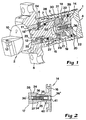
- reference numeral 1 generally designates a tool holder in which a tool, designated 2, may be detachably mounted.
- the holder 1 is in the shape of a cylindrical house that on one hand is composed of a rear part constituting a cylindrical tube 3 and an end wall 4, and on the other hand of a front part comprising a flange 5 and a tube socket 6 extending rearwardly from the flange 5, said tube socket 6 being connected with the cylindrical tube 3 via a thread coupling 7.
- a central hole 9 is recessed, said hole 9 serving as grip for the tool 2.
- the tool 2 comprises a part 11 in the shape of a short tube piece, said part 11 extending rearwardly from the head 10 and defining a female-like opening 12 that emerges rearwardly.
- the external envelope surface of the tube piece 11, as well as the internal surface of the hole 9, may have a polygonal cross sectional shape and an axially tapering shape.
- Such tools are commercially available under the trade name COROMANT CAPTOTM.
- the tool 2 is equipped with at least one cutting insert 13.
- the piston device 14 includes, on one hand, an actual piston 16 and, on the other hand, a spigot 17 projecting from one side of the piston 16.
- the piston 16 divides a cavity 18 within the house into a frontal or outer chamber 19, on one hand, and a rear or inner chamber 20, on the other hand. Oil or another suitable hydraulic medium may be fed into respectively out of said chambers via first and second passages 21 and 22 respectively.
- the male member 15 has a rotationally symmetrical shape and engages a number of tangentially separated fingers 23 that are mounted in a ring 24 and may, with their thickened outer portions, engage in a groove 25 at the inner side of the tube piece 11.
- the male member is sealed, via a sealing ring 27, against a sleeve 26 provided in the house.
- the outer chamber 19 is defined between, on one hand, said sealing ring 27 and, on the other hand, an analogous sealing ring 28 at the periphery of the piston 16.
- the sleeve 26 has a conical, rearwardly widening surface 29 against which conical surfaces 30 partially abut, said surfaces 30 being provided at tangentially separated driving bodies 31.
- Rear, planar end surfaces of these driving bodies abut a ring 32 included in the male member 15.
- Internal conical surfaces 33 of the bodies 31 abut a conical surface 34 on the spigot 17 of the piston device, said conical surface 34 converging in a rearward direction.
- the spigot 17 has a waist portion 35 of reduced diameter.
- a second conical surface 34' having an essentially larger cone angle than the conical surface 34.
- the male member 15, the fingers 23, the driving bodies 31 and the spigot 17 together form the main components of a clamping mechanism by means of which the tool 2 may be either clamped in the house of the tool holder or released therefrom. More precisely, the clamping is effected in the state shown in the lower half of figure 3. In this state the piston device has been displaced, by feeding of hydraulic oil to the outer chamber 19, to an inner end position in which the conical surfaces 34 and 34' have drawn the driving bodies 31 and urged them outwards to radially outer end positions. At the same time as the bodies 31 move axially rearwards, the ring 32 is driven and thus the entire male member 15.
- Oil is fed into the inner chamber 20 via the passage 22 (simultaneously as the oil from the chamber 19 returns to the reservoir via the passage 21) when the tool is to be released and pushed out of the holder.
- the male member will be moved to an outer end position (as shown in the upper half of figure 3), more precisely by abutting the free end surface of the piston spigot 17 against an analogous rear end surface of the male member.
- the ring 32 drives the driving bodies 31 in the axial direction and the conical surfaces 29, 30 effectuate a movement of said bodies also in the radial direction, more precisely in a direction towards the centre.
- a passage 36 extends through the piston device 14 and includes a valve having the function to open the passage when the hydraulic pressure in the outer chamber 19 increases to a set limit value.
- the valve is constituted by a ball 37 that is loaded by a pressure spring 38, e.g. a helical pressure spring. The ball abuts a seat 39 that is provided in the transition between a narrow, outer passage section 36' and a wider passage section 36''.
- the valve constitutes a pressure restriction valve with a check valve function.
- the spring 38 cooperates with means for adjustable setting of the spring force thereof.
- figure 2 shows how the rear or inner end of the spring 38 abuts an externally threaded sleeve 40 that is in engagement with an internal thread 41 in the passage 36.
- the sleeve 40 has a groove for a driver that may be inserted into the passage in order to bring the sleeve to rotate and hence be displaced axially in either direction in order to alternatively increase or decrease the spring force.
- the ball 37 serving as valve body, is urged against the associated seat with a force that will be overcome when the hydraulic pressure in the chamber 19 reaches the desired value.
- the piston device in this case includes not only the spigot 17 projecting ahead of the piston 16, but also a spigot 17' projecting in a rearward direction relative to the piston.
- Said spigot 17' extends through a through-going hole 42 in the end wall 4' of the cylindrical house.
- the free, projecting end of the spigot 17' is thus located outside of the house of the holder, and thereby the spigot may be coupled to a measuring device or a sensing device by means of which it can be determined whether the male member of the clamping mechanism is in its outer or inner end position.
- the central oil passage 36 is divided into one or more radial passages 43 that emerge in the envelope surface of the rear spigot 17', preferably close to the piston 16.
- the piston 16 In its inner end position, shown in figure 4, the piston 16 abuts an annular abutment surface 44, inside of which a recess 45 is provided in the end wall 4'.
- the branch passages 43 are located in such a way that they emerge in this recess when the piston device assumes its inner end position.
- the oil passage 22 is L-shaped and provided in the end wall 4' itself.
- the ball 37 serving as a valve body, is, in this embodiment, located between the spring 38 and the sleeve 40, a seat for the ball being provided in the sleeve itself. Also in this case the adjustment of the spring force is effected by screwing of the sleeve 40, although said sleeve 40 abuts the ball that in its turn abuts the spring.
- valve spring 38 works with a force that is set once and for all.
- the spring and the ball 37 are secured in the adherent passage by means of an elastic washer 46 that is fixed by snapping against an abutment shoulder in a rear end portion of the passage.
- a basic advantage of the tool holder according to the invention is that the pressure adjustment, more precisely the determination of a maximum pressure present in the outer hydraulic chamber, takes place within the tool holder itself and not by means of adjusting devices that are spaced from the tool holder. Among other things, this means that sufficient pressure adjustment may be effected in an exact way without depending on possible pressure variations in the hydraulic system as a whole. Furthermore, the risk of non-authorised adjustments of the working pressure of the tool holder is eliminated.
- the invention is not limited to the embodiments described and shown in the drawings only. Although it is preferred to locate the overflow passage between the two hydraulic chambers centrally in the piston device, it is thus also possible to locate the passage and the adherent check valve in a non-centric position in the piston device.
- the passage must not necessarily extend axially through the piston device. Thus, it is only essential that the passage extends through the spigot and at its opposite ends emerges in the respective chambers and allows liquid flow between said chambers when the valve is opened.
- a spring-loaded ball is exemplified in the drawings also other, arbitrary valve designs are feasible.
- the valve body may for instance be in the shape of a cone.
- the invention is neither limited to the type of tool holder that is marketed under the trade name COROMANT CAPTOTM, but may be used in connection with any tool holders of the type defined in appended claim 1.
Landscapes
- Engineering & Computer Science (AREA)
- Mechanical Engineering (AREA)
- Gripping On Spindles (AREA)
- Cutting Tools, Boring Holders, And Turrets (AREA)
- Auxiliary Devices For Machine Tools (AREA)
- Polishing Bodies And Polishing Tools (AREA)
Claims (7)
- Halter für das lösbare Anbringen von Schneidwerkzeugen, mit einem Gehäuse mit einem ersten Ende, an welchem ein Werkzeug lösbar befestigt werden kann, und einem in dem Gehäuse vorgesehenen Klemmechanismus, der ein Einsteckteil (15) aufweist, welches geeignet ist, in einer aufnahmeartigen Öffnung (12) in dem Werkzeug (2) in Eingriff zu kommen, wobei das Einsteckteil (15) zwischen einer inneren Endposition, in welcher das Werkzeug relativ zu dem Gehäuse eingeklemmt ist, und einer äußeren Endposition, in welcher das Werkzeug von dem Gehäuse lösbar ist, bewegbar ist, wobei das Einsteckteil (15) durch eine Kolbenvorrichtung (14) bewegbar ist, die in einem Hohlraum (18) innerhalb des Gehäuses bewegbar ist, wobei die Kolbenvorrichtung (14) äußere und innere Kammern (19, 20) trennt, zu denen ein hydraulisches Medium zugeführt und aus denen es herausgeführt werden kann, um das Einsteckteil zu der Position des inneren Endes hin oder zu der Position des äußeren Endes hin zu bewegen, wobei die Kolbenvorrichtung (14) einen Leitungshahn (17) aufweist, welcher sich von einem Kolben (16) der Kolbenvorrichtung (14) erstreckt und geeignet ist, sich relativ zu dem Einsteckteil (15) zu bewegen und dies zu berühren, um das Einsteckteil zu veranlassen, sich zwischen der Position des inneren Endes und der des äußeren Endes zu bewegen, dadurch gekennzeichnet, daß sich ein Durchgang (36) durch den Kolben (16) und den Leitungshahn (17) erstreckt, der Durchgang (36) in den zwei Kammern (19; 20) entsteht, ein Ventil (37) in dem Durchgang (36) vorgesehen ist, um den Durchgang zu öffnen, wenn der Hydraulikdruck in der äußeren Kammer (19) auf einen eingestellten Grenzwert ansteigt, um den hydraulischen Druck für das Festklemmen des Werkzeuges zu begrenzen.
- Halter nach Anspruch 1, dadurch gekennzeichnet, daß das Ventil in einer bekannten Weise einen kugelförmigen oder konusförmigen Ventilkörper (37) aufweist, der von einer Druckfeder (38) belastet ist.
- Halter nach Anspruch 2, dadurch gekennzeichnet, daß die Feder (38) mit Mitteln (40) für das einstellbare Festsetzen seiner Federkraft zusammenwirkt.
- Halter nach Anspruch 3, dadurch gekennzeichnet, daß das Mittel von einer Hülse (40) mit Außengewinde gebildet ist, welche mit einem Innengewinde (41) in dem Durchgang (36) in Eingriff tritt.
- Halter nach Anspruch 4, dadurch gekennzeichnet, daß der Ventilkörper (37) zwischen der Feder (38) und der Hülse (40), die einen Sitz für den Ventilkörper hat, vorgesehen ist.
- Halter nach einem der vorhergehenden Ansprüche, dadurch gekennzeichnet, daß sich der Durchgang (36) axial und mittig durch die Kolbenvorrichtung erstreckt.
- Halter nach Anspruch 5 oder 6, dadurch gekennzeichnet, daß die Kolbenvorrichtung, abgesehen von einem vorliegenden Kolben (16), zwei Leitungshähne (17, 17') aufweist, die sich von entgegengesetzten Seiten des Kolbens (16) axial erstrecken, wobei ein erster der Leitungshähne (17) in der äußeren Kammer (19) für Hydraulikmedium angeordnet und so ausgestaltet ist, daß er mit dem Klemmechanismus zusammenwirkt, während ein zweiter Leitungshahn (17') von außerhalb des Gehäuses dadurch zugänglich ist, daß er durch ein Loch (42) in einer Hinterendwand (4') des Gehäuses hindurchragt, dadurch gekennzeichnet, daß der Mitteldurchgang (36) sich in einen oder mehrere radiale Durchgänge (43) teilt, die im hinteren Leitungshahn (17') in einem Bereich hinter dem vorliegenden Kolben (16) auftreten.
Applications Claiming Priority (2)
| Application Number | Priority Date | Filing Date | Title |
|---|---|---|---|
| SE9802243A SE512241C2 (sv) | 1998-06-24 | 1998-06-24 | Hållare för lösgörbar montering av skärverktyg |
| SE9802243 | 1998-06-24 |
Publications (3)
| Publication Number | Publication Date |
|---|---|
| EP0967039A2 EP0967039A2 (de) | 1999-12-29 |
| EP0967039A3 EP0967039A3 (de) | 2002-11-13 |
| EP0967039B1 true EP0967039B1 (de) | 2005-04-13 |
Family
ID=20411820
Family Applications (1)
| Application Number | Title | Priority Date | Filing Date |
|---|---|---|---|
| EP99108052A Expired - Lifetime EP0967039B1 (de) | 1998-06-24 | 1999-04-23 | Schneidwerkzeughalter |
Country Status (6)
| Country | Link |
|---|---|
| US (1) | US6193451B1 (de) |
| EP (1) | EP0967039B1 (de) |
| JP (1) | JP2000005905A (de) |
| AT (1) | ATE293021T1 (de) |
| DE (1) | DE69924671T2 (de) |
| SE (1) | SE512241C2 (de) |
Families Citing this family (8)
| Publication number | Priority date | Publication date | Assignee | Title |
|---|---|---|---|---|
| SE514356C2 (sv) * | 1999-06-09 | 2001-02-12 | Sandvik Ab | Hållare för lösgörbar montering av skärverktyg |
| DE10043006C1 (de) * | 2000-09-01 | 2002-04-18 | Ott Jakob Spanntech Gmbh & Co | Betätigungsvorrichtung für einen Werkzeug- oder Werkstückspanner in einer Werkzeugmaschinenspindel |
| TW566264U (en) * | 2001-11-28 | 2003-12-11 | Ind Tech Res Inst | Tool releasing mechanism used in vertical coupling type spindle of machine tool |
| JP2004066440A (ja) * | 2002-08-09 | 2004-03-04 | Mori Seiki Co Ltd | 工作機械の主軸ユニット |
| FI20050916A0 (fi) * | 2005-09-14 | 2005-09-14 | Mandrel Oy | Järjestely lastuavassa työkalussa |
| EP1947372A1 (de) * | 2007-01-18 | 2008-07-23 | Kongsberg Automotive AS | Schaltsystem mit Antriebshilfssystem |
| JP5406579B2 (ja) * | 2009-03-31 | 2014-02-05 | ヤマザキマザック株式会社 | 縦型タレット旋盤 |
| SE537043C2 (sv) * | 2013-04-11 | 2014-12-16 | Sandvik Intellectual Property | Första kopplingsdel och verktygskoppling |
Family Cites Families (18)
| Publication number | Priority date | Publication date | Assignee | Title |
|---|---|---|---|---|
| US3842712A (en) * | 1971-07-28 | 1974-10-22 | Ex Cell O Corp | Machine tool with automatic tool changing means |
| US4008646A (en) * | 1974-08-30 | 1977-02-22 | Textron, Inc. | Machine tools |
| EP0051701A1 (de) * | 1980-11-06 | 1982-05-19 | The Jacobs Manufacturing Company | Bremsvorrichtung für eine Brennkraftmaschine |
| US4398326A (en) * | 1981-07-01 | 1983-08-16 | Kearney & Trecker Corporation | Collet unclamping mechanism |
| US4583894A (en) * | 1984-07-02 | 1986-04-22 | Ex-Cell-O Corporation | High speed motorized spindle with tool clamping/unclamping mechanism |
| JPS60215109A (ja) * | 1985-02-22 | 1985-10-28 | Kitagawa Tekkosho:Kk | 安全機構を有する回転流体圧シリンダ |
| DE8513540U1 (de) * | 1985-05-08 | 1985-06-27 | Paul Forkardt GmbH & Co KG, 4000 Düsseldorf | Vorrichtung zum Festspannen von Werkzeugen an einem Werkzeugträger einer Werkzeugmaschine |
| DE3617103C1 (de) * | 1986-05-21 | 1987-08-27 | Fortuna Werke Maschf Ag | Mit einer Werkzeugspanneinrichtung versehene Spindel einer Werkzeugmaschine |
| DE3619071A1 (de) * | 1986-06-06 | 1987-12-10 | Heller Geb Gmbh Maschf | Bearbeitungsmaschine mit einem schwenkkopf |
| US4930553A (en) * | 1989-01-23 | 1990-06-05 | The Lee Company | Pressure relief valve |
| US5096347A (en) * | 1990-04-20 | 1992-03-17 | Mori Seiko Co., Ltd. | Spring clamp with clamped condition holding device |
| DE4120360A1 (de) * | 1991-06-20 | 1992-12-24 | Zahnradfabrik Friedrichshafen | Stromregelventil |
| US5193954A (en) * | 1991-10-30 | 1993-03-16 | Gte Valenite Corporation | Universal tool connection |
| US5466102A (en) * | 1993-12-16 | 1995-11-14 | Kennametal Inc. | System for coupling machine tools |
| JPH08281504A (ja) * | 1995-04-14 | 1996-10-29 | Okuma Mach Works Ltd | 工具クランプのかけ外し機構 |
| US5626325A (en) * | 1995-09-14 | 1997-05-06 | Cummins Engine Company, Inc. | High pressure control valve for a fuel injection system |
| DE19543612C1 (de) * | 1995-11-23 | 1997-05-07 | Glyco Antriebstechnik Gmbh | Spannvorrichtung mit integrierter Fluid-Drehdurchführung |
| DE19548711A1 (de) * | 1995-12-23 | 1997-07-03 | Klement Klaus Dieter | Schnittstelle zwischen einem Werkzeugträger und einem Spannschaft einer Werkzeugmaschine |
-
1998
- 1998-06-24 SE SE9802243A patent/SE512241C2/sv not_active IP Right Cessation
-
1999
- 1999-04-23 DE DE69924671T patent/DE69924671T2/de not_active Expired - Fee Related
- 1999-04-23 AT AT99108052T patent/ATE293021T1/de not_active IP Right Cessation
- 1999-04-23 EP EP99108052A patent/EP0967039B1/de not_active Expired - Lifetime
- 1999-05-20 JP JP11140137A patent/JP2000005905A/ja active Pending
- 1999-06-07 US US09/326,677 patent/US6193451B1/en not_active Expired - Fee Related
Also Published As
| Publication number | Publication date |
|---|---|
| DE69924671T2 (de) | 2006-03-02 |
| EP0967039A2 (de) | 1999-12-29 |
| SE512241C2 (sv) | 2000-02-14 |
| EP0967039A3 (de) | 2002-11-13 |
| US6193451B1 (en) | 2001-02-27 |
| DE69924671D1 (de) | 2005-05-19 |
| SE9802243L (sv) | 1999-12-25 |
| JP2000005905A (ja) | 2000-01-11 |
| ATE293021T1 (de) | 2005-04-15 |
| SE9802243D0 (sv) | 1998-06-24 |
Similar Documents
| Publication | Publication Date | Title |
|---|---|---|
| US4549846A (en) | Automatic hand changing device for industrial robots | |
| US4632614A (en) | Composite tool unit for chip-removing machining | |
| US4915553A (en) | Tool retention and ejection mechanism | |
| KR101145449B1 (ko) | 절삭 공구 및 절삭 공구 조립 방법 | |
| CA1170867A (en) | Chuck | |
| US4813829A (en) | Tooling apparatus comprising a holder and tool head releasably mounted thereon | |
| EP0967039B1 (de) | Schneidwerkzeughalter | |
| EP1060819B1 (de) | Halter für lösbare Verbindung von Schneidwerkzeugen | |
| US4958968A (en) | Adapter for machine-tool spindle | |
| US6485214B2 (en) | Coupling device | |
| GB2154481A (en) | Machine tool spindle and tool holder suitable therefor | |
| US6257595B1 (en) | Collect chuck with quick-change cap | |
| US4976575A (en) | Tool holding system for automatic tool changing | |
| US6219893B1 (en) | Coupling for clamping a pallet | |
| EP0625932B1 (de) | Kugelverriegelvorrichtung mit kugel ohne kugelhalter | |
| US6908085B2 (en) | Rotating tool chucking device | |
| EP0960676A1 (de) | Werkzeug und Spanner für spannabhebende Arbeitung | |
| US5957639A (en) | Hollow cone device for gripping attachments | |
| US4334811A (en) | Spindle extension, especially for drilling and milling machines | |
| CA2466774C (en) | A milling tool holder with differential screw | |
| US5037254A (en) | Tool clamping device | |
| US4580472A (en) | Cutting tool with interchangeable tool head for machine tools | |
| US7244080B2 (en) | Quick-change insert for tools, especially for thread drills | |
| GB2159736A (en) | Clamping device for tools, such as drills, milling cutters or the like | |
| US5716053A (en) | Sealing plug for machine tools |
Legal Events
| Date | Code | Title | Description |
|---|---|---|---|
| PUAI | Public reference made under article 153(3) epc to a published international application that has entered the european phase |
Free format text: ORIGINAL CODE: 0009012 |
|
| AK | Designated contracting states |
Kind code of ref document: A2 Designated state(s): AT BE CH CY DE DK ES FI FR GB GR IE IT LI LU MC NL PT SE |
|
| AX | Request for extension of the european patent |
Free format text: AL;LT;LV;MK;RO;SI |
|
| PUAL | Search report despatched |
Free format text: ORIGINAL CODE: 0009013 |
|
| AK | Designated contracting states |
Kind code of ref document: A3 Designated state(s): AT BE CH CY DE DK ES FI FR GB GR IE IT LI LU MC NL PT SE |
|
| AX | Request for extension of the european patent |
Free format text: AL;LT;LV;MK;RO;SI |
|
| 17P | Request for examination filed |
Effective date: 20030430 |
|
| AKX | Designation fees paid |
Designated state(s): AT BE CH CY DE DK ES FI FR GB GR IE IT LI LU MC NL PT SE |
|
| 17Q | First examination report despatched |
Effective date: 20031217 |
|
| GRAP | Despatch of communication of intention to grant a patent |
Free format text: ORIGINAL CODE: EPIDOSNIGR1 |
|
| GRAS | Grant fee paid |
Free format text: ORIGINAL CODE: EPIDOSNIGR3 |
|
| GRAA | (expected) grant |
Free format text: ORIGINAL CODE: 0009210 |
|
| AK | Designated contracting states |
Kind code of ref document: B1 Designated state(s): AT BE CH CY DE DK ES FI FR GB GR IE IT LI LU MC NL PT SE |
|
| PG25 | Lapsed in a contracting state [announced via postgrant information from national office to epo] |
Ref country code: NL Free format text: LAPSE BECAUSE OF FAILURE TO SUBMIT A TRANSLATION OF THE DESCRIPTION OR TO PAY THE FEE WITHIN THE PRESCRIBED TIME-LIMIT Effective date: 20050413 Ref country code: LI Free format text: LAPSE BECAUSE OF FAILURE TO SUBMIT A TRANSLATION OF THE DESCRIPTION OR TO PAY THE FEE WITHIN THE PRESCRIBED TIME-LIMIT Effective date: 20050413 Ref country code: IT Free format text: LAPSE BECAUSE OF FAILURE TO SUBMIT A TRANSLATION OF THE DESCRIPTION OR TO PAY THE FEE WITHIN THE PRESCRIBED TIME-LIMIT;WARNING: LAPSES OF ITALIAN PATENTS WITH EFFECTIVE DATE BEFORE 2007 MAY HAVE OCCURRED AT ANY TIME BEFORE 2007. THE CORRECT EFFECTIVE DATE MAY BE DIFFERENT FROM THE ONE RECORDED. Effective date: 20050413 Ref country code: FI Free format text: LAPSE BECAUSE OF FAILURE TO SUBMIT A TRANSLATION OF THE DESCRIPTION OR TO PAY THE FEE WITHIN THE PRESCRIBED TIME-LIMIT Effective date: 20050413 Ref country code: CH Free format text: LAPSE BECAUSE OF FAILURE TO SUBMIT A TRANSLATION OF THE DESCRIPTION OR TO PAY THE FEE WITHIN THE PRESCRIBED TIME-LIMIT Effective date: 20050413 Ref country code: BE Free format text: LAPSE BECAUSE OF FAILURE TO SUBMIT A TRANSLATION OF THE DESCRIPTION OR TO PAY THE FEE WITHIN THE PRESCRIBED TIME-LIMIT Effective date: 20050413 Ref country code: AT Free format text: LAPSE BECAUSE OF FAILURE TO SUBMIT A TRANSLATION OF THE DESCRIPTION OR TO PAY THE FEE WITHIN THE PRESCRIBED TIME-LIMIT Effective date: 20050413 |
|
| REG | Reference to a national code |
Ref country code: GB Ref legal event code: FG4D |
|
| REG | Reference to a national code |
Ref country code: CH Ref legal event code: EP |
|
| PG25 | Lapsed in a contracting state [announced via postgrant information from national office to epo] |
Ref country code: LU Free format text: LAPSE BECAUSE OF NON-PAYMENT OF DUE FEES Effective date: 20050423 Ref country code: CY Free format text: LAPSE BECAUSE OF FAILURE TO SUBMIT A TRANSLATION OF THE DESCRIPTION OR TO PAY THE FEE WITHIN THE PRESCRIBED TIME-LIMIT Effective date: 20050423 |
|
| PG25 | Lapsed in a contracting state [announced via postgrant information from national office to epo] |
Ref country code: IE Free format text: LAPSE BECAUSE OF NON-PAYMENT OF DUE FEES Effective date: 20050425 |
|
| PG25 | Lapsed in a contracting state [announced via postgrant information from national office to epo] |
Ref country code: MC Free format text: LAPSE BECAUSE OF NON-PAYMENT OF DUE FEES Effective date: 20050430 |
|
| REG | Reference to a national code |
Ref country code: IE Ref legal event code: FG4D |
|
| REF | Corresponds to: |
Ref document number: 69924671 Country of ref document: DE Date of ref document: 20050519 Kind code of ref document: P |
|
| PG25 | Lapsed in a contracting state [announced via postgrant information from national office to epo] |
Ref country code: SE Free format text: LAPSE BECAUSE OF FAILURE TO SUBMIT A TRANSLATION OF THE DESCRIPTION OR TO PAY THE FEE WITHIN THE PRESCRIBED TIME-LIMIT Effective date: 20050713 Ref country code: GR Free format text: LAPSE BECAUSE OF FAILURE TO SUBMIT A TRANSLATION OF THE DESCRIPTION OR TO PAY THE FEE WITHIN THE PRESCRIBED TIME-LIMIT Effective date: 20050713 Ref country code: DK Free format text: LAPSE BECAUSE OF FAILURE TO SUBMIT A TRANSLATION OF THE DESCRIPTION OR TO PAY THE FEE WITHIN THE PRESCRIBED TIME-LIMIT Effective date: 20050713 |
|
| REG | Reference to a national code |
Ref country code: GB Ref legal event code: 732E |
|
| PG25 | Lapsed in a contracting state [announced via postgrant information from national office to epo] |
Ref country code: ES Free format text: LAPSE BECAUSE OF FAILURE TO SUBMIT A TRANSLATION OF THE DESCRIPTION OR TO PAY THE FEE WITHIN THE PRESCRIBED TIME-LIMIT Effective date: 20050724 |
|
| PG25 | Lapsed in a contracting state [announced via postgrant information from national office to epo] |
Ref country code: PT Free format text: LAPSE BECAUSE OF FAILURE TO SUBMIT A TRANSLATION OF THE DESCRIPTION OR TO PAY THE FEE WITHIN THE PRESCRIBED TIME-LIMIT Effective date: 20050913 |
|
| NLV1 | Nl: lapsed or annulled due to failure to fulfill the requirements of art. 29p and 29m of the patents act | ||
| REG | Reference to a national code |
Ref country code: CH Ref legal event code: PL |
|
| REG | Reference to a national code |
Ref country code: GB Ref legal event code: 732E |
|
| PLBE | No opposition filed within time limit |
Free format text: ORIGINAL CODE: 0009261 |
|
| STAA | Information on the status of an ep patent application or granted ep patent |
Free format text: STATUS: NO OPPOSITION FILED WITHIN TIME LIMIT |
|
| REG | Reference to a national code |
Ref country code: FR Ref legal event code: TP |
|
| ET | Fr: translation filed | ||
| 26N | No opposition filed |
Effective date: 20060116 |
|
| REG | Reference to a national code |
Ref country code: FR Ref legal event code: TP |
|
| PGFP | Annual fee paid to national office [announced via postgrant information from national office to epo] |
Ref country code: FR Payment date: 20090417 Year of fee payment: 11 Ref country code: DE Payment date: 20090420 Year of fee payment: 11 |
|
| PGFP | Annual fee paid to national office [announced via postgrant information from national office to epo] |
Ref country code: GB Payment date: 20090422 Year of fee payment: 11 |
|
| GBPC | Gb: european patent ceased through non-payment of renewal fee |
Effective date: 20100423 |
|
| REG | Reference to a national code |
Ref country code: FR Ref legal event code: ST Effective date: 20101230 |
|
| PG25 | Lapsed in a contracting state [announced via postgrant information from national office to epo] |
Ref country code: DE Free format text: LAPSE BECAUSE OF NON-PAYMENT OF DUE FEES Effective date: 20101103 |
|
| PG25 | Lapsed in a contracting state [announced via postgrant information from national office to epo] |
Ref country code: GB Free format text: LAPSE BECAUSE OF NON-PAYMENT OF DUE FEES Effective date: 20100423 |
|
| PG25 | Lapsed in a contracting state [announced via postgrant information from national office to epo] |
Ref country code: FR Free format text: LAPSE BECAUSE OF NON-PAYMENT OF DUE FEES Effective date: 20100430 |