EP0966084B2 - Verfahren zur Ansteuerung einer Sicherheitsauslösungsvorrichtung in einem Hochspannungsgenerator und Hochspannungsgenerator zur Durchführung des Verfahrens - Google Patents
Verfahren zur Ansteuerung einer Sicherheitsauslösungsvorrichtung in einem Hochspannungsgenerator und Hochspannungsgenerator zur Durchführung des Verfahrens Download PDFInfo
- Publication number
- EP0966084B2 EP0966084B2 EP99401455A EP99401455A EP0966084B2 EP 0966084 B2 EP0966084 B2 EP 0966084B2 EP 99401455 A EP99401455 A EP 99401455A EP 99401455 A EP99401455 A EP 99401455A EP 0966084 B2 EP0966084 B2 EP 0966084B2
- Authority
- EP
- European Patent Office
- Prior art keywords
- value
- high voltage
- max
- generator
- current
- Prior art date
- Legal status (The legal status is an assumption and is not a legal conclusion. Google has not performed a legal analysis and makes no representation as to the accuracy of the status listed.)
- Expired - Lifetime
Links
Images


Classifications
-
- H—ELECTRICITY
- H02—GENERATION; CONVERSION OR DISTRIBUTION OF ELECTRIC POWER
- H02H—EMERGENCY PROTECTIVE CIRCUIT ARRANGEMENTS
- H02H7/00—Emergency protective circuit arrangements specially adapted for specific types of electric machines or apparatus or for sectionalised protection of cable or line systems, and effecting automatic switching in the event of an undesired change from normal working conditions
- H02H7/003—Emergency protective circuit arrangements specially adapted for specific types of electric machines or apparatus or for sectionalised protection of cable or line systems, and effecting automatic switching in the event of an undesired change from normal working conditions for electrostatic apparatus
-
- B—PERFORMING OPERATIONS; TRANSPORTING
- B05—SPRAYING OR ATOMISING IN GENERAL; APPLYING FLUENT MATERIALS TO SURFACES, IN GENERAL
- B05B—SPRAYING APPARATUS; ATOMISING APPARATUS; NOZZLES
- B05B5/00—Electrostatic spraying apparatus; Spraying apparatus with means for charging the spray electrically; Apparatus for spraying liquids or other fluent materials by other electric means
- B05B5/08—Plant for applying liquids or other fluent materials to objects
- B05B5/10—Arrangements for supplying power, e.g. charging power
Definitions
- the invention relates to a method for controlling safety tripping means in a high voltage generator more specifically designed for electrostatic applications of coating products, the safety tripping means having the function of interrupting the development of the high voltage when there is a risk of discharge in the form of an electric arc.
- the invention also relates to a high voltage generator provided with safety tripping means implementing such a method.
- the known safety systems operate by continuously measuring the value of the current delivered by the generator, by developing from it at least one current parameter and comparing it to a threshold.
- current parameter is meant for example the value of the current I itself at a given moment when its variation (ie the derivative of the current with respect to time d I d t ).
- these two parameters at least are taken into account for the evaluation of the risks of discharge in the form of electric arc.
- the current parameter is the current itself, it is compared to a maximum current value I max. If the current parameter is the variation of the current (derivative), it is compared to a maximum current variation value (dI / dt max). If said current parameter exceeds the preset limit value, a signal or information is developed to control safety tripping means able to cut the high voltage or inhibit the generator, to prevent the formation of the electric arc.
- the authorized value of energy from a coating product projector is increasingly low, typically 0.24 mJ for a liquid paint and 5 mJ for a powder paint. It is therefore necessary to develop increasingly sensitive and rapid security systems, while remaining effective, that is to say not causing unwarranted unjustified triggering.
- a critical situation can be caused when there is a sudden approximation between the object to be covered and the end of the projector brought to the high voltage. This is for example often the case in the electrostatic application of coating product on moving objects along a conveyor, the projectors being placed on the side of this conveyor. It may happen that a protruding part of the object to be painted passes near the projector, creating a risk of discharge in the form of an electric arc. The latter can be the cause of a fire, especially in the case of application of solvent paint.
- the problem of treating an automobile body By way of example, mention may be made of the problem of treating an automobile body.
- the fuel door of the vehicle is left open. If it passes very close to an electrostatic spraying device, the control means associated with the generator detect an abnormal increase in the current, which can result in a disjunction.
- the voltage rise of the generator is conventionally performed with inhibition of the safety tripping means during a predetermined time interval. In other words, at the beginning of the voltage rise of the generator, these tripping means can no longer intervene and prevent a discharge in the form of an electric arc. If the fuel filler flap is still near the floodlight during this voltage recovery phase, several electric arcs may occur between the coating product spraying device and the fuel filler flap. In certain circumstances, these arcs can cause a fire.
- the invention overcomes these difficulties. More specifically, the invention relates to a method for controlling safety tripping means in a high voltage generator, in particular for electrostatic coating product application, the tripping means being able to interrupt the development of the high voltage when appears a risk of discharge in the form of an electric arc, of activating the safety tripping means when at least one current parameter reaches a threshold, consisting of varying such a threshold according to a predetermined variation law as a function of the value of the high voltage as set forth in claim 1.
- the current parameter in the sense defined above, can be the value of the current itself. It can also be the value of the variation of this current (that is to say the derivative of the current with respect to time: dl / dt)
- the two parameters will be exploited jointly by defining for each a law of variation predetermined according to the value of the high voltage.
- the safety tripping means are inhibited when the high voltage is lower than a predetermined minimum value.
- the inhibition of safety during the voltage rise phase is no longer set by a time delay but depends only on the fact that a minimum of high voltage has or has not been reached.
- This feature has an additional advantage. Indeed, on most generators, the rise ramp of the high voltage is adjustable. Therefore, by choosing to release the safety systems as soon as a minimum voltage is reached, the inhibition is made independent of the voltage rise ramp setting.
- the invention also relates to a high voltage generator comprising means for developing a high voltage and safety tripping means for cutting the high voltage when a risk of arc discharge appears, comprising means for developing a variable trigger information depending on the value of the high voltage, this triggering information being associated with a given current parameter and comparison means for comparing said triggering information with another information representative of said current parameter itself, the comparison means elaborating in response a control information of said safety release means.
- the generator comprises means for implementing the claimed method.
- This generator may advantageously furthermore comprise comparison means making it possible to compare information representative of the high voltage with information representing a minimum voltage, the comparison means developing in response control information of means for inhibiting the means of security trigger. It should also be noted that these inhibition means can operate independently of the fact that a trigger threshold can be varied as a function of the value of the high voltage, as indicated above.
- the high voltage generator as just described, and more particularly the safety tripping means that it comprises can equally well be made by conventional electronic circuits analogically processing the current and voltage taken from the generator or by digital processing using a microprocessor, its memories and a wired logic, since the current and voltage signals have been converted into digital data.
- the term "information" used in the foregoing definition refers indifferently and generically to an analog signal processed as such or a digital data representing such a signal.
- FIG. 1 the essential elements of a high-voltage generator 11 which can be divided into two subassemblies, a fixed-station subassembly 12 and a mobile subassembly 13 integrated with an electrostatic coating device are shown. not shown, the two subassemblies being interconnected by a strand of electrical wires 14.
- the stationary subassembly comprises, connected in cascades, a rectifier 16, a DC-DC converter 17 and a DC-AC converter 18
- the rectifier is intended to be connected to the AC power distribution circuit.
- the DC-DC converter 17 is controlled by a voltage control circuit 19, of a conventional type, which makes it possible in particular to control the rise in voltage at start-up.
- This converter thus provides an adjustable DC voltage with a progressive rise to the DC-AC converter 18.
- the voltage rise control circuit is itself controlled by a control circuit 20 receiving inter alia a variable reference voltage Uc.
- the reference voltage Uc can be produced in the circuit 20 itself.
- the output of the DC-AC converter is connected to the primary winding 21p of a step-up transformer, via a contact 24 of a relay 25 controlled by the control circuit 20.
- the secondary winding 21s of the transformer 22 is connected to a voltage multiplier circuit 27 of the capacitor and diode type commonly called "cascade circuit".
- the output of this voltage multiplier is connected to the high voltage output SHT of the generator, via a protection resistor R.
- a measurement resistor R1 is connected between one end of the secondary winding 21s and the ground of the device.
- the resistor R1 is preferably located in the subassembly 12, in particular in the control circuit 20 via a conductor 30 extending between the subassemblies 12 and 13.
- the assembly constituted by the secondary winding 21s and the voltage multiplier circuit 27 constitutes a high voltage generator dipole extending between the ground and the output SHT, it appears that the current flowing to the load connected to this output is also the current flowing through the resistor R1. Therefore, the voltage that develops across this resistance is representative of the high voltage current I.
- the output of the voltage multiplier 27 is also connected to a conductor 32 via a measurement and discharge resistor R2. The voltage available between this conductor 32 and the ground is therefore representative of the value of the high voltage U.
- the two conductors 30, 32 form part of the strand 14 and are connected to the control circuit 20 forming part of the subassembly 12.
- the figure 2 describes in more detail the subassembly dealing with safety in the control circuit 20.
- the circuit contains the electrical part of the relay 25 whose contact 24 is in series between the output of the DC-to-AC converter 18 and the primary winding 21 p of the step-up transformer.
- the control circuit contains safety trip means 36 for turning off the high voltage when there is a risk of arc discharge.
- the safety trigger results in the opening of the contact 24 of the relay 25, that is to say by the control of the electromagnetic part of this relay, to open the contact 24.
- the safety tripping means comprise means for generating at least one trigger information I max and / or d I d t max variable depending on the value of the high voltage U.
- the signals representative of these two parameters are respectively applied to inputs of different comparison means.
- the input conductor 30 is directly applied to an input of a comparator 38 while the output of the differentiator circuit 37 is directly applied to an input of a comparator 39.
- the outputs of these comparators are respectively connected to two comparators. inputs of a gate of the OR type whose output drives the relay 25, via an amplifier 40.
- the means for producing a variable triggering information as a function of the value of the high voltage, with regard to the current parameter constituted by the current I itself, comprises a circuit generating a triggering information 45, variable according to the the value of the high voltage U and whose output S1 is applied to the other input of the comparator 38.
- This generator circuit 45 has three inputs, one connected to the voltage input conductor 32, the second connected to a adjustable voltage setpoint Uc which represents the value of the desired high voltage and the third connected to a setpoint I max, adjustable, which represents the maximum value of the current which one wishes not to exceed when the high voltage has reaches the Uc value.
- the triggering information delivered by the circuit 45 is denoted I max (t)
- d I d t comprises a circuit generating a trigger information 46, variable according to the value of the high voltage U and whose output S2 is applied to the other input of the comparator 39.
- This generator circuit 46 has three inputs, one connected to the voltage input lead 32, the second connected to the adjustable voltage setpoint Uc which represents the value of the desired high voltage and the third connected to a maximum current variation setpoint d I d t max, adjustable, which represents the maximum value of the variation of the current (derivative with respect to time) that one wishes not to exceed when the high voltage has reached the value Uc.
- the triggering information delivered by the circuit 46 is noted d I d t max ( t ).
- the thresholds each vary according to a predetermined variation law, here linear as a function of the value of the high voltage and as long as it is lower than the chosen value Uc.
- the curve A represents the voltage rise of the generator, up to the value Uc, under the control of the circuit 19. It can be seen that the voltage rises gradually and here linearly for a given period of time. At time t 1 , the value of the high voltage reaches the chosen value and in principle, it must remain constant throughout the duration of use.
- the curve B shows the evolution of the tripping information I max (t) produced by the circuit 45. It can be seen that the tripping threshold varies substantially in the same proportions as the evolution of the high voltage. herself. Therefore, especially during the voltage rise of the generator, a safety trip may occur for a current I less than I max.
- curve C shows the evolution of the triggering information d I d t max ( t ) developed by the circuit 46. It can be seen that the tripping threshold changes substantially like the high voltage. Therefore, a safety trip may occur, especially during the start-up phase, for a variation of current d I d t lower than d I d t max.
- comparison means 48 for comparing information representative of the high voltage to information representative of a minimum voltage U min.
- U min is a simple comparator 48 whose input is connected to the conductor 32 and whose other input is connected to a minimum voltage reference U min, here set at 20 kV. In practice, U min should be set to the lowest possible value for obvious security reasons.
- the output of the comparator 48 is connected to a means of inhibition 49 of the safety tripping means, for example inserted between the output of the amplifier 41 and the relay 25.
- the relay 25 can not be controlled, at the opening which allows in particular to absorb without disjunct the current peak corresponding to the rise of the voltage multiplier 27 and wait to be able to "read" measurable current values.
- the measurement of the high voltage level HT can be carried out in another way than that described.
- the conductor 32 is connected to the output of the converter 18 or to the output of the circuit 19.
- the resistor R2 may be deleted, which is advantageous, if the mobile subassembly 13 is of the manual type, in particular.
Landscapes
- Electrostatic Spraying Apparatus (AREA)
- Emergency Protection Circuit Devices (AREA)
- Control Of Voltage And Current In General (AREA)
- Application Of Or Painting With Fluid Materials (AREA)
Claims (6)
- Verfahren zur Steuerung von Sicherheitsauslösemitteln in einem Hochspannungsgenerator (11), insbesondere für die elektrostatische Aufbringung eines Beschichtungsprodukts, wobei die Auslösemittel geeignet sind, die Erzeugung der Hochspannung (U) zu unterbrechen (24), wenn die Gefahr einer Entladung in Form eines Lichtbogens auftaucht, das darin besteht, die Sicherheitsauslösemittel zu aktivieren, wenn mindestens ein Stromparameter eine Schwelle erreicht, dadurch gekennzeichnet, dass- der Stromparameter ein Wert der Änderung des Stromes
 - das Verfahren darin besteht, während einer Phase des Spannungsanstiegs des Generators, soweit der von dem Generator erstellte Wert der Hochspannung kleiner als ein gewählter Sollwert (Uc) der Hochspannung ist, die dem Stromparameter entsprechende Schwelle (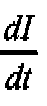

wobei- - U(t) der Wert der Hochspannung zu diesem gegebenen Zeit punkt,- Uc der gewählte Sollwert der Hochspannung und-
- Verfahren nach Anspruch 1, dadurch gekennzeichnet, dass ein anderer Stromparameter ein Stromwert ist, wobei das Verfahren darin besteht, während einer Phase des Anstiegs der Spannung des Generators, soweit der von dem Generator erstellte Wert der Hochspannung kleiner als ein gewählter Sollwert (Uc) der Hochspannung ist, die der Änderung des Stromwerts entsprechende Schwelle (I max (t)) gemäß einem Gesetz der linearen Änderung variieren zu lassen, im Wesentlichen der Art:

wobei- Imax (t) der Wert der Schwelle entsprechend dem Stromwert zu einem gegebenen Zeitpunkt,- U (t) der Wert der Hochspannung zu diesem gegebenen Zeitpunkt,- Uc der gewählte Sollwert der Hochspannung und- Imax der maximale Stromwert entsprechend diesem Sollwert sind. - Verfahren nach einem der vorhergehenden Ansprüche, dadurch gekennzeichnet, dass es außerdem darin besteht, die Sicherheitsauslösemittel zu hemmen (48, 49), wenn die Hochspannung kleiner als ein vorgegebener Wert ist.
- Hochspannungsgenerator, umfassend Mittel zum Erzeugen einer Hochspannung und Sicherheitsauslösemittel, um die Hochspannung abzuschalten, wenn die Gefahr einer Entladung in Form eines Lichtbogens auftritt, umfassend Mittel zum Erzeugen einer variablen, von dem Hochspannungswert abhängigen Auslöseinformation (45, 46), die einem gegebenen Stromparameter zugeordnet ist, und Vergleichsmittel (38, 39) zum Vergleich der Auslöseinformation mit einer Information, die für den Stromparameter selbst repräsentativ ist, wobei die Vergleichsmittel als Antwort eine Steuerinformation für die Sicherheitsauslösemittel erzeugen, dadurch gekennzeichnet, dass der Stromparameter ein Wert der Änderung des Stroms


- Hochspannungsgenerator nach Anspruch 4, dadurch gekennzeichnet, dass ein anderer Stromparameter ein Stromwert I ist und dass er Mittel zum Erzeugen einer Auslöseinformation (45) entsprechend einem Stromwert umfasst, die während einer Phase des Spannungsanstiegs des Generators eingesetzt werden, wobei die Auslöseinformation entsprechend dem Stromwert aus Informationen erzeugt wird, die für die vom Generator gelieferte Hochspannung U(t), den gewählten Sollwert Uc und einen Sollwert der Änderung des maximalen Stroms / max (t) entsprechend dem gewählten Sollwert gemäß einem Gesetz der linearen Änderung repräsentativ sind, Im Wesentlichen der Art:

- Hochspannungsgenerator nach einem beliebigen der Ansprüche 4 oder S, dadurch gekennzeichnet, dass er Vergleichsmittel (48) zum Vergleich einer für die Hochspannung repräsentativen Information mit einer für die minimale Spannung repräsentativen Information umfasst, wobei die Vergleichsmittel mit einem Mittel (49) zu Hemmen der Sicherheitsauslösemittel verbunden sind.
Priority Applications (1)
| Application Number | Priority Date | Filing Date | Title |
|---|---|---|---|
| DE69936614T DE69936614T3 (de) | 1998-06-18 | 1999-06-14 | Verfahren zur Ansteuerung einer Sicherheitsauslösungsvorrichtung in einem Hochspannungsgenerator und Hochspannungsgenerator zur Durchführung des Verfahrens |
Applications Claiming Priority (2)
| Application Number | Priority Date | Filing Date | Title |
|---|---|---|---|
| FR9807693A FR2780211B1 (fr) | 1998-06-18 | 1998-06-18 | Procede de commande de moyens de declenchement de securite dans un generateur de haute tension et generateur de haute tension mettant en oeuvre un tel procede |
| FR9807693 | 1998-06-18 |
Publications (3)
| Publication Number | Publication Date |
|---|---|
| EP0966084A1 EP0966084A1 (de) | 1999-12-22 |
| EP0966084B1 EP0966084B1 (de) | 2007-07-25 |
| EP0966084B2 true EP0966084B2 (de) | 2012-10-17 |
Family
ID=9527545
Family Applications (1)
| Application Number | Title | Priority Date | Filing Date |
|---|---|---|---|
| EP99401455A Expired - Lifetime EP0966084B2 (de) | 1998-06-18 | 1999-06-14 | Verfahren zur Ansteuerung einer Sicherheitsauslösungsvorrichtung in einem Hochspannungsgenerator und Hochspannungsgenerator zur Durchführung des Verfahrens |
Country Status (6)
| Country | Link |
|---|---|
| US (1) | US6381109B1 (de) |
| EP (1) | EP0966084B2 (de) |
| JP (1) | JP4406114B2 (de) |
| CA (1) | CA2275222A1 (de) |
| DE (1) | DE69936614T3 (de) |
| FR (1) | FR2780211B1 (de) |
Families Citing this family (14)
| Publication number | Priority date | Publication date | Assignee | Title |
|---|---|---|---|---|
| JP4508497B2 (ja) * | 2001-09-21 | 2010-07-21 | 旭サナック株式会社 | 静電塗装装置 |
| FR2870082B1 (fr) * | 2004-05-07 | 2006-07-07 | Valitec Soc Par Actions Simpli | Eliminateur d'electricite statique, notamment pour le traitement de polymeres |
| FR2873514B1 (fr) * | 2004-07-20 | 2006-11-17 | Virax Sa | Actionneur portatif lineaire et procede de limitation de l'effort maximal d'un moteur d'un tel actionneur |
| DE102008008201B4 (de) * | 2008-01-31 | 2011-07-21 | Haug GmbH & Co. KG., 70771 | Hochspannungsgenerator für Luftionisationsgeräte |
| JP5508622B2 (ja) | 2009-10-02 | 2014-06-04 | トヨタ自動車株式会社 | 高電圧発生装置の断線検出方法 |
| DE102009051877A1 (de) | 2009-11-04 | 2011-05-05 | Dürr Systems GmbH | Beschichtungsverfahren und Beschichtungsanlage mit dynamischer Anpassung der Zerstäuberdrehzahl und der Hochspannung |
| BR112014001356B1 (pt) | 2011-07-21 | 2020-10-20 | Siemens Aktiengesellschaft | método e dispositivo para determinar uma seção com falha de uma linha de fornecimento de energia |
| DE102013022282B3 (de) * | 2013-12-03 | 2015-03-05 | Eisenmann Ag | Mit Innenaufladung arbeitender Hochrotationszerstäuber |
| US9659721B1 (en) | 2014-05-06 | 2017-05-23 | Google Inc. | Circuit breakers with integrated safety, control, monitoring, and protection features |
| US9966206B1 (en) * | 2015-05-06 | 2018-05-08 | Google Llc | Circuit breakers with integrated safety, control, monitoring, and protection features |
| JP6532613B2 (ja) * | 2017-04-19 | 2019-06-19 | 花王株式会社 | 被膜の製造方法及び静電スプレー装置 |
| FR3089707B1 (fr) * | 2018-12-11 | 2021-10-08 | Safran Electrical & Power | Système électronique de coupure de courant doté d’une solution de coupure rapide. |
| KR102602048B1 (ko) * | 2018-12-21 | 2023-11-15 | 요트. 바그너 게엠베하 | 전기수력학적 분무기의 기능 제어 |
| JP7108803B1 (ja) | 2022-02-14 | 2022-07-28 | シーエフティー エルエルシー | 塗装装置及び高電圧安全制御方法 |
Citations (2)
| Publication number | Priority date | Publication date | Assignee | Title |
|---|---|---|---|---|
| EP0185311B1 (de) † | 1984-12-17 | 1989-04-19 | Behr-Industrieanlagen GmbH & Co. | Verfahren und Vorrichtung zur Betriebsüberwachung einer elektrostatischen Beschichtungsanlage |
| US5138513A (en) † | 1991-01-23 | 1992-08-11 | Ransburg Corporation | Arc preventing electrostatic power supply |
Family Cites Families (10)
| Publication number | Priority date | Publication date | Assignee | Title |
|---|---|---|---|---|
| US4276591A (en) * | 1979-05-29 | 1981-06-30 | The Perkin-Elmer Corporation | Programmable power regulating power supply |
| US4266262A (en) * | 1979-06-29 | 1981-05-05 | Binks Manufacturing Company | Voltage controlled power supply for electrostatic coating apparatus |
| FR2551928B1 (fr) * | 1983-09-14 | 1986-05-23 | Sames Sa | Dispositif de protection des circuits basse tension d'equipement de projection electrostatique, et equipement de projection incorporant ce dispositif |
| DE3444554A1 (de) * | 1984-12-06 | 1986-06-12 | Ernst Roederstein Spezialfabrik für Kondensatoren GmbH, 8300 Landshut | Schaltungsanordnung zur spannungs- und stromstabilisierung eines hochspannungsgenerators |
| FR2608853B1 (fr) | 1986-12-19 | 1992-10-16 | Sames Sa | Procede de controle et de protection contre les arcs electriques dans un dispositif generateur de haute-tension et dispositif mettant en oeuvre ce procede |
| JPH073796Y2 (ja) * | 1988-04-19 | 1995-01-30 | 神鋼電機株式会社 | 異常短絡保護回路 |
| US5224006A (en) * | 1991-09-26 | 1993-06-29 | Westinghouse Electric Corp. | Electronic circuit breaker with protection against sputtering arc faults and ground faults |
| EP0626208B2 (de) * | 1993-04-08 | 2004-09-29 | Nordson Corporation | Stromversorgung für eine elektrostatische Sprühpistole |
| JPH08251907A (ja) * | 1995-03-08 | 1996-09-27 | Toshiba Corp | 半導体遮断器 |
| FR2743207B1 (fr) * | 1995-12-29 | 1998-03-27 | Valeo Electronique | Procede et dispositif pour la protection d'un element a impedance reglable commandant l'alimentation d'un moteur electrique, notamment de vehicule automobile |
-
1998
- 1998-06-18 FR FR9807693A patent/FR2780211B1/fr not_active Expired - Lifetime
-
1999
- 1999-06-11 US US09/330,862 patent/US6381109B1/en not_active Expired - Lifetime
- 1999-06-14 EP EP99401455A patent/EP0966084B2/de not_active Expired - Lifetime
- 1999-06-14 DE DE69936614T patent/DE69936614T3/de not_active Expired - Lifetime
- 1999-06-16 CA CA002275222A patent/CA2275222A1/fr not_active Abandoned
- 1999-06-18 JP JP17243599A patent/JP4406114B2/ja not_active Expired - Lifetime
Patent Citations (2)
| Publication number | Priority date | Publication date | Assignee | Title |
|---|---|---|---|---|
| EP0185311B1 (de) † | 1984-12-17 | 1989-04-19 | Behr-Industrieanlagen GmbH & Co. | Verfahren und Vorrichtung zur Betriebsüberwachung einer elektrostatischen Beschichtungsanlage |
| US5138513A (en) † | 1991-01-23 | 1992-08-11 | Ransburg Corporation | Arc preventing electrostatic power supply |
Also Published As
| Publication number | Publication date |
|---|---|
| JP2000115988A (ja) | 2000-04-21 |
| DE69936614D1 (de) | 2007-09-06 |
| EP0966084A1 (de) | 1999-12-22 |
| DE69936614T2 (de) | 2008-05-21 |
| FR2780211A1 (fr) | 1999-12-24 |
| FR2780211B1 (fr) | 2000-09-08 |
| EP0966084B1 (de) | 2007-07-25 |
| CA2275222A1 (fr) | 1999-12-18 |
| US6381109B1 (en) | 2002-04-30 |
| JP4406114B2 (ja) | 2010-01-27 |
| DE69936614T3 (de) | 2013-03-28 |
Similar Documents
| Publication | Publication Date | Title |
|---|---|---|
| EP0966084B1 (de) | Verfahren zur Ansteuerung einer Sicherheitsauslösungsvorrichtung in einem Hochspannungsgenerator und Hochspannungsgenerator zur Durchführung des Verfahrens | |
| EP0190961B1 (de) | Gleichstromversorgung mit verstellbarem Arbeitspunkt | |
| FR2522210A1 (fr) | Circuit de commande d'une source d'alimentation en courant continu a haute tension pour un appareil electrostatique | |
| EP1009006B1 (de) | Standardeinrichtung zur Steuerung eines Elektromagneten zum Öffnen oder Schliessen eines Schutzschalters | |
| EP0219409B1 (de) | Elektrostatisches Spritzgerät mit Vorrichtung zum Verhindern von Lichtbogen | |
| EP0330561A1 (de) | Mehrfunktionsregeleinrichtung mit Taktsynchronwechselstromerzeuger | |
| EP0463892A1 (de) | Niederspannungs-/Hochspannungskonverter | |
| EP0493238B1 (de) | Schutzschaltung gegen Kurzschlüsse für elektronische Schalter | |
| EP3399612B1 (de) | Elektrischer anschluss, der eine elektrische schutzvorrichtung zur stromvorspannung umfasst | |
| EP3473836A1 (de) | Zündsystem eines turbotriebwerks eines luftfahrzeugs | |
| EP0753923B1 (de) | Verfahren, Einrichtung zum Herstellung höher Spannung und Anlage zum Spritzen von Beschichtungsmaterialien | |
| EP3483999A1 (de) | Elektrische verbindung für die übertragung einer hochspannung über wechselstrom an ein benutzergerät | |
| EP0753350B1 (de) | Verfahren zum Herstellung höher Spannung und Anlage zum Spritzen von Beschichtungsmaterialien | |
| EP1009004A1 (de) | Einrichtung zur Steuerung eines Elektromagneten, mit Erfassung von unbeabsichtigten Bewegen des beweglichen Kerns eines Elektromagneten | |
| EP0921305B1 (de) | Verfahren und Vorrichtung zur Steuerung des Stromzufuhrs einer Schalterwicklung für Kraftfahrzeuganlasser | |
| EP1870976A2 (de) | Vorrichtung zum Schutz gegen Überspannungen mit verbesserter Fähigkeit zur Notabsperrung durch Abschalten und entsprechendes Verfahren | |
| FR2721474A1 (fr) | Dispositif de commande d'une lampe fluorescente à basse pression. | |
| EP3824522B1 (de) | Vorrichtung zur emulation eines bimetallstreifens und vorrichtung zum schutz einer elektrischen leitung gegen überspannungen | |
| FR2870986A1 (fr) | Dispositif de commande de relais pour appareil electrique en courant continu | |
| EP3650875B1 (de) | Verfahren zum testen von einer elektrischen schutzeinrichtung und elektrische schutzeinrichtung, die ein solches verfahren durchführt | |
| EP0827250B1 (de) | Elektronischer Auslöser mit einem thermischen Speicher | |
| FR2819353A1 (fr) | Regulateur et procede de production d'energie pour un vehicule | |
| EP3883077B1 (de) | Geräte zum elektrischen schutz und entsprechende verfahren | |
| EP0851563B1 (de) | Schaltnetzteileinrichtung mit kontrollierter elektromagnetischer Störung | |
| EP0768683A1 (de) | Stromversorgungsschaltung für eine Erregerspule eines Elktromagneten |
Legal Events
| Date | Code | Title | Description |
|---|---|---|---|
| PUAI | Public reference made under article 153(3) epc to a published international application that has entered the european phase |
Free format text: ORIGINAL CODE: 0009012 |
|
| AK | Designated contracting states |
Kind code of ref document: A1 Designated state(s): BE CH DE ES GB GR IT LI NL PT SE |
|
| AX | Request for extension of the european patent |
Free format text: AL;LT;LV;MK;RO;SI |
|
| 17P | Request for examination filed |
Effective date: 20000128 |
|
| AKX | Designation fees paid |
Free format text: BE CH DE ES GB GR IT LI NL PT SE |
|
| RAP1 | Party data changed (applicant data changed or rights of an application transferred) |
Owner name: SAMES TECHNOLOGIES |
|
| GRAP | Despatch of communication of intention to grant a patent |
Free format text: ORIGINAL CODE: EPIDOSNIGR1 |
|
| GRAS | Grant fee paid |
Free format text: ORIGINAL CODE: EPIDOSNIGR3 |
|
| GRAA | (expected) grant |
Free format text: ORIGINAL CODE: 0009210 |
|
| AK | Designated contracting states |
Kind code of ref document: B1 Designated state(s): BE CH DE ES GB GR IT LI NL PT SE |
|
| REG | Reference to a national code |
Ref country code: GB Ref legal event code: FG4D Free format text: NOT ENGLISH |
|
| REG | Reference to a national code |
Ref country code: CH Ref legal event code: EP |
|
| REF | Corresponds to: |
Ref document number: 69936614 Country of ref document: DE Date of ref document: 20070906 Kind code of ref document: P |
|
| PG25 | Lapsed in a contracting state [announced via postgrant information from national office to epo] |
Ref country code: PT Free format text: LAPSE BECAUSE OF FAILURE TO SUBMIT A TRANSLATION OF THE DESCRIPTION OR TO PAY THE FEE WITHIN THE PRESCRIBED TIME-LIMIT Effective date: 20071226 Ref country code: NL Free format text: LAPSE BECAUSE OF FAILURE TO SUBMIT A TRANSLATION OF THE DESCRIPTION OR TO PAY THE FEE WITHIN THE PRESCRIBED TIME-LIMIT Effective date: 20070725 Ref country code: ES Free format text: LAPSE BECAUSE OF FAILURE TO SUBMIT A TRANSLATION OF THE DESCRIPTION OR TO PAY THE FEE WITHIN THE PRESCRIBED TIME-LIMIT Effective date: 20071105 |
|
| NLV1 | Nl: lapsed or annulled due to failure to fulfill the requirements of art. 29p and 29m of the patents act | ||
| GBV | Gb: ep patent (uk) treated as always having been void in accordance with gb section 77(7)/1977 [no translation filed] |
Effective date: 20070725 |
|
| PG25 | Lapsed in a contracting state [announced via postgrant information from national office to epo] |
Ref country code: GR Free format text: LAPSE BECAUSE OF FAILURE TO SUBMIT A TRANSLATION OF THE DESCRIPTION OR TO PAY THE FEE WITHIN THE PRESCRIBED TIME-LIMIT Effective date: 20071026 |
|
| PLBI | Opposition filed |
Free format text: ORIGINAL CODE: 0009260 |
|
| PLAX | Notice of opposition and request to file observation + time limit sent |
Free format text: ORIGINAL CODE: EPIDOSNOBS2 |
|
| PG25 | Lapsed in a contracting state [announced via postgrant information from national office to epo] |
Ref country code: GB Free format text: LAPSE BECAUSE OF FAILURE TO SUBMIT A TRANSLATION OF THE DESCRIPTION OR TO PAY THE FEE WITHIN THE PRESCRIBED TIME-LIMIT Effective date: 20070725 |
|
| 26 | Opposition filed |
Opponent name: DUERR SYSTEMS GMBH Effective date: 20080423 |
|
| PG25 | Lapsed in a contracting state [announced via postgrant information from national office to epo] |
Ref country code: SE Free format text: LAPSE BECAUSE OF FAILURE TO SUBMIT A TRANSLATION OF THE DESCRIPTION OR TO PAY THE FEE WITHIN THE PRESCRIBED TIME-LIMIT Effective date: 20071025 |
|
| PLAF | Information modified related to communication of a notice of opposition and request to file observations + time limit |
Free format text: ORIGINAL CODE: EPIDOSCOBS2 |
|
| PLBB | Reply of patent proprietor to notice(s) of opposition received |
Free format text: ORIGINAL CODE: EPIDOSNOBS3 |
|
| BERE | Be: lapsed |
Owner name: SAMES TECHNOLOGIES Effective date: 20080630 |
|
| REG | Reference to a national code |
Ref country code: CH Ref legal event code: PL |
|
| PG25 | Lapsed in a contracting state [announced via postgrant information from national office to epo] |
Ref country code: BE Free format text: LAPSE BECAUSE OF NON-PAYMENT OF DUE FEES Effective date: 20080630 |
|
| PG25 | Lapsed in a contracting state [announced via postgrant information from national office to epo] |
Ref country code: LI Free format text: LAPSE BECAUSE OF NON-PAYMENT OF DUE FEES Effective date: 20080630 Ref country code: CH Free format text: LAPSE BECAUSE OF NON-PAYMENT OF DUE FEES Effective date: 20080630 |
|
| PG25 | Lapsed in a contracting state [announced via postgrant information from national office to epo] |
Ref country code: IT Free format text: LAPSE BECAUSE OF NON-PAYMENT OF DUE FEES Effective date: 20080630 |
|
| PUAH | Patent maintained in amended form |
Free format text: ORIGINAL CODE: 0009272 |
|
| STAA | Information on the status of an ep patent application or granted ep patent |
Free format text: STATUS: PATENT MAINTAINED AS AMENDED |
|
| 27A | Patent maintained in amended form |
Effective date: 20121017 |
|
| AK | Designated contracting states |
Kind code of ref document: B2 Designated state(s): BE CH DE ES GB GR IT LI NL PT SE |
|
| REG | Reference to a national code |
Ref country code: DE Ref legal event code: R102 Ref document number: 69936614 Country of ref document: DE Effective date: 20121017 |
|
| REG | Reference to a national code |
Ref country code: DE Ref legal event code: R082 Ref document number: 69936614 Country of ref document: DE Representative=s name: PFENNING, MEINIG & PARTNER MBB PATENTANWAELTE, DE Ref country code: DE Ref legal event code: R081 Ref document number: 69936614 Country of ref document: DE Owner name: SAMES KREMLIN, FR Free format text: FORMER OWNER: SAMES TECHNOLOGIES, MEYLAN, FR |
|
| PGFP | Annual fee paid to national office [announced via postgrant information from national office to epo] |
Ref country code: DE Payment date: 20180522 Year of fee payment: 20 |
|
| REG | Reference to a national code |
Ref country code: DE Ref legal event code: R071 Ref document number: 69936614 Country of ref document: DE |