EP0965500A2 - Dispositif de sac à air pour véhicule et son procédé de commande - Google Patents
Dispositif de sac à air pour véhicule et son procédé de commande Download PDFInfo
- Publication number
- EP0965500A2 EP0965500A2 EP99109297A EP99109297A EP0965500A2 EP 0965500 A2 EP0965500 A2 EP 0965500A2 EP 99109297 A EP99109297 A EP 99109297A EP 99109297 A EP99109297 A EP 99109297A EP 0965500 A2 EP0965500 A2 EP 0965500A2
- Authority
- EP
- European Patent Office
- Prior art keywords
- sensor
- gas cushion
- gas
- signal
- filling device
- Prior art date
- Legal status (The legal status is an assumption and is not a legal conclusion. Google has not performed a legal analysis and makes no representation as to the accuracy of the status listed.)
- Withdrawn
Links
Images


Classifications
-
- B—PERFORMING OPERATIONS; TRANSPORTING
- B60—VEHICLES IN GENERAL
- B60R—VEHICLES, VEHICLE FITTINGS, OR VEHICLE PARTS, NOT OTHERWISE PROVIDED FOR
- B60R21/00—Arrangements or fittings on vehicles for protecting or preventing injuries to occupants or pedestrians in case of accidents or other traffic risks
- B60R21/01—Electrical circuits for triggering passive safety arrangements, e.g. airbags, safety belt tighteners, in case of vehicle accidents or impending vehicle accidents
- B60R21/015—Electrical circuits for triggering passive safety arrangements, e.g. airbags, safety belt tighteners, in case of vehicle accidents or impending vehicle accidents including means for detecting the presence or position of passengers, passenger seats or child seats, and the related safety parameters therefor, e.g. speed or timing of airbag inflation in relation to occupant position or seat belt use
- B60R21/01512—Passenger detection systems
- B60R21/01528—Passenger detection systems mounted on the bag
-
- B—PERFORMING OPERATIONS; TRANSPORTING
- B60—VEHICLES IN GENERAL
- B60R—VEHICLES, VEHICLE FITTINGS, OR VEHICLE PARTS, NOT OTHERWISE PROVIDED FOR
- B60R21/00—Arrangements or fittings on vehicles for protecting or preventing injuries to occupants or pedestrians in case of accidents or other traffic risks
- B60R21/01—Electrical circuits for triggering passive safety arrangements, e.g. airbags, safety belt tighteners, in case of vehicle accidents or impending vehicle accidents
- B60R21/015—Electrical circuits for triggering passive safety arrangements, e.g. airbags, safety belt tighteners, in case of vehicle accidents or impending vehicle accidents including means for detecting the presence or position of passengers, passenger seats or child seats, and the related safety parameters therefor, e.g. speed or timing of airbag inflation in relation to occupant position or seat belt use
- B60R21/01508—Electrical circuits for triggering passive safety arrangements, e.g. airbags, safety belt tighteners, in case of vehicle accidents or impending vehicle accidents including means for detecting the presence or position of passengers, passenger seats or child seats, and the related safety parameters therefor, e.g. speed or timing of airbag inflation in relation to occupant position or seat belt use detecting forces or pressure in bags or modules
-
- B—PERFORMING OPERATIONS; TRANSPORTING
- B60—VEHICLES IN GENERAL
- B60R—VEHICLES, VEHICLE FITTINGS, OR VEHICLE PARTS, NOT OTHERWISE PROVIDED FOR
- B60R21/00—Arrangements or fittings on vehicles for protecting or preventing injuries to occupants or pedestrians in case of accidents or other traffic risks
- B60R21/01—Electrical circuits for triggering passive safety arrangements, e.g. airbags, safety belt tighteners, in case of vehicle accidents or impending vehicle accidents
- B60R21/015—Electrical circuits for triggering passive safety arrangements, e.g. airbags, safety belt tighteners, in case of vehicle accidents or impending vehicle accidents including means for detecting the presence or position of passengers, passenger seats or child seats, and the related safety parameters therefor, e.g. speed or timing of airbag inflation in relation to occupant position or seat belt use
- B60R21/01512—Passenger detection systems
- B60R21/01516—Passenger detection systems using force or pressure sensing means
- B60R21/01526—Passenger detection systems using force or pressure sensing means using piezoelectric elements
Definitions
- the invention relates to an airbag device for a motor vehicle, with one in a row a sensor activation by a filling device with gas inflatable gas cushion, which can be pushed forward when inflated into a passenger compartment of the motor vehicle, and with a control device controlling the filling device by a control signal, wherein the amount of gas delivered to the gas cushion by the filler in response to a Sensor signal from a sensor that detects the advancing movement of the gas cushion Scanning medium is supplied, is controllable, and a method for controlling the same.
- Such an airbag device for a motor vehicle is known from EP 0 812 741. It is provided that the scanning device with the front part of the gas cushion connected scanning medium, which is designed in such a way that it carries out the feed movement of the gas cushion and this feed movement can be scanned.
- the scanning medium is in the form of a thread or one Band formed on the inside of the front part of the gas cushion is attached.
- the thread or the tape follows it Feed the unfolding gas cushion, so that by scanning the Extension length and / or the extension time of the tape or thread Feed movement of the gas cushion is detectable.
- the gas cushion is so long filled until an object during the advance moves the gas cushion at Unfolding hampers. For example, this may be too close to the gas cushion Body part of the vehicle occupant, for example its head or upper body, the are in such a forward position (out-of-position position).
- the known airbag device allows the feed movement of the to disengage the gas cushion when the front of the gas cushion is open an obstacle hits.
- the detection provided in the known airbag device the feed movement by means of the thread or the belt and the complete Turn off the gas supply when the gas cushion front part hits an obstacle however for the constellations that actually occur in accidents in a disadvantageous manner and Way not sufficient to the one hand the vehicle occupants in an accident adequate protection and, on the other hand, an additional risk of injury to the Exclude vehicle occupants by the deploying airbag.
- DE-OS 196 10 833 describes a method and a device for controlling a actuatable restraint, such as of an airbag, known to be discrete Tax zones.
- the device has sensors that have at least two Sensing parameters that an occupant restraint function of the restraint system can affect. These sensors are connected to a controller that selects one of the plurality of discrete control zones of the restraint. It is provided that the control signal of the Controller taking into account the parameters seat back angle, seat position, Belt extension, belt status, occupant position, occupant weight, temperature and the Signals from a collision sensor, a height sensor and the Vehicle speed is generated.
- the device according to the invention in that the at least one on a local side of the gas cushion moving toward the occupant Sensor element that acts as a sensing medium and responds to pressure changes is arranged, by which characterizes the sensed pressure change Sensor signal can be generated, which to control the filling device Control device is conductive.
- the inventive method provides that a change in pressure on the Occupant-moving side of the unfolding gas cushion by at least one this arranged, pressure-sensitive sensor element detects this Pressure change characterizing sensor signal is generated, which to which the Filling device for the gas cushion controlling control device is directed.
- the measures according to the invention have the advantage that they make it possible to Unfolding and the retention of the gas cushion of the airbag device so too control that in an out-of-position situation or in a critical out-of-position situation no additional risk of injury to the vehicle occupant the unfolding airbag arise.
- the Restraint effect of the airbag through a continuous, quasi-continuous or too Evaluation of the sensor signal or signals taking place at discrete times Pressure sensitive sensors arranged at the front of the gas cushion are controlled become.
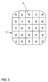
- An advantageous development of the invention provides that a plurality of over defined area on the side of the vehicle moving towards the occupant Gas cushion distributed arranged pressure-sensitive sensor elements is provided.
- Such a measure has the advantage that not only a local one Pressure change, but a pressure distribution is sensible, which is advantageous and This allows conclusions to be drawn about the size, location and possibly the shape of the Spread the gas cushion to pull the disabled object, so that in an advantageous manner and how an improved position detection is achieved.
- control device not only the signal initiating the deployment of the airbag gas cushion Accident sensor and the sensor signal on the moving toward the occupant Side of the gas cushion located at least one sensor element are supplied, but that further static and / or dynamic characterizing the course of the accident Parameters are included in the control process. These measures will result in an advantageous way of tracking the filling level of the gas cushion enables.
- Another advantageous development of the invention provides that an acceleration / deceleration sensor is arranged in the vehicle, the measurement signal of one Control device is supplied.
- This measure has the advantage that from the Sensor element of the airbag device according to the invention delivered sensor signal and the portion of the measurement signals supplied by the acceleration / deceleration sensor the occupant mass can be determined dynamically, which is from the gas cushion of the airbag device must be withheld in the event of a collision. This will be more advantageous Way an adjustment of the filling pressure of the gas cushion of the invention Airbag device allows for the accident.
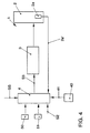
- FIGS. 1-3 show an embodiment of an airbag device, generally designated 1 shown for a motor vehicle, which is in principle in a gas cushion 2, a preferably single or multi-stage filling device 3 for generating a Gas cushion 2 filling gas and a filling device 3 via a control signal ST Controlling control device 4, the sensor signals S1 of an accident sensor 5 supplied be structured.
- an airbag device 1 is known and therefore does not have to are explained in more detail.
- the use of a single sensor element 10 is sufficient to determine that an object hampers the deployment of the gas cushion 2. But it will preferred that in a defined area the moving towards the occupant Side 2 'of the gas cushion 2, a plurality of sensor elements 10 are arranged, the Sensor signals S2 of the control device 4 are supplied. This will in advantageously achieved an increased resolution, which then allows, not only the presence of an object, but also its shape and / or size sense. It can also be provided that instead of discrete sensor elements 10 on the side of the gas cushion 2 moving toward the occupant, a printing film or a tactile sensor are arranged, the sensor signals S2 of which are sent to the control device 4 are conductive. It is also possible that at least in a portion of the Occupant side 2 'of the gas cushion pressure sensors are printed.
- the gas cushion 2 has a preferably multi-layer structure in order to Sensor element 10 thermally from the gas located in the interior of the gas cushion 2 isolate.
- the sensor element 10 consists of the actual sensor 11, which e.g. is a pressure sensitive switch or a piezo element.
- the sensor 11 generated signals are then via corresponding lines 12a, 12b to Control device 4 passed.
- the position of the Spread of the gas cushion 2 disabled object determined. Since the Spreading speed and the spreading behavior of the occupant Moving side 2 'of the gas cushion 2 are known and reproducible, can of the Control device 4 between the ignition timing of the filling device 3 and that of the Sensor elements 10 sensed the time of contact between the occupants moving side 2 'of the gas cushion 2 and the object a distance relationship are produced so that the control device 4 can determine whether the object is in the COOP area, in the OOP area or in the IP (in-position) area.
- the Control device 4 determines whether there is an object in the COOP area if between the Ignition time of the filling device 3 and the contact time a period of about 0-5 ms lies. A position of the object in the OOP area is then determined by the Control device 4 assumed if the aforementioned period in the range typically lies between approx. 6 and approx. 12 ms. With a more than approx. 12 ms permanent period of time, the control device 4 generally assumes that the Object is in the IP range.
- the control device 4 If the control device 4 now determines that this is the spread of the gas cushion 2 obstructing object in the COOP, OOP or IP range, the Filling device 3 controlled so that an injury to the vehicle occupant by the unfolding gas cushion 2 is eliminated or at least reduced by the inflow of the gas generated by the filling device 3 to the gas cushion 2 is drastically reduced and / or is interrupted (COOP situation), reduced (OOP situation) or is maintained unabated (IP situation).
- COOP situation interrupted
- OOP situation reduced
- IP situation unabated
- the temporal development of the contact between the Occupant-moving side 2 'of the gas cushion 2 and the object is registered.
- the sensor elements 10 on the front 2 'of the gas cushion 2 continuously, quasi-continuously or deliver the sensor signal S2 at discrete times is the temporal Development of the contact between the gas cushion 2 and the object easy to grasp: E.g. determined by the control device 4 that the first contact between Gas cushion and object within a period of approx. 0-5 ms after ignition of the Filling device takes place, that is, that the spreading of the gas cushion 2 hinders Object is in the COOP area, and this contact lasts longer than e.g. 3 ms and / or if the sensed imprint of the object increases during this time, the Assumption that the vehicle occupant is in the COOP area is confirmed, so that then the filling device 3 is reduced accordingly.
- the evaluation of the time course of the sensed contact reveals that the Contact state less than e.g. 3 ms lasts and / or the impression changes during this time reduced, it can be assumed that the performance of the filling device 3 can be maintained or enlarged without endangering the vehicle occupants.
- Corresponding control algorithms are also possible for the OOP area.
- the retaining function of the gas cushion 2 of the airbag device 1 is designed such that the available Delay route of the occupant, i.e. the survival space, is optimally used.
- the internal pressure of the gas cushion 2 as a function of one or more of the influencing factors mentioned in the previous paragraph is controlled that with less occupant mass and / or less accident severity and / or with the belt GS applied, the internal pressure of the gas cushion 2 of the airbag device 1 is not as high as with a large occupant mass and / or high Severity of the accident and / or with the belt not fastened.
- the occupant mass is an essential parameter.
- the described Airbag device 1 now allows to determine the occupant mass up to now arranged under the seat of the seat to dispense measuring elements 51 and the Proportional occupant mass to be retained in the airbag directly via the sensor signal S2 of the To calculate sensor element 10.
- a Acceleration / deceleration sensor 40 (see Figure 4) is arranged, which the Measures acceleration / deceleration of the motor vehicle at least at the time of the accident.
- the output signal S2 of the sensor element 10 from the occupant to the Gas cushion 2 exerted force is known from the sensor element 10 measured force impact of the occupant on the gas cushion 2 and the Acceleration / deceleration sensor 40 measured acceleration / deceleration the restrained occupant mass is calculated, which is equal to the quotient of force acting on the gas cushion 2 and the acceleration / deceleration of the Inmates is.
- the gas cushion 2 is not the static one of those in the seat arranged measuring elements 51 measured occupant mass, but dynamically the mass to be collected from the gas cushion 2.
- a measuring filler 2a arranged in the gas cushion 2 measures the actual internal pressure in the gas cushion 2. Its output signal 2a 'becomes Control device 4 fed back, the predetermined target value with the measured Comparing the actual value and then generating a control signal S3 for the filling device 3, so that the amount of gas generated by the filling device 3 is increased accordingly or is reduced.
- the airbag device 1 described characterized in that the unfolding and retention effect of the gas cushion 2 such can control that in a COOP or in an OOP situation no additional Risk of injury due to the unfolding of the gas cushion 2 and the Restraint function of the airbag device 1 during the entire accident Controllable depending on the accident severity, occupant mass and other parameters is.
Applications Claiming Priority (2)
| Application Number | Priority Date | Filing Date | Title |
|---|---|---|---|
| DE19827135 | 1998-06-18 | ||
| DE1998127135 DE19827135A1 (de) | 1998-06-18 | 1998-06-18 | Airbag-Vorrichtung für ein Kraftfahrzeug sowie Verfahren zur Steuerung derselben |
Publications (2)
| Publication Number | Publication Date |
|---|---|
| EP0965500A2 true EP0965500A2 (fr) | 1999-12-22 |
| EP0965500A3 EP0965500A3 (fr) | 2000-10-18 |
Family
ID=7871259
Family Applications (1)
| Application Number | Title | Priority Date | Filing Date |
|---|---|---|---|
| EP99109297A Withdrawn EP0965500A3 (fr) | 1998-06-18 | 1999-05-27 | Dispositif de sac à air pour véhicule et son procédé de commande |
Country Status (2)
| Country | Link |
|---|---|
| EP (1) | EP0965500A3 (fr) |
| DE (1) | DE19827135A1 (fr) |
Cited By (4)
| Publication number | Priority date | Publication date | Assignee | Title |
|---|---|---|---|---|
| EP1244579A1 (fr) * | 1999-12-23 | 2002-10-02 | Z/C Holding Company | Ensemble de coussins gonflables pour vehicules |
| EP1558468A1 (fr) * | 2002-11-08 | 2005-08-03 | Key Safety Systems, Inc. | Capteur de position d'occupant pour systeme d'airbag |
| US7523956B2 (en) | 1999-12-23 | 2009-04-28 | Zumpano Bernard J | Inflatable restraint assembly for vehicles |
| CN115607865A (zh) * | 2022-10-21 | 2023-01-17 | 深圳学教王科技有限公司 | 一种分布式快速启动紧急救援气囊及救援方法 |
Families Citing this family (6)
| Publication number | Priority date | Publication date | Assignee | Title |
|---|---|---|---|---|
| JP4163117B2 (ja) | 2001-11-17 | 2008-10-08 | フォルクスワーゲン・アクチェンゲゼルシャフト | 車両用、特に原動機付き車両用のエアバッグ装置 |
| DE10213907C1 (de) * | 2002-03-28 | 2003-07-31 | Autoliv Dev | Gassackeinrichtung mit Radarsteuerung |
| DE102005014603A1 (de) * | 2005-03-31 | 2006-10-05 | Conti Temic Microelectronic Gmbh | Aufblasvorrichtung und -verfahren für einen Airbag |
| DE102005026775A1 (de) * | 2005-06-10 | 2006-12-28 | Bayerische Motoren Werke Ag | Fahrzeug mit einer regelbaren Rückhalteeinrichtung |
| DE102008002243B4 (de) | 2008-06-05 | 2020-06-18 | Robert Bosch Gmbh | Verfahren, Steuergerät und Computerprogrammprodukt zum Bestimmen einer Beschleunigung eines Insassen eines Fahrzeugs |
| DE102014222035A1 (de) * | 2014-10-29 | 2016-05-04 | Bayerische Motoren Werke Aktiengesellschaft | Airbagsystem für ein Kraftfahrzeug |
Citations (2)
| Publication number | Priority date | Publication date | Assignee | Title |
|---|---|---|---|---|
| DE19610833A1 (de) | 1995-03-22 | 1996-09-26 | Trw Vehicle Safety Systems | Verfahren und Vorrichtung zum Steuern einer betätigbaren Rückhalteeinrichtung, und zwar ansprechend auf diskrete Steuerzonen |
| EP0812741A1 (fr) | 1996-03-22 | 1997-12-17 | HS Technik und Design Technische Entwicklungen GmbH | Dispositif de coussin gonflable dans un véhicule automobile |
Family Cites Families (6)
| Publication number | Priority date | Publication date | Assignee | Title |
|---|---|---|---|---|
| DE4041049A1 (de) * | 1990-12-20 | 1992-07-02 | Siemens Ag | Steueranordnung fuer einen airbag eines fahrzeuges |
| DE19526334A1 (de) * | 1995-07-19 | 1997-01-23 | Bosch Gmbh Robert | Sicherheitseinrichtung für Fahrzeuginsassen |
| DE19611384C2 (de) * | 1996-03-22 | 2001-05-31 | Hs Tech & Design | Airbagvorrichtung in einem Kraftfahrzeug |
| DE19625730A1 (de) * | 1996-06-27 | 1998-01-02 | Teves Gmbh Alfred | Verwendung einer Berührungssensormatrix als Sensor in Kraftfahrzeugen |
| JPH1035405A (ja) * | 1996-07-18 | 1998-02-10 | Fuji Heavy Ind Ltd | 車両用エアバッグ装置のガス圧調整装置 |
| EP0836971B1 (fr) * | 1996-08-22 | 2002-07-17 | Volkswagen Aktiengesellschaft | Système de protection des occupants pour un véhicule |
-
1998
- 1998-06-18 DE DE1998127135 patent/DE19827135A1/de not_active Withdrawn
-
1999
- 1999-05-27 EP EP99109297A patent/EP0965500A3/fr not_active Withdrawn
Patent Citations (2)
| Publication number | Priority date | Publication date | Assignee | Title |
|---|---|---|---|---|
| DE19610833A1 (de) | 1995-03-22 | 1996-09-26 | Trw Vehicle Safety Systems | Verfahren und Vorrichtung zum Steuern einer betätigbaren Rückhalteeinrichtung, und zwar ansprechend auf diskrete Steuerzonen |
| EP0812741A1 (fr) | 1996-03-22 | 1997-12-17 | HS Technik und Design Technische Entwicklungen GmbH | Dispositif de coussin gonflable dans un véhicule automobile |
Cited By (7)
| Publication number | Priority date | Publication date | Assignee | Title |
|---|---|---|---|---|
| EP1244579A1 (fr) * | 1999-12-23 | 2002-10-02 | Z/C Holding Company | Ensemble de coussins gonflables pour vehicules |
| EP1244579A4 (fr) * | 1999-12-23 | 2005-10-26 | Z C Holding Company | Ensemble de coussins gonflables pour vehicules |
| US7523956B2 (en) | 1999-12-23 | 2009-04-28 | Zumpano Bernard J | Inflatable restraint assembly for vehicles |
| EP1558468A1 (fr) * | 2002-11-08 | 2005-08-03 | Key Safety Systems, Inc. | Capteur de position d'occupant pour systeme d'airbag |
| EP1558468A4 (fr) * | 2002-11-08 | 2010-08-04 | Key Safety Systems Inc | Capteur de position d'occupant pour systeme d'airbag |
| CN115607865A (zh) * | 2022-10-21 | 2023-01-17 | 深圳学教王科技有限公司 | 一种分布式快速启动紧急救援气囊及救援方法 |
| CN115607865B (zh) * | 2022-10-21 | 2023-08-04 | 深圳学教王科技有限公司 | 一种分布式快速启动紧急救援气囊及救援方法 |
Also Published As
| Publication number | Publication date |
|---|---|
| EP0965500A3 (fr) | 2000-10-18 |
| DE19827135A1 (de) | 1999-12-23 |
Similar Documents
| Publication | Publication Date | Title |
|---|---|---|
| EP0636074B1 (fr) | Procede et dispositif de protection des occupants d'un vehicule automobile | |
| EP1122136B1 (fr) | Procédé et dispositif de sécurité assurant le maintien d'un occupant dans un siège de véhicule | |
| EP1771320B1 (fr) | Vehicule automobile equipe d'un systeme de securite agissant a titre preventif | |
| DE69917562T2 (de) | Verfahren und Vorrichtung zur Bestimmung des Zündzeitpunktes einer Insassen-Rückhaltevorrichung unter Verwendung von Insassensensoreingängen | |
| DE19930384B4 (de) | Schutzeinrichtung für Fahrzeuginsassen | |
| EP1160134B1 (fr) | Système de retenue de passager | |
| DE19956530A1 (de) | Insassen-Rückhaltevorrichtung und Verfahren zum Steuern der Insassen-Rückhaltevorrichtung | |
| DE19842939B4 (de) | Aktivierungssteuerungsvorrichtung für eine passive Sicherheitseinrichtung | |
| DE102005013164B4 (de) | Verfahren und Vorrichtung zur Steuerung eines passiven Rückhaltesystems | |
| DE102006021380A1 (de) | Fahrzeuginsassen-Sicherheitssystem und Verfahren zur Erkennung der Position eines Fahrzeuginsassen | |
| EP0965500A2 (fr) | Dispositif de sac à air pour véhicule et son procédé de commande | |
| EP1012007B1 (fr) | Dispositif pour la protection des occupants dans un vehicule automobile et procede pour commander le gonflage d'un coussin gonflable dans un vehicule automobile | |
| DE102004038167B4 (de) | Kraftfahrzeug mit einem präventiv wirkenden Schutzsystem | |
| EP1501704B1 (fr) | Proc d et disposition pour amorcer des dispositifs de retenue | |
| EP1490248B1 (fr) | Procede et dispositif de commande de systemes de retenue qui peuvent etre commandes notamment de facon reversible | |
| EP0796773A2 (fr) | Dispositif de protection des occupants pour véhicules de transport de personnes | |
| EP1442943B1 (fr) | Système de protection pour piétons et méthode de déclenchement d'un tel système selon l'impact | |
| EP0949127B1 (fr) | Dispositif d' airbag pour véhicule et sa méthode de contrôle permettant un dosage contrôlable de la quantité de gaz delivrée | |
| WO2001044024A1 (fr) | Dispositif de retenue reglable, destine a des automobiles | |
| DE19829756C1 (de) | Auslösegerät für ein Insassenschutzsystem | |
| DE102007015957A1 (de) | Verfahren zur Entlüftung eines Fahrzeuggassacks | |
| DE19823005A1 (de) | Airbag-Vorrichtung für ein Kraftfahrzeug sowie Verfahren zur Steuerung derselben | |
| DE102005018979A1 (de) | Rückhaltesystem für ein Kraftfahrzeug und Verfahren zum Auslösen des Rückhaltesystems | |
| EP2036778B1 (fr) | Procede de commande d'elements de retenue irreversibles dependant de la position assise d'un individu | |
| EP1185440A1 (fr) | Dispositif de protection contre les chocs |
Legal Events
| Date | Code | Title | Description |
|---|---|---|---|
| PUAI | Public reference made under article 153(3) epc to a published international application that has entered the european phase |
Free format text: ORIGINAL CODE: 0009012 |
|
| AK | Designated contracting states |
Kind code of ref document: A2 Designated state(s): DE ES FR GB IT PT SE |
|
| AX | Request for extension of the european patent |
Free format text: AL;LT;LV;MK;RO;SI |
|
| PUAL | Search report despatched |
Free format text: ORIGINAL CODE: 0009013 |
|
| AK | Designated contracting states |
Kind code of ref document: A3 Designated state(s): AT BE CH CY DE DK ES FI FR GB GR IE IT LI LU MC NL PT SE |
|
| AX | Request for extension of the european patent |
Free format text: AL;LT;LV;MK;RO;SI |
|
| RIC1 | Information provided on ipc code assigned before grant |
Free format text: 7B 60R 21/32 A, 7B 60R 21/01 B |
|
| 17P | Request for examination filed |
Effective date: 20010418 |
|
| AKX | Designation fees paid |
Free format text: DE ES FR GB IT PT SE |
|
| 17Q | First examination report despatched |
Effective date: 20030318 |
|
| STAA | Information on the status of an ep patent application or granted ep patent |
Free format text: STATUS: THE APPLICATION HAS BEEN WITHDRAWN |
|
| 18W | Application withdrawn |
Effective date: 20030701 |