EP0965500A2 - Airbag device for a vehicle and its controlling method - Google Patents
Airbag device for a vehicle and its controlling method Download PDFInfo
- Publication number
- EP0965500A2 EP0965500A2 EP99109297A EP99109297A EP0965500A2 EP 0965500 A2 EP0965500 A2 EP 0965500A2 EP 99109297 A EP99109297 A EP 99109297A EP 99109297 A EP99109297 A EP 99109297A EP 0965500 A2 EP0965500 A2 EP 0965500A2
- Authority
- EP
- European Patent Office
- Prior art keywords
- sensor
- gas cushion
- gas
- signal
- filling device
- Prior art date
- Legal status (The legal status is an assumption and is not a legal conclusion. Google has not performed a legal analysis and makes no representation as to the accuracy of the status listed.)
- Withdrawn
Links
Images


Classifications
-
- B—PERFORMING OPERATIONS; TRANSPORTING
- B60—VEHICLES IN GENERAL
- B60R—VEHICLES, VEHICLE FITTINGS, OR VEHICLE PARTS, NOT OTHERWISE PROVIDED FOR
- B60R21/00—Arrangements or fittings on vehicles for protecting or preventing injuries to occupants or pedestrians in case of accidents or other traffic risks
- B60R21/01—Electrical circuits for triggering passive safety arrangements, e.g. airbags, safety belt tighteners, in case of vehicle accidents or impending vehicle accidents
- B60R21/015—Electrical circuits for triggering passive safety arrangements, e.g. airbags, safety belt tighteners, in case of vehicle accidents or impending vehicle accidents including means for detecting the presence or position of passengers, passenger seats or child seats, and the related safety parameters therefor, e.g. speed or timing of airbag inflation in relation to occupant position or seat belt use
- B60R21/01512—Passenger detection systems
- B60R21/01528—Passenger detection systems mounted on the bag
-
- B—PERFORMING OPERATIONS; TRANSPORTING
- B60—VEHICLES IN GENERAL
- B60R—VEHICLES, VEHICLE FITTINGS, OR VEHICLE PARTS, NOT OTHERWISE PROVIDED FOR
- B60R21/00—Arrangements or fittings on vehicles for protecting or preventing injuries to occupants or pedestrians in case of accidents or other traffic risks
- B60R21/01—Electrical circuits for triggering passive safety arrangements, e.g. airbags, safety belt tighteners, in case of vehicle accidents or impending vehicle accidents
- B60R21/015—Electrical circuits for triggering passive safety arrangements, e.g. airbags, safety belt tighteners, in case of vehicle accidents or impending vehicle accidents including means for detecting the presence or position of passengers, passenger seats or child seats, and the related safety parameters therefor, e.g. speed or timing of airbag inflation in relation to occupant position or seat belt use
- B60R21/01508—Electrical circuits for triggering passive safety arrangements, e.g. airbags, safety belt tighteners, in case of vehicle accidents or impending vehicle accidents including means for detecting the presence or position of passengers, passenger seats or child seats, and the related safety parameters therefor, e.g. speed or timing of airbag inflation in relation to occupant position or seat belt use detecting forces or pressure in bags or modules
-
- B—PERFORMING OPERATIONS; TRANSPORTING
- B60—VEHICLES IN GENERAL
- B60R—VEHICLES, VEHICLE FITTINGS, OR VEHICLE PARTS, NOT OTHERWISE PROVIDED FOR
- B60R21/00—Arrangements or fittings on vehicles for protecting or preventing injuries to occupants or pedestrians in case of accidents or other traffic risks
- B60R21/01—Electrical circuits for triggering passive safety arrangements, e.g. airbags, safety belt tighteners, in case of vehicle accidents or impending vehicle accidents
- B60R21/015—Electrical circuits for triggering passive safety arrangements, e.g. airbags, safety belt tighteners, in case of vehicle accidents or impending vehicle accidents including means for detecting the presence or position of passengers, passenger seats or child seats, and the related safety parameters therefor, e.g. speed or timing of airbag inflation in relation to occupant position or seat belt use
- B60R21/01512—Passenger detection systems
- B60R21/01516—Passenger detection systems using force or pressure sensing means
- B60R21/01526—Passenger detection systems using force or pressure sensing means using piezoelectric elements
Definitions
- the invention relates to an airbag device for a motor vehicle, with one in a row a sensor activation by a filling device with gas inflatable gas cushion, which can be pushed forward when inflated into a passenger compartment of the motor vehicle, and with a control device controlling the filling device by a control signal, wherein the amount of gas delivered to the gas cushion by the filler in response to a Sensor signal from a sensor that detects the advancing movement of the gas cushion Scanning medium is supplied, is controllable, and a method for controlling the same.
- Such an airbag device for a motor vehicle is known from EP 0 812 741. It is provided that the scanning device with the front part of the gas cushion connected scanning medium, which is designed in such a way that it carries out the feed movement of the gas cushion and this feed movement can be scanned.
- the scanning medium is in the form of a thread or one Band formed on the inside of the front part of the gas cushion is attached.
- the thread or the tape follows it Feed the unfolding gas cushion, so that by scanning the Extension length and / or the extension time of the tape or thread Feed movement of the gas cushion is detectable.
- the gas cushion is so long filled until an object during the advance moves the gas cushion at Unfolding hampers. For example, this may be too close to the gas cushion Body part of the vehicle occupant, for example its head or upper body, the are in such a forward position (out-of-position position).
- the known airbag device allows the feed movement of the to disengage the gas cushion when the front of the gas cushion is open an obstacle hits.
- the detection provided in the known airbag device the feed movement by means of the thread or the belt and the complete Turn off the gas supply when the gas cushion front part hits an obstacle however for the constellations that actually occur in accidents in a disadvantageous manner and Way not sufficient to the one hand the vehicle occupants in an accident adequate protection and, on the other hand, an additional risk of injury to the Exclude vehicle occupants by the deploying airbag.
- DE-OS 196 10 833 describes a method and a device for controlling a actuatable restraint, such as of an airbag, known to be discrete Tax zones.
- the device has sensors that have at least two Sensing parameters that an occupant restraint function of the restraint system can affect. These sensors are connected to a controller that selects one of the plurality of discrete control zones of the restraint. It is provided that the control signal of the Controller taking into account the parameters seat back angle, seat position, Belt extension, belt status, occupant position, occupant weight, temperature and the Signals from a collision sensor, a height sensor and the Vehicle speed is generated.
- the device according to the invention in that the at least one on a local side of the gas cushion moving toward the occupant Sensor element that acts as a sensing medium and responds to pressure changes is arranged, by which characterizes the sensed pressure change Sensor signal can be generated, which to control the filling device Control device is conductive.
- the inventive method provides that a change in pressure on the Occupant-moving side of the unfolding gas cushion by at least one this arranged, pressure-sensitive sensor element detects this Pressure change characterizing sensor signal is generated, which to which the Filling device for the gas cushion controlling control device is directed.
- the measures according to the invention have the advantage that they make it possible to Unfolding and the retention of the gas cushion of the airbag device so too control that in an out-of-position situation or in a critical out-of-position situation no additional risk of injury to the vehicle occupant the unfolding airbag arise.
- the Restraint effect of the airbag through a continuous, quasi-continuous or too Evaluation of the sensor signal or signals taking place at discrete times Pressure sensitive sensors arranged at the front of the gas cushion are controlled become.
- An advantageous development of the invention provides that a plurality of over defined area on the side of the vehicle moving towards the occupant Gas cushion distributed arranged pressure-sensitive sensor elements is provided.
- Such a measure has the advantage that not only a local one Pressure change, but a pressure distribution is sensible, which is advantageous and This allows conclusions to be drawn about the size, location and possibly the shape of the Spread the gas cushion to pull the disabled object, so that in an advantageous manner and how an improved position detection is achieved.
- control device not only the signal initiating the deployment of the airbag gas cushion Accident sensor and the sensor signal on the moving toward the occupant Side of the gas cushion located at least one sensor element are supplied, but that further static and / or dynamic characterizing the course of the accident Parameters are included in the control process. These measures will result in an advantageous way of tracking the filling level of the gas cushion enables.
- Another advantageous development of the invention provides that an acceleration / deceleration sensor is arranged in the vehicle, the measurement signal of one Control device is supplied.
- This measure has the advantage that from the Sensor element of the airbag device according to the invention delivered sensor signal and the portion of the measurement signals supplied by the acceleration / deceleration sensor the occupant mass can be determined dynamically, which is from the gas cushion of the airbag device must be withheld in the event of a collision. This will be more advantageous Way an adjustment of the filling pressure of the gas cushion of the invention Airbag device allows for the accident.
- FIGS. 1-3 show an embodiment of an airbag device, generally designated 1 shown for a motor vehicle, which is in principle in a gas cushion 2, a preferably single or multi-stage filling device 3 for generating a Gas cushion 2 filling gas and a filling device 3 via a control signal ST Controlling control device 4, the sensor signals S1 of an accident sensor 5 supplied be structured.
- an airbag device 1 is known and therefore does not have to are explained in more detail.
- the use of a single sensor element 10 is sufficient to determine that an object hampers the deployment of the gas cushion 2. But it will preferred that in a defined area the moving towards the occupant Side 2 'of the gas cushion 2, a plurality of sensor elements 10 are arranged, the Sensor signals S2 of the control device 4 are supplied. This will in advantageously achieved an increased resolution, which then allows, not only the presence of an object, but also its shape and / or size sense. It can also be provided that instead of discrete sensor elements 10 on the side of the gas cushion 2 moving toward the occupant, a printing film or a tactile sensor are arranged, the sensor signals S2 of which are sent to the control device 4 are conductive. It is also possible that at least in a portion of the Occupant side 2 'of the gas cushion pressure sensors are printed.
- the gas cushion 2 has a preferably multi-layer structure in order to Sensor element 10 thermally from the gas located in the interior of the gas cushion 2 isolate.
- the sensor element 10 consists of the actual sensor 11, which e.g. is a pressure sensitive switch or a piezo element.
- the sensor 11 generated signals are then via corresponding lines 12a, 12b to Control device 4 passed.
- the position of the Spread of the gas cushion 2 disabled object determined. Since the Spreading speed and the spreading behavior of the occupant Moving side 2 'of the gas cushion 2 are known and reproducible, can of the Control device 4 between the ignition timing of the filling device 3 and that of the Sensor elements 10 sensed the time of contact between the occupants moving side 2 'of the gas cushion 2 and the object a distance relationship are produced so that the control device 4 can determine whether the object is in the COOP area, in the OOP area or in the IP (in-position) area.
- the Control device 4 determines whether there is an object in the COOP area if between the Ignition time of the filling device 3 and the contact time a period of about 0-5 ms lies. A position of the object in the OOP area is then determined by the Control device 4 assumed if the aforementioned period in the range typically lies between approx. 6 and approx. 12 ms. With a more than approx. 12 ms permanent period of time, the control device 4 generally assumes that the Object is in the IP range.
- the control device 4 If the control device 4 now determines that this is the spread of the gas cushion 2 obstructing object in the COOP, OOP or IP range, the Filling device 3 controlled so that an injury to the vehicle occupant by the unfolding gas cushion 2 is eliminated or at least reduced by the inflow of the gas generated by the filling device 3 to the gas cushion 2 is drastically reduced and / or is interrupted (COOP situation), reduced (OOP situation) or is maintained unabated (IP situation).
- COOP situation interrupted
- OOP situation reduced
- IP situation unabated
- the temporal development of the contact between the Occupant-moving side 2 'of the gas cushion 2 and the object is registered.
- the sensor elements 10 on the front 2 'of the gas cushion 2 continuously, quasi-continuously or deliver the sensor signal S2 at discrete times is the temporal Development of the contact between the gas cushion 2 and the object easy to grasp: E.g. determined by the control device 4 that the first contact between Gas cushion and object within a period of approx. 0-5 ms after ignition of the Filling device takes place, that is, that the spreading of the gas cushion 2 hinders Object is in the COOP area, and this contact lasts longer than e.g. 3 ms and / or if the sensed imprint of the object increases during this time, the Assumption that the vehicle occupant is in the COOP area is confirmed, so that then the filling device 3 is reduced accordingly.
- the evaluation of the time course of the sensed contact reveals that the Contact state less than e.g. 3 ms lasts and / or the impression changes during this time reduced, it can be assumed that the performance of the filling device 3 can be maintained or enlarged without endangering the vehicle occupants.
- Corresponding control algorithms are also possible for the OOP area.
- the retaining function of the gas cushion 2 of the airbag device 1 is designed such that the available Delay route of the occupant, i.e. the survival space, is optimally used.
- the internal pressure of the gas cushion 2 as a function of one or more of the influencing factors mentioned in the previous paragraph is controlled that with less occupant mass and / or less accident severity and / or with the belt GS applied, the internal pressure of the gas cushion 2 of the airbag device 1 is not as high as with a large occupant mass and / or high Severity of the accident and / or with the belt not fastened.
- the occupant mass is an essential parameter.
- the described Airbag device 1 now allows to determine the occupant mass up to now arranged under the seat of the seat to dispense measuring elements 51 and the Proportional occupant mass to be retained in the airbag directly via the sensor signal S2 of the To calculate sensor element 10.
- a Acceleration / deceleration sensor 40 (see Figure 4) is arranged, which the Measures acceleration / deceleration of the motor vehicle at least at the time of the accident.
- the output signal S2 of the sensor element 10 from the occupant to the Gas cushion 2 exerted force is known from the sensor element 10 measured force impact of the occupant on the gas cushion 2 and the Acceleration / deceleration sensor 40 measured acceleration / deceleration the restrained occupant mass is calculated, which is equal to the quotient of force acting on the gas cushion 2 and the acceleration / deceleration of the Inmates is.
- the gas cushion 2 is not the static one of those in the seat arranged measuring elements 51 measured occupant mass, but dynamically the mass to be collected from the gas cushion 2.
- a measuring filler 2a arranged in the gas cushion 2 measures the actual internal pressure in the gas cushion 2. Its output signal 2a 'becomes Control device 4 fed back, the predetermined target value with the measured Comparing the actual value and then generating a control signal S3 for the filling device 3, so that the amount of gas generated by the filling device 3 is increased accordingly or is reduced.
- the airbag device 1 described characterized in that the unfolding and retention effect of the gas cushion 2 such can control that in a COOP or in an OOP situation no additional Risk of injury due to the unfolding of the gas cushion 2 and the Restraint function of the airbag device 1 during the entire accident Controllable depending on the accident severity, occupant mass and other parameters is.
Abstract
Description
Die Erfindung betrifft eine Airbag-Vorrichtung für ein Kraftfahrzeug, mit einem in Folge einer Sensorauslösung durch eine Fülleinrichtung mit Gas aufblasbaren Gaskissen, welches beim Aufblasen in einen Fahrgastraum des Kraftfahrzeugs vorschiebbar ist, und mit einer die Fülleinrichtung durch ein Steuersignal steuernden Steuereinrichtung, wobei die von der Fülleinrichtung in das Gaskissen gelieferte Gasmenge in Reaktion auf ein Sensorsignal, das von einem die Vorschubbewegung des Gaskissens erfassenden Abtastmedium geliefert wird, steuerbar ist, sowie ein Verfahren zur Steuerung derselben.The invention relates to an airbag device for a motor vehicle, with one in a row a sensor activation by a filling device with gas inflatable gas cushion, which can be pushed forward when inflated into a passenger compartment of the motor vehicle, and with a control device controlling the filling device by a control signal, wherein the amount of gas delivered to the gas cushion by the filler in response to a Sensor signal from a sensor that detects the advancing movement of the gas cushion Scanning medium is supplied, is controllable, and a method for controlling the same.
Eine derartige Airbag-Vorrichtung für ein Kraftfahrzeug ist aus der EP 0 812 741 bekannt. Hierbei ist vorgesehen, daß die Abtasteinrichtung ein mit dem Vorderteil des Gaskissen verbundenes Abtastmedium aufweist, das in einer Art und Weise ausgebildet ist, daß es die Vorschubbewegung des Gaskissens mit ausführt und diese Vorschubbewegung abgetastet werden kann. Das Abtastmedium ist hierbei in Form eines Fadens oder eines Bandes ausgebildet, der oder das an der Innenseite des Vorderteils des Gaskissens befestigt ist. Beim Füllen des Gaskissens folgt dabei der Faden oder das Band dem Vorschub des sich entfaltenden Gaskissens, so daß durch eine Abtastung der Auszugslänge und/oder der Auszugszeit des Bandes oder des Fadens die Vorschubbewegung des Gaskissens erfaßbar ist. Das Gaskissen wird hierbei so lange befüllt, bis während des Vorschubs ein Gegenstand den Vorschub des Gaskissens beim Entfalten behindert. Dies kann beispielsweise ein zu nahe am Gaskissen befindliches Körperteil des Fahrzeuginsassens, beispielsweise dessen Kopf oder Oberkörper, sein, die sich einer derart vorverlagerten Stellung (out-of-position-Stellung) befinden.Such an airbag device for a motor vehicle is known from EP 0 812 741. It is provided that the scanning device with the front part of the gas cushion connected scanning medium, which is designed in such a way that it carries out the feed movement of the gas cushion and this feed movement can be scanned. The scanning medium is in the form of a thread or one Band formed on the inside of the front part of the gas cushion is attached. When filling the gas cushion, the thread or the tape follows it Feed the unfolding gas cushion, so that by scanning the Extension length and / or the extension time of the tape or thread Feed movement of the gas cushion is detectable. The gas cushion is so long filled until an object during the advance moves the gas cushion at Unfolding hampers. For example, this may be too close to the gas cushion Body part of the vehicle occupant, for example its head or upper body, the are in such a forward position (out-of-position position).
Die bekannte Airbag-Vorrichtung erlaubt es zwar prinzipiell, die Vorschubbewegung des sich entfaltenden Gaskissens zu unterbrechen, wenn das Vorderteil des Gaskissens auf ein Hindernis auftrifft. Die bei der bekannten Airbag-Vorrichtung vorgesehene Erfassung der Vorschubbewegung mittels des Fadens oder des Bandes und das vollständige Abschalten der Gaszufuhr beim Auftreffen des Gaskissen-Vorderteils auf ein Hindernis ist jedoch für die bei Unfällen real vorkommenden Konstellationen in nachteiliger Art und Weise nicht ausreichend, um einerseits den Fahrzeuginsassen bei einem Unfall hinreichend zu schützen und andererseits ein zusätzliches Verletzungsrisiko des Fahrzeuginsassens durch den sich entfaltenden Airbag auszuschließen.In principle, the known airbag device allows the feed movement of the to disengage the gas cushion when the front of the gas cushion is open an obstacle hits. The detection provided in the known airbag device the feed movement by means of the thread or the belt and the complete Turn off the gas supply when the gas cushion front part hits an obstacle however for the constellations that actually occur in accidents in a disadvantageous manner and Way not sufficient to the one hand the vehicle occupants in an accident adequate protection and, on the other hand, an additional risk of injury to the Exclude vehicle occupants by the deploying airbag.
Aus der DE-OS 196 10 833 ist ein Verfahren und eine Vorrichtung zum Steuern einer betätigbaren Rückhalteeinrichtung, wie z.B. eines Airbags, bekannt, welche auf diskrete Steuerzonen anspricht. Die Vorrichtung weist Sensoren auf, die mindestens zwei Parameter abfühlen, die eine Insassenrückhaltefunktion des Rückhaltesystems beeinträchtigen können. Diese Sensoren sind hierbei mit einem Controller verbunden, der eine aus der Vielzahl von diskreten Steuerzonen der Rückhalteeinrichtung auswählt. Hierbei ist vorgesehen, daß das die Rückhalteeinrichtung ansteuernde Steuersignal des Controllers unter Berücksichtigung der Parameter Sitzrückenwinkel, Sitzposition, Gurtauszug, Gurtstatus, Insassenposition, Insassengewicht, Temperatur sowie den Signalen eines Zusammenstoß-Sensors, eines Höhen-Sensors und der Fahrzeuggeschwindigkeit erzeugt wird.DE-OS 196 10 833 describes a method and a device for controlling a actuatable restraint, such as of an airbag, known to be discrete Tax zones. The device has sensors that have at least two Sensing parameters that an occupant restraint function of the restraint system can affect. These sensors are connected to a controller that selects one of the plurality of discrete control zones of the restraint. It is provided that the control signal of the Controller taking into account the parameters seat back angle, seat position, Belt extension, belt status, occupant position, occupant weight, temperature and the Signals from a collision sensor, a height sensor and the Vehicle speed is generated.
Es ist Aufgabe der vorliegenden Erfindung, eine Airbag-Vorrichtung der eingangs genannten Art derart weiterzubilden, daß bei einer vorverlagerten Position des Fahrzeuginsassens dessen Verletzungsgefahr durch den sich entfaltenden Airbag eliminiert oder zumindest reduziert wird, wobei aber eine sichere Rückhaltefunktion gewährleistet sein soll.It is an object of the present invention to provide an airbag device mentioned type in such a way that in a forward position of Vehicle occupant's risk of injury from the deploying airbag is eliminated or at least reduced, but with a safe retention function should be guaranteed.
Diese Aufgabe wird durch die erfindungsgemäße Vorrichtung dadurch gelöst, daß an der sich auf den Insassen zubewegenden Seite des Gaskissen mindestens ein auf eine lokale Druckänderung ansprechendes, als Abtastmedium fungierendes Sensorelement angeordnet ist, durch welches das die sensierte Druckänderung charakterisierende Sensorsignal erzeugbar ist, welches zu der die Fülleinrichtung steuernden Steuereinrichtung leitbar ist.This object is achieved by the device according to the invention in that the at least one on a local side of the gas cushion moving toward the occupant Sensor element that acts as a sensing medium and responds to pressure changes is arranged, by which characterizes the sensed pressure change Sensor signal can be generated, which to control the filling device Control device is conductive.
Das erfindungsgemäße Verfahren sieht vor, daß eine Druckänderung an der sich auf den Insassen zubewegenden Seite des sich entfaltenden Gaskissens durch mindestens ein an dieser angeordnetes, drucksensitives Sensorelement erfaßt und das diese Druckänderung charakterisierende Sensorsignal erzeugt wird, welches zu der die Fülleinrichtung für das Gaskissen steuernden Steuereinrichtung geleitet wird.The inventive method provides that a change in pressure on the Occupant-moving side of the unfolding gas cushion by at least one this arranged, pressure-sensitive sensor element detects this Pressure change characterizing sensor signal is generated, which to which the Filling device for the gas cushion controlling control device is directed.
Die erfindungsgemäßen Maßnahmen besitzen den Vorteil, daß sie es ermöglichen, die Entfaltung und die Rückhaltewirkung des Gaskissens der Airbag-Vorrichtung so zu steuern, daß bei einer out-of-position-Situation oder bei einer critical-out-of-position-Situation des Fahrzeuginsassen keine zusätzlichen Verletzungsgefahren desselben durch den sich entfaltenden Airbag entstehen. In vorteilhafter Art und Weise kann die Rückhaltewirkung des Airbags durch eine kontinuierliche, quasi-kontinuierliche oder zu diskreten Zeitpunkten stattfindende Auswertung des Sensorsignals des oder der an der Vorderfront des Gaskissen angeordneten druckempfindlichen Sensoren gesteuert werden.The measures according to the invention have the advantage that they make it possible to Unfolding and the retention of the gas cushion of the airbag device so too control that in an out-of-position situation or in a critical out-of-position situation no additional risk of injury to the vehicle occupant the unfolding airbag arise. In an advantageous manner, the Restraint effect of the airbag through a continuous, quasi-continuous or too Evaluation of the sensor signal or signals taking place at discrete times Pressure sensitive sensors arranged at the front of the gas cushion are controlled become.
Eine vorteilhafte Weiterbildung der Erfindung sieht vor, daß eine Vielzahl von über einen definierten Bereich der an der sich auf den Insassen zubewegenden Seite des Gaskissens verteilt angeordneten druckempfindlichen Sensorelementen vorgesehen ist. Eine derartige Maßnahme besitzt den Vorteil, daß hierdurch nicht nur eine lokale Druckänderung, sondern eine Druckverteilung sensierbar ist, die es in vorteilhafter Art und Weise erlaubt, Rückschlüsse auf die Größe, die Lage und ggf. die Form des die Ausbreitung des Gaskissens behinderten Objekts zu ziehen, so daß in vorteilhafter Art und Weise eine verbesserte Positionserkennung erreicht wird.An advantageous development of the invention provides that a plurality of over defined area on the side of the vehicle moving towards the occupant Gas cushion distributed arranged pressure-sensitive sensor elements is provided. Such a measure has the advantage that not only a local one Pressure change, but a pressure distribution is sensible, which is advantageous and This allows conclusions to be drawn about the size, location and possibly the shape of the Spread the gas cushion to pull the disabled object, so that in an advantageous manner and how an improved position detection is achieved.
Eine weitere vorteilhafte Weiterbildung der Erfindung sieht vor, daß der Steuereinrichtung nicht nur das die Auslösung des Gaskissens des Airbags initiierende Signal eines Unfallsensors und das Sensorsignal des an der sich auf den Insassen zubewegenden Seite des Gaskissens befindlichen mindestens einen Sensorelements zugeführt werden, sondern daß weitere, den Unfallverlauf charakterisierende statische und/oder dynamische Parameter in den Steuervorgang einbezogen werden. Durch diese Maßnahmen wird in vorteilhafter Art und Weise eine Nachführung des Füllzustands des Gaskissens ermöglicht.Another advantageous development of the invention provides that the control device not only the signal initiating the deployment of the airbag gas cushion Accident sensor and the sensor signal on the moving toward the occupant Side of the gas cushion located at least one sensor element are supplied, but that further static and / or dynamic characterizing the course of the accident Parameters are included in the control process. These measures will result in an advantageous way of tracking the filling level of the gas cushion enables.
Eine weitere vorteilhafte Weiterbildung der Erfindung sieht vor, daß ein Beschleunigungs-/Verzögerungssensor im Fahrzeug angeordnet ist, dessen Meßsignal einer Steuereinrichtung zugeführt wird. Diese Maßnahme besitzt den Vorteil, daß aus dem vom Sensorelement der erfindungsgemäßen Airbag-Vorrichtung gelieferten Sensorsignal und dem vom Beschleunigungs-/Verzögerungssensor gelieferten Meßsignale derjenige Anteil der Insassenmasse dynamisch bestimmbar ist, welcher vom Gaskissen der Airbag-Vorrichtung im Kollisionsfall zurückgehalten werden muß. Hierdurch wird in vorteilhafter Art und Weise eine Anpassung des Fülldrucks des Gaskissens der erfindungsgemäßen Airbag-Vorrichtung an das Unfallgeschehen ermöglicht.Another advantageous development of the invention provides that an acceleration / deceleration sensor is arranged in the vehicle, the measurement signal of one Control device is supplied. This measure has the advantage that from the Sensor element of the airbag device according to the invention delivered sensor signal and the portion of the measurement signals supplied by the acceleration / deceleration sensor the occupant mass can be determined dynamically, which is from the gas cushion of the airbag device must be withheld in the event of a collision. This will be more advantageous Way an adjustment of the filling pressure of the gas cushion of the invention Airbag device allows for the accident.
Weitere vorteilhafte Weiterbildungen sind Gegenstand der Unteransprüche.Further advantageous developments are the subject of the dependent claims.
Weitere Einzelheiten und Vorteile der Erfindung sind dem Ausführungsbeispiel zu entnehmen, das im folgenden anhand der Figuren beschrieben wird.Further details and advantages of the invention are the embodiment remove that is described below with reference to the figures.
Es zeigen:
Figur 1- Eine schematische Darstellung eines Ausführungsbeispiels,
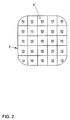
Figur 2- eine Ansicht des Ausführungsbeispiels in Richtung II der
Figur 1, Figur 3- ein Detail III der
Figur 1, und Figur 4- ein Blockschaltbild einer Steuerung für das Ausführungsbeispiel.
- Figure 1
- A schematic representation of an embodiment,
- Figure 2
- 2 shows a view of the exemplary embodiment in the direction II of FIG. 1,
- Figure 3
- a detail III of Figure 1, and
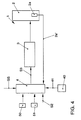
- Figure 4
- a block diagram of a controller for the embodiment.
In den Figuren 1-3 ist ein allgemein mit 1 bezeichnetes Ausführungsbeispiel einer Airbag-Vorrichtung
für ein Kraftfahrzeug dargestellt, welches sich prinzipiell in ein Gaskissen 2,
eine vorzugsweise ein- oder mehrstufige Fülleinrichtung 3 zur Erzeugung eines das
Gaskissen 2 füllenden Gases und eine die Fülleinrichtung 3 über ein Steuersignal ST
steuernde Steuereinrichtung 4, der Sensorsignale S1 eines Unfallsensors 5 zugeführt
werden, gliedert. Eine derartige Airbag-Vorrichtung 1 ist bekannt und muß daher nicht
mehr näher erläutert werden.FIGS. 1-3 show an embodiment of an airbag device, generally designated 1
shown for a motor vehicle, which is in principle in a
Wie bereits vorstehend erläutert, besteht bei einem durch den Unfallsensor 5 initiierten
Aufblasen des Gaskissens 2 der Airbag-Vorrichtung 1 die Gefahr, daß sich ein in einer
vorgelagerten Stellung, also in einer out-of-position-Situation (OOP) oder einer critical-out-of-position-Situation
(COOP) befindlicher Fahrzeuginsasse durch das sich entfaltende
Gaskissen 2 verletzt wird. Um diese Gefahr zu elimieren oder zumindest zu reduzieren, ist
bei dem beschriebenen Ausführungsbeispiel in vorteilhafter Art und Weise vorgesehen,
daß - wie am besten aus Figur 2 ersichtlich ist - an der sich auf den Insassen
zubewegenden Seite des Gaskissens 2 mindestens ein druckempfindliches
Sensorelement 10 vorgesehen ist. Stößt das Gaskissen 2 in der Entfaltungsphase auf ein
seine Entfaltung beeinträchtigendes Objekt, nämlich den in einer OOP- oder COOP-Situation
befindlichen Fahrzeuginsassen; wird ein Teilbereich der sich auf den Insassen
zubewegenden Seite 2' des Gaskissens 2 - je nach Größe und Masse dieses Objekts - an
der weiteren Ausbreitung gehindert. Die damit verbundene lokale Druckerhöhung wird
durch das oder die Sensorelemente 10 sensiert und lokalisiert. Das oder die
Sensorelemente 10 erzeugen daraufhin ein Sensorsignal S2, das zur Steuereinrichtung 4
der Airbag-Vorrichtung 1 geleitet wird.As already explained above, there is one initiated by the
Die Verwendung eines einzigen Sensorelements 10 ist prinzipiell ausreichend, um
festzustellen, daß ein Objekt die Entfaltung des Gaskissens 2 behindert. Es wird aber
bevorzugt, daß in einem definierten Bereich der sich auf den Insassen zubewegenden
Seite 2' des Gaskissens 2 eine Vielzahl von Sensorelementen 10 angeordnet sind, deren
Sensorsignale S2 der Steuereinrichtung 4 zugeführt werden. Hierdurch wird in
vorteilhafter Art und Weise eine erhöhte Auflösung erzielt, die es dann erlaubt, nicht nur
das Vorhandensein eines Objekts, sondern auch dessen Form und/oder Größe zu
sensieren. Ebenfalls kann vorgesehen sein, daß anstelle von diskreten Sensorelementen
10 an der sich auf den Insassen zubewegenden Seite des Gaskissens 2 eine Druckfolie
oder ein taktiler Sensor angeordnet sind, deren Sensorsignale S2 zur Steuereinrichtung 4
leitbar sind. Es ist auch möglich, daß zumindest in einem Teilbereich der sich auf den
Insassen zubewegenden Seite 2' des Gaskissens Drucksensoren aufgedruckt sind.In principle, the use of a
In Figur 3 ist nur eine Ausführungsform eines derartigen Sensorelements 10 dargestellt.
Das Gaskissen 2 weist hierbei einen vorzugsweise mehrlagigen Aufbau auf, um das
Sensorelement 10 thermisch vom im Innenraum des Gaskissens 2 befindlichen Gas zu
isolieren. Das Sensorelement 10 besteht hierbei aus dem eigentlichen Sensor 11, der z.B.
ein drucksensitiver Schalter oder ein Piezo-Element ist. Die von diesem Sensor 11
erzeugten Signale werden dann über entsprechende Leitungen 12a, 12b zur
Steuereinrichtung 4 geleitet.In Figure 3, only one embodiment of such a
Um nun die Zufuhr des von der Fülleinrichtung 3 erzeugten Gases zum Gaskissen 2
entsprechend steuern zu können, wird in einem ersten Schritt die Position des die
Ausbreitung des Gaskissens 2 behinderten Objekts ermittelt. Da die
Ausbreitungsgeschwindigkeit und das Ausbreitungsverhalten der sich auf den Insassen
zubewegenden Seite 2' des Gaskissens 2 bekannt und reproduzierbar sind, kann von der
Steuereinrichtung 4 zwischen dem Zündzeitpunkt der Fülleinrichtung 3 und dem von den
Sensorelementen 10 sensierten Kontaktzeitpunkt zwischen der sich auf den Insassen
zubewegenden Seite 2' des Gaskissens 2 und dem Objekt eine Abstandsbeziehung
hergestellt werden, so daß von der Steuereinrichtung 4 festgestellt werden kann, ob sich
das Objekt in COOP-Bereich, im OOP-Bereich oder im IP (in-position)-Bereich befindet.
Typischerweise findet sich ein Objekt im COOP-Bereich, wenn zwischen dem
Zündzeitpunkt der Fülleinrichtung 3 und dem Kontaktzeitpunkt eine Zeitspanne von ca. 0-5
ms liegt. Eine Position des Objekts im OOP-Bereich wird dann von der
Steuereinrichtung 4 angenommen, wenn die vorgenannte Zeitspanne im Bereich
typischerweise zwischen ca. 6 und ca. 12 ms liegt. Bei einer mehr als ca. 12 ms
dauernden Zeitspanne geht die Steuereinrichtung 4 in der Regel davon aus, daß sich das
Objekt im IP-Bereich befindet.In order to supply the gas generated by the
Stellt die Steuereinrichtung 4 nun fest, daß sich das die Ausbreitung des Gaskissens 2
behindernde Objekt im COOP-, im OOP- oder im IP-Bereich befindet, wird die
Fülleinrichtung 3 derart gesteuert, daß eine Verletzung des Fahrzeuginsassen durch das
sich entfaltende Gaskissen 2 eliminiert oder zumindest reduziert wird, indem der Zustrom
des von der Fülleinrichtung 3 erzeugten Gases zum Gaskissen 2 drastisch reduziert
und/oder unterbrochen wird (COOP-Situation), reduziert wird (OOP-Situation) oder
unvermindert aufrechterhalten wird (IP-Situation).If the
Durch die Sensierung eines hinreichend großen Kontakts zwischen der sich auf den
Insassen zubewegenden Seite 2' des Gaskissens 2 und dem Objekt während eines
einzigen Zeitpunkt ist jedoch in der Regel nicht mit hinreichender Sicherheit festzustellen,
ob es sich bei dem sensierten Objekt wirklich um den Fahrzeuginsassen handelt, der sich
in einer COOP- oder einer OOP-Situation befindet, in der eine weitere Entfaltung des
Gaskissens 2 gestoppt oder zumindest reduziert werden muß, um eine Verletzung des
Fahrzeuginsassens durch das sich entfaltende Gaskissen 2 zu vermeiden, oder ob es
sich bei dem sensierten Kontakt um einen Kontakt zwischen einem nicht dem
Fahrzeuginsassen zuzuordnenden Teil, z.B. eines infolge des Unfalls im
Fahrzeuginnenraum herumfliegenden Teiles handelt. Deshalb wird vorzugsweise
vorgesehen, daß die zeitliche Entwicklung des Kontakts zwischen der sich auf den
Insassen zubewegenden Seite 2' des Gaskissens 2 und dem Objekt registriert wird. Da
die Sensorelemente 10 an der Vorderfront 2' des Gaskissens 2 kontinuierlich, quasikontinuierlich
oder zu diskreten Zeitpunkten das Sensorsignal S2 liefern, ist die zeitliche
Entwicklung des Kontakts zwischen dem Gaskissen 2 und dem Objekt leicht zu erfassen:
Wird z.B. von der Steuereinrichtung 4 festgestellt, daß der erste Kontakt zwischen
Gaskissen und Objekt in einer Zeitspanne von ca. 0-5 ms nach Zündung der
Fülleinrichtung erfolgt, also daß sich das die Ausbreitung des Gaskissens 2 behindernde
Objekt im COOP-Bereich befindet, und hält dieser Kontakt länger als z.B. 3 ms an
und/oder vergrößert sich der sensierte Abdruck des Objekts in dieser Zeit, so wird die
Annahme, daß sich der Fahrzeuginsasse im COOP-Bereich befindet, bestätigt, so daß
dann die Fülleinrichtung 3 entsprechend abgeregelt wird.By sensing a sufficiently large contact between the one on the
Occupant-moving side 2 'of the
Ergibt jedoch die Auswertung des zeitlichen Verlaufs des sensierten Kontakts, daß der
Kontaktzustand weniger als z.B. 3 ms anhält und/oder sich der Abdruck in dieser Zeit
verkleinert, so kann davon ausgegangen werden, daß die Leistung der Fülleinrichtung 3
beibehalten oder vergrößert werden kann, ohne den Fahrzeuginsassen zu gefährden.
Entsprechende Steueralgorithmen sind auch für den OOP-Bereich möglich.However, the evaluation of the time course of the sensed contact reveals that the
Contact state less than e.g. 3 ms lasts and / or the impression changes during this time
reduced, it can be assumed that the performance of the
Vorzugsweise ist noch vorgesehen, daß - wie aus Figur 4 ersichtlich ist - in die Steuerung
der Fülleinrichtung 3 nicht nur die von den Sensorelementen 10 gelieferten Signale S2
eingehen, sondern daß auch noch weitere statische- und/oder dynamische Parameter in
die Steuerung der Fülleinrichtung 3 eingehen. Eine derartige Vorgangsweise besitzt den
Vorteil, daß hierdurch z.B. die Unfallschwere, der Gurtstatus, die Insassenmasse und/oder
die Größe des dem Fahrzeuginsassen zur Verfügung stehenden Überlebensraums mit
berücksichtigt werden. Mit Hilfe von Sensoren 50, die einen bevorstehenden Unfall oder
einen Unfall im Frühstadium erkennen, kann schon nach sehr kurzer Zeit eine qualifizierte
Aussage über die Unfallschwere getroffen werden. Der Gurtstatus GS ist ebenfalls
bekannt. Die Insassenmasse kann leicht durch unter der Sitzfläche des Sitzes
angeordnete Meßelemente 51 ermittelt werden. Mit Hilfe eines Algorithmus kann dann aus
diesen Parametern ein optimaler Einsatz der Fülleinrichtung 3 berechnet werden, z.B.
dadurch, daß dieser Algorithmus durch Vorversuche empirisch ermittelt wird.
Vorzugsweise ist dann vorgesehen, daß das von dem Sensorelement 10 gelieferte
Sensorsignal S2 während der Entfaltungsphase des Gaskissens 2 einen anderen
Kalibrierfaktor aufweist als in die Rückhaltephase, da in dieser letztgenannten Phase die
Flächenpressung höher ist als während der Entfaltungsphase, so daß die dann gelieferten
Sensorsignale S2 einen höheren Wert besitzen.It is preferably also provided that - as can be seen from FIG. 4 - into the control
the filling
Um die Verletzungsgefahr des Insassen durch den sich entfaltenden Airbag möglichst
gering zu halten, ist vorzugsweise vorgesehen, daß die Rückhaltefunktion des Gaskissens
2 der Airbag-Vorrichtung 1 derart ausgelegt ist, daß der zur Verfügung stehende
Verzögerungsweg des Insassen, also der Überlebensraum, optimal genutzt wird. Hierzu
ist vorzugsweise vorgesehen, daß der Innendruck des Gaskissens 2 in Abhängigkeit von
einer oder mehreren der im vorstehenden Absatz genannten Einflußgrößen dahingehend
gesteuert wird, daß bei geringerer Insassenmasse und/oder geringerer Unfallschwere
und/oder bei angelegtem Gurt GS der Innendruck des Gaskissens 2 der Airbag-Vorrichtung
1 nicht so hoch ist wie bei großer Insassenmasse und/oder hoher
Unfallschwere und/oder bei nicht angelegtem Gurt. Wie im vorstehenden Absatz
ausgeführt, ist hierbei die Insassenmasse ein wesentlicher Parameter. Die beschrieben
Airbag-Vorrichtung 1 erlaubt es nun, auf die bis jetzt zur Bestimmung der Insassenmasse
unter der Sitzfläche des Sitzes angeordneten Meßelemente 51 zu verzichten und die vom
Airbag zurückzuhaltenende anteilige Insassenmasse direkt über das Sensorsignal S2 des
Sensorelements 10 zu berechnen. Hierzu ist vorgesehen, daß im Kraftfahrzeug ein
Beschleunigungs-/Verzögerungssensor 40 (siehe Figur 4) angeordnet ist, welcher die
Beschleunigung/Verzögerung des Kraftfahrzeugs zumindest zum Unfallzeitpunkt mißt. Da
durch das Ausgangssignal S2 des Sensorelements 10 die vom Insassen auf das
Gaskissen 2 ausgeübte Kraft bekannt ist, kann aus der vom Sensorelement 10
gemessenen Krafteinwirkung des Insassen auf das Gaskissen 2 und der vom
Beschleunigungs-/Verzögerungssensor 40 gemessenen Beschleunigung/ Verzögerung
die zurückzuhaltende Insassenmasse berechnet werden, welche gleich dem Quotienten
von Krafteinwirkung auf das Gaskissen 2 und der Beschleunigung/ Verzögerung des
Insassen ist. Eine derartige Vorgangsweise besitzt den Vorteil, daß in die entsprechende
Regelung der Fülleinrichtung 3 das Gaskissen 2 nicht die statische, von den im Sitz
angeordneten Meßelementen 51 gemessene Insassenmasse, sondern dynamisch die
vom Gaskissen 2 aufzufangende Masse eingeht.To minimize the risk of injury to the occupant from the deploying airbag
To keep it low, it is preferably provided that the retaining function of the
Zur Steuerung der Fülleinrichtung 3 für das Gaskissen 2 der Airbag-Vorrichtung 1 ist
vorgesehen, daß der zu einem bestimmten Unfallvorgang korelierte Soll-Innendruck in der
Steuereinrichtung 4 gespeichert ist. Ein im Gaskissen 2 angeordneten Meßfüller 2a mißt
den Ist-Innendruck im Gaskissen 2. Dessen Ausgangssignal 2a' wird zur
Steuereinrichtung 4 zurückgeführt, die den vorgegebenen Soll-Wert mit dem gemessenen
Ist-Wert vergleicht und dann ein Steuersignal S3 für die Fülleinrichtung 3 erzeugt, so daß
die von der Fülleinrichtung 3 erzeugte Gasmenge entsprechend vergrößert oder
vermindert wird.To control the filling
Zusammenfassend ist festzustellen, daß die beschriebene Airbag-Vorrichtung 1 sich
dadurch auszeichnet, daß die Entfaltung und Rückhaltewirkung des Gaskissens 2 derart
gesteuert kann, daß bei einer COOP- oder bei einer OOP-Situation keine zusätzliche
Verletzungsgefahr durch die Entfaltung des Gaskissens 2 entsteht und die
Rückhaltefunktion der Airbag-Vorrichtung 1 während des gesamten Unfalles in
Abhängigkeit von der Unfallschwere, Insassenmasse und anderen Parametern steuerbar
ist. In summary, it should be noted that the
- 11
- Airbag-VorrichtungAirbag device
- 22nd
- GaskissenGas cushion
- 2'2 '
- Seitepage
- 33rd
- FülleinrichtungFilling device
- 44th
- SteuereinrichtungControl device
- 55
- UnfallsensorAccident sensor
- 1010th
- SensorelementSensor element
- 1111
- Sensorsensor
- 12a, 12b12a, 12b
- Leitungmanagement
- 4040
- Beschleunigungs-/VerzögerungssensorAcceleration / deceleration sensor
- 4141
- MeßsignalMeasurement signal
- 5050
- Sensorsensor
- 5151
- MeßelementMeasuring element
- S1S1
- SensorsignaleSensor signals
- S2S2
- SensorsignaleSensor signals
- S3S3
- SteuersignalControl signal
- STST
- SteuersignalControl signal
- GSGS
- GurtstatusBelt status
Claims (18)
Applications Claiming Priority (2)
| Application Number | Priority Date | Filing Date | Title |
|---|---|---|---|
| DE1998127135 DE19827135A1 (en) | 1998-06-18 | 1998-06-18 | Airbag device for a motor vehicle and method for controlling the same |
| DE19827135 | 1998-06-18 |
Publications (2)
| Publication Number | Publication Date |
|---|---|
| EP0965500A2 true EP0965500A2 (en) | 1999-12-22 |
| EP0965500A3 EP0965500A3 (en) | 2000-10-18 |
Family
ID=7871259
Family Applications (1)
| Application Number | Title | Priority Date | Filing Date |
|---|---|---|---|
| EP99109297A Withdrawn EP0965500A3 (en) | 1998-06-18 | 1999-05-27 | Airbag device for a vehicle and its controlling method |
Country Status (2)
| Country | Link |
|---|---|
| EP (1) | EP0965500A3 (en) |
| DE (1) | DE19827135A1 (en) |
Cited By (4)
| Publication number | Priority date | Publication date | Assignee | Title |
|---|---|---|---|---|
| EP1244579A1 (en) * | 1999-12-23 | 2002-10-02 | Z/C Holding Company | Inflatable restraint assembly for vehicles |
| EP1558468A1 (en) * | 2002-11-08 | 2005-08-03 | Key Safety Systems, Inc. | Airbag system with vehicle occupant sensor on the airbag |
| US7523956B2 (en) | 1999-12-23 | 2009-04-28 | Zumpano Bernard J | Inflatable restraint assembly for vehicles |
| CN115607865A (en) * | 2022-10-21 | 2023-01-17 | 深圳学教王科技有限公司 | Distributed quick-start emergency rescue air bag and rescue method |
Families Citing this family (6)
| Publication number | Priority date | Publication date | Assignee | Title |
|---|---|---|---|---|
| JP4163117B2 (en) * | 2001-11-17 | 2008-10-08 | フォルクスワーゲン・アクチェンゲゼルシャフト | Airbag device for vehicles, particularly for motorized vehicles |
| DE10213907C1 (en) * | 2002-03-28 | 2003-07-31 | Autoliv Dev | Automobile passenger airbag device has antenna device for HF radar unit detecting seating position of passenger provided as part of airbag |
| DE102005014603A1 (en) * | 2005-03-31 | 2006-10-05 | Conti Temic Microelectronic Gmbh | Blower device for e.g. airbag, has control device, and pressure sensor monitoring blowing process of airbag, where control device controls blowing process based on output signal from pressure sensor |
| DE102005026775A1 (en) * | 2005-06-10 | 2006-12-28 | Bayerische Motoren Werke Ag | Vehicle has restraining device, sensor device, and electronics which is a control electronics, which controls a control variable (F(t), A(t)) of restraining device depending on one measured variable |
| DE102008002243B4 (en) | 2008-06-05 | 2020-06-18 | Robert Bosch Gmbh | Method, control device and computer program product for determining an acceleration of an occupant of a vehicle |
| DE102014222035A1 (en) * | 2014-10-29 | 2016-05-04 | Bayerische Motoren Werke Aktiengesellschaft | Airbag system for a motor vehicle |
Citations (2)
| Publication number | Priority date | Publication date | Assignee | Title |
|---|---|---|---|---|
| DE19610833A1 (en) | 1995-03-22 | 1996-09-26 | Trw Vehicle Safety Systems | Control system for restraints for motor vehicle occupants |
| EP0812741A1 (en) | 1996-03-22 | 1997-12-17 | HS Technik und Design Technische Entwicklungen GmbH | Air bag device in a motor vehicle |
Family Cites Families (6)
| Publication number | Priority date | Publication date | Assignee | Title |
|---|---|---|---|---|
| DE4041049A1 (en) * | 1990-12-20 | 1992-07-02 | Siemens Ag | Control system for airbag - has processor control to inflate at rate matching severity of crash |
| DE19526334A1 (en) * | 1995-07-19 | 1997-01-23 | Bosch Gmbh Robert | Safety device for vehicle occupants |
| DE19611384C2 (en) * | 1996-03-22 | 2001-05-31 | Hs Tech & Design | Airbag device in a motor vehicle |
| DE19625730A1 (en) * | 1996-06-27 | 1998-01-02 | Teves Gmbh Alfred | Tactile sensor matrix for vehicles |
| JPH1035405A (en) * | 1996-07-18 | 1998-02-10 | Fuji Heavy Ind Ltd | Gas pressure regulating device for vehicle air bag device |
| ES2179249T3 (en) * | 1996-08-22 | 2003-01-16 | Volkswagen Ag | OCCUPANT PROTECTION DEVICE FOR A VEHICLE. |
-
1998
- 1998-06-18 DE DE1998127135 patent/DE19827135A1/en not_active Withdrawn
-
1999
- 1999-05-27 EP EP99109297A patent/EP0965500A3/en not_active Withdrawn
Patent Citations (2)
| Publication number | Priority date | Publication date | Assignee | Title |
|---|---|---|---|---|
| DE19610833A1 (en) | 1995-03-22 | 1996-09-26 | Trw Vehicle Safety Systems | Control system for restraints for motor vehicle occupants |
| EP0812741A1 (en) | 1996-03-22 | 1997-12-17 | HS Technik und Design Technische Entwicklungen GmbH | Air bag device in a motor vehicle |
Cited By (7)
| Publication number | Priority date | Publication date | Assignee | Title |
|---|---|---|---|---|
| EP1244579A1 (en) * | 1999-12-23 | 2002-10-02 | Z/C Holding Company | Inflatable restraint assembly for vehicles |
| EP1244579A4 (en) * | 1999-12-23 | 2005-10-26 | Z C Holding Company | Inflatable restraint assembly for vehicles |
| US7523956B2 (en) | 1999-12-23 | 2009-04-28 | Zumpano Bernard J | Inflatable restraint assembly for vehicles |
| EP1558468A1 (en) * | 2002-11-08 | 2005-08-03 | Key Safety Systems, Inc. | Airbag system with vehicle occupant sensor on the airbag |
| EP1558468A4 (en) * | 2002-11-08 | 2010-08-04 | Key Safety Systems Inc | Airbag system with vehicle occupant sensor on the airbag |
| CN115607865A (en) * | 2022-10-21 | 2023-01-17 | 深圳学教王科技有限公司 | Distributed quick-start emergency rescue air bag and rescue method |
| CN115607865B (en) * | 2022-10-21 | 2023-08-04 | 深圳学教王科技有限公司 | Distributed rapid-starting emergency rescue airbag and rescue method |
Also Published As
| Publication number | Publication date |
|---|---|
| EP0965500A3 (en) | 2000-10-18 |
| DE19827135A1 (en) | 1999-12-23 |
Similar Documents
| Publication | Publication Date | Title |
|---|---|---|
| EP0636074B1 (en) | Procedure and device for protecting vehicle occupants | |
| EP1122136B1 (en) | Safety device and method for restraining and occupant in a vehicle seat | |
| EP1771320B1 (en) | Motor vehicle provided with a preventatively acting security system | |
| DE69917562T2 (en) | Method and apparatus for determining the ignition timing of an occupant restraint using occupant sensor inputs | |
| DE19930384B4 (en) | Protection device for vehicle occupants | |
| EP1160134B1 (en) | Occupant restraint system | |
| DE19956530A1 (en) | Occupant restraint arrangement for motor vehicle restrains occupant with belt in event of emergency and enables safety belt to be extracted if load in excess of defined load is exerted on belt | |
| DE10123921C1 (en) | Occupant restraint system with a belt force limiting device | |
| DE19842939B4 (en) | Activation control device for a passive safety device | |
| DE102005013164B4 (en) | Method and device for controlling a passive restraint system | |
| DE102006021380A1 (en) | Vehicle occupant safety system and method for detecting the position of a vehicle occupant | |
| EP0798175A2 (en) | Method for controlling the activation of a vehicle occupant restraint system | |
| EP0965500A2 (en) | Airbag device for a vehicle and its controlling method | |
| EP1012007B1 (en) | Device for protecting occupants in an automobile and a method for controlling the inflation of a bag in an automobile | |
| DE102004038167B4 (en) | Motor vehicle with a preventive protection system | |
| EP1680311B1 (en) | Motor vehicle equipped with an occupant protection system | |
| EP0796773A2 (en) | Occupant protection system for passenger transport vehicles | |
| EP1501704A1 (en) | Method and system for actuating restraining means | |
| EP1442943B1 (en) | Pedestrian protection system and method of activation of such a system according to the impact | |
| EP0949127B1 (en) | Airbag apparatus for a vehicule and method for controlling the same to deliver a controllable quantity of gas | |
| WO2001044024A1 (en) | Adjustable restraint system for motor vehicles | |
| DE19829756C1 (en) | Trigger device for an occupant protection system | |
| DE102007015957A1 (en) | System for controlled inflation and venting of airbag which takes account of position and size of occupant and degree of impact | |
| DE19823005A1 (en) | Airbag device for a motor vehicle and method for controlling the same | |
| DE102005018979A1 (en) | Occupants restraint system for vehicle, comprising additional sensors for surveillance of wheel condition |
Legal Events
| Date | Code | Title | Description |
|---|---|---|---|
| PUAI | Public reference made under article 153(3) epc to a published international application that has entered the european phase |
Free format text: ORIGINAL CODE: 0009012 |
|
| AK | Designated contracting states |
Kind code of ref document: A2 Designated state(s): DE ES FR GB IT PT SE |
|
| AX | Request for extension of the european patent |
Free format text: AL;LT;LV;MK;RO;SI |
|
| PUAL | Search report despatched |
Free format text: ORIGINAL CODE: 0009013 |
|
| AK | Designated contracting states |
Kind code of ref document: A3 Designated state(s): AT BE CH CY DE DK ES FI FR GB GR IE IT LI LU MC NL PT SE |
|
| AX | Request for extension of the european patent |
Free format text: AL;LT;LV;MK;RO;SI |
|
| RIC1 | Information provided on ipc code assigned before grant |
Free format text: 7B 60R 21/32 A, 7B 60R 21/01 B |
|
| 17P | Request for examination filed |
Effective date: 20010418 |
|
| AKX | Designation fees paid |
Free format text: DE ES FR GB IT PT SE |
|
| 17Q | First examination report despatched |
Effective date: 20030318 |
|
| STAA | Information on the status of an ep patent application or granted ep patent |
Free format text: STATUS: THE APPLICATION HAS BEEN WITHDRAWN |
|
| 18W | Application withdrawn |
Effective date: 20030701 |