EP0964179B1 - Arrangement d'une masse dans un conteneur - Google Patents
Arrangement d'une masse dans un conteneur Download PDFInfo
- Publication number
- EP0964179B1 EP0964179B1 EP99113994A EP99113994A EP0964179B1 EP 0964179 B1 EP0964179 B1 EP 0964179B1 EP 99113994 A EP99113994 A EP 99113994A EP 99113994 A EP99113994 A EP 99113994A EP 0964179 B1 EP0964179 B1 EP 0964179B1
- Authority
- EP
- European Patent Office
- Prior art keywords
- mass
- container
- damper
- damping
- fluid
- Prior art date
- Legal status (The legal status is an assumption and is not a legal conclusion. Google has not performed a legal analysis and makes no representation as to the accuracy of the status listed.)
- Expired - Lifetime
Links
Images
Classifications
-
- F—MECHANICAL ENGINEERING; LIGHTING; HEATING; WEAPONS; BLASTING
- F16—ENGINEERING ELEMENTS AND UNITS; GENERAL MEASURES FOR PRODUCING AND MAINTAINING EFFECTIVE FUNCTIONING OF MACHINES OR INSTALLATIONS; THERMAL INSULATION IN GENERAL
- F16F—SPRINGS; SHOCK-ABSORBERS; MEANS FOR DAMPING VIBRATION
- F16F7/00—Vibration-dampers; Shock-absorbers
- F16F7/10—Vibration-dampers; Shock-absorbers using inertia effect
- F16F7/104—Vibration-dampers; Shock-absorbers using inertia effect the inertia member being resiliently mounted
- F16F7/112—Vibration-dampers; Shock-absorbers using inertia effect the inertia member being resiliently mounted on fluid springs
-
- F—MECHANICAL ENGINEERING; LIGHTING; HEATING; WEAPONS; BLASTING
- F16—ENGINEERING ELEMENTS AND UNITS; GENERAL MEASURES FOR PRODUCING AND MAINTAINING EFFECTIVE FUNCTIONING OF MACHINES OR INSTALLATIONS; THERMAL INSULATION IN GENERAL
- F16F—SPRINGS; SHOCK-ABSORBERS; MEANS FOR DAMPING VIBRATION
- F16F7/00—Vibration-dampers; Shock-absorbers
- F16F7/10—Vibration-dampers; Shock-absorbers using inertia effect
- F16F7/104—Vibration-dampers; Shock-absorbers using inertia effect the inertia member being resiliently mounted
- F16F7/116—Vibration-dampers; Shock-absorbers using inertia effect the inertia member being resiliently mounted on metal springs
-
- F—MECHANICAL ENGINEERING; LIGHTING; HEATING; WEAPONS; BLASTING
- F16—ENGINEERING ELEMENTS AND UNITS; GENERAL MEASURES FOR PRODUCING AND MAINTAINING EFFECTIVE FUNCTIONING OF MACHINES OR INSTALLATIONS; THERMAL INSULATION IN GENERAL
- F16F—SPRINGS; SHOCK-ABSORBERS; MEANS FOR DAMPING VIBRATION
- F16F2230/00—Purpose; Design features
- F16F2230/0052—Physically guiding or influencing
Definitions
- the present invention relates to an apparatus according to the preamble of claim 1 and more particularly to dampers which may find use in reducing the periodic motion of elongated structures such as booms.
- the invention may have particular utility with booms mounted on satellites to hold measuring equipment, the accuracy of which may be reduced due to the sway of the boom resulting from disturbances such as thermal distortion shock caused by, for example, transient thermal distortions of solar panels.
- the present invention provides apparatus as defined in Claim 1.
- the apparatus comprises the features of any one or more of dependent Claims 2 to 4.
- the present invention may overcome the problems in the prior art by providing a damper with a mass which is constrained to move in the desired direction.
- a damper with a mass which is constrained to move in the desired direction.
- the fluid may be varied to make the vibration tunable and, in fact, provides for tunable damping without having to change the fluid.
- the tuning of the damping is accomplished by providing a pair of bellows with changeable internal springs therein to change the volumetric stiffness of the bellows and thus provide different characteristics to the fluid expansion and contraction in the chambers surrounding the mass.
- only the springs internal to the bellows need be changed for fine tuning.
- a nearly frictionless motion is provided by using a linear bearing with, for example, circulating balls.
- a specific improvement to the ball bearing mounting is shown in the present invention by the use of a plurality of linear troughs in the mass, each of which entraps a single ball so that there is no sliding friction between the mass and the walls or between adjacent balls.
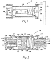
- a damper 8 comprising a hollow moveable mass 10, slideably mounted in a cylindrical container 12 having a first end piece 14 fastened to cylinder 12 by conventional means, such as bolts, not shown and sealed to prevent fluid loss by a grommet 16.
- a second end piece 18 is fastened at a second end in a recess 20 of cylinder 12 by conventional means such as bolts, also not shown.
- the cylinder 12 and end pieces 14 and 18 form a chamber 22 within which mass 10 may move back and forth.
- a spring 30 of predetermined stiffness is fastened at one end thereof to a protrusion 32 of end piece 14 and at the other end thereof to a recess 34 in mass 10 so that mass 10 will be positioned by spring 30 until subjected to a force allowing mass 10 to oscillate, only horizontally, back and forth in chamber 22 at a frequency determined by the size of mass 10 and stiffness of spring 30.
- the first end piece 14 has a filling port 36 therethrough which allows the introduction of a damping fluid, shown by arrow 38, into the chamber 22. After filling, port 36 is sealed in conventional manner.
- a thermal expansion bellows 40 is connected at one end thereof to a protrusion 42 in end piece 18 and at the other end thereof to a sealing member 44.
- End piece 18 has a small opening 48 therethrough connecting the interior of bellows 40 to chamber 22. This allows transfer of fluid from chamber 22 to the interior of bellows 40 to accommodate expansion and contraction of the fluid under modest temperature variations.
- the damper may be used to compensate for unwanted vibrations of, for example, a boom shown in Figure 1 by reference numeral 50.
- the unwanted oscillations will be transverse to the length of the boom and accordingly it is desired that the mass 10 move in the same direction, i.e. from right to left in Figure 1.
- the damper 8 is shown mounted to boom 59 horizontally as indicated by dashed lines 52 and 54 and, as explained above, will vibrate 180 degrees out of phase with the boom to help cancel the boom motion.
- the apparatus of Figure 1 will perform satisfactorily, but for some high accuracy or specialized uses, there may be inaccuracies or unnecessary costs associated with the Figure 1 damper.
- the damping fluid 38 in chamber 20 is first chosen to have a viscosity which is believed to provide the best absorption of energy from the oscillating system and provide the desired amount of damping for the specific intended use.
- the boom and the damper are then tested to check the damping characteristics and, if they are not right, the fluid has to be drained and new fluid with different viscosity inserted for a re-test. This process is repeated until the desired damping characteristics of the system are obtained.
- Such a procedure is quite costly and time consuming and adds considerable cost to the damper.
- a damper 108 (which may also be attached to a beam as in Figure 1 but not shown in Figure 2 for simplicity) is shown comprising a moveable mass 110, slideably mounted in a cylindrical container 112 having a first cylindrical end piece 114 fastened to the right end of cylinder 112 by conventional means, not shown.
- a spring 116 has a first end fastened in a recess 118 of mass 112 and a second end fastened to end piece 114 so that mass 110 is positioned thereby.
- Mass 110 is shown having an orifice 120 extending between its left and right sides in Figure 2 so as to permit the passage of the damping fluid therethrough.
- the damping fluid may be inserted in the cylindrical container 112 in a manner similar to that shown in Figure 1.
- the mass 110 and the spring 116 are chosen to have the frequency of oscillation matching the particular use to which it is to be put e.g. the frequency of the boom to which it will be mounted.
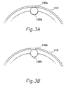
- a plurality of troughs 122, 124, 126 and 128 are shown in the outer edge of mass 110 and are cross-sectionally shaped to constrain the movement of balls such as 132, 134, 136 and 138 in all but the desired direction, horizontally in Figure 2.
- the grooves may be of slightly greater diameter than the balls as is shown in Figure 3a where a semicircular groove 122a supports the ball 132a, or, as shown in Figure 3b, may be a "V" shaped groove 122b supporting a ball 132b. In either case, the ball is constrained for motion only into and out of the plane of the paper.
- the plurality of balls 132, 134, 136 and 138 in the troughs 122, 124, 126 and 128 respectively engage the inner surface of cylinder 112 and provide rolling motion for mass 110.
- the lengths of the troughs are made to accommodate the amount of motion expected of mass 110 oscillating back and forth in use.
- the balls may nevertheless reach the ends of the trough where they may encounter greater friction due to the worming effect and/or tolerance errors.
- the device is completely self centering so that when the motion decreases to the expected limits, the balls will move to the center and at rest assume the position shown in Figure 2.
- Cylindrical end piece 114 has an abutment 140 and a first cylindrical end member 142 is seated thereon.
- Cylindrical end member 142 has an inwardly extending ledge 144 and a removable end cap 146 with a hole 148 extending centrally therethrough.
- End cap 146 is mounted against ledge 144.
- a first bellows 150 has a right end which is fixed to the ledge 144 and extends to the left towards the interior of cylindrical container 112. The left end of bellows 150 is sealed to a circular plate 152 which has a central rod 154 extending back to the right so as to be guided in the hole 148.
- a spring 156 is positioned in the interior of bellows 150 between the circular plate 152 and the end cap 146 and provides additional volumetric stiffness to the bellows 150.
- the left end of damper 108 in Figure 2 is similar to the right end.
- a second cylindrical end piece 164 is fastened to the left end of cylindrical container 112 by conventional means, not shown.
- End piece 164 has an abutment 166 and a second cylindrical end member 168 is seated thereon.
- Cylindrical end member 168 has an inwardly extending ledge 170 and a removable end cap 172 with a hole 174 extending therethrough.
- End cap 172 is mounted against ledge 170.
- a second bellows 180 has a left end which is fixed to the ledge 170 and extends to the right towards the interior of cylindrical container 112.
- bellows 180 The right end of bellows 180 is sealed to a circular plate 182 which has a central rod 184 extending back to the left so as to be guided in the hole 174.
- a spring 186 is positioned in the interior of bellows 180 between the circular plate 182 and the end cap 172 and provides additional volumetric stiffness to the bellows 180.
- the first and second bellows may be omitted and a single temperature compensating bellows such as shown in Figure 1 employed.
- two dampers mounted on the member at right angles to each other may be employed.
Landscapes
- Engineering & Computer Science (AREA)
- General Engineering & Computer Science (AREA)
- Mechanical Engineering (AREA)
- Vibration Prevention Devices (AREA)
Claims (4)
- Arrangement d'une masse (110) ayant une surface extérieure, dans un conteneur (112) ayant une surface intérieure, la masse oscillant dans ledit conteneur et une pluralité de creux (122 à 128) étant formée dans la surface de la masse (112) autour de sa périphérie,
caractérisé par des moyens pour minimiser la friction entre ladite masse et ledit conteneur, comprenant :une pluralité de billes (132 à 138), une positionnée dans chaque creux et portant contre la surface intérieure du conteneur pour permettre l'oscillation avec une faible friction de la masse dans le conteneur. - Arrangement selon la revendication 1, caractérisé en ce qu'au moins trois creux sont espacés autour de la périphérie de la masse à chaque extrémité de celle-ci.
- Arrangement selon la revendication 2, caractérisé en ce que le conteneur et la masse comprennent un amortisseur (8) utilisé dans l'amortissement du mouvement oscillatoire d'un élément auquel l'amortisseur est fixé.
- Arrangement selon la revendication 3, caractérisé en outre par un fluide de viscosité prédéterminée dans le conteneur de chaque côté de la masse.
Applications Claiming Priority (3)
| Application Number | Priority Date | Filing Date | Title |
|---|---|---|---|
| US08/591,922 US5873438A (en) | 1996-01-25 | 1996-01-25 | Tuned mass damper with tunable damping and anti friction rolling mass |
| US591922 | 1996-01-25 | ||
| EP96939697A EP0871826B1 (fr) | 1996-01-25 | 1996-11-13 | Amortisseur a masse accordee dote d'une masse a amortissement accordable et roulement antifrottement |
Related Parent Applications (1)
| Application Number | Title | Priority Date | Filing Date |
|---|---|---|---|
| EP96939697A Division EP0871826B1 (fr) | 1996-01-25 | 1996-11-13 | Amortisseur a masse accordee dote d'une masse a amortissement accordable et roulement antifrottement |
Publications (2)
| Publication Number | Publication Date |
|---|---|
| EP0964179A1 EP0964179A1 (fr) | 1999-12-15 |
| EP0964179B1 true EP0964179B1 (fr) | 2003-04-16 |
Family
ID=24368518
Family Applications (2)
| Application Number | Title | Priority Date | Filing Date |
|---|---|---|---|
| EP96939697A Expired - Lifetime EP0871826B1 (fr) | 1996-01-25 | 1996-11-13 | Amortisseur a masse accordee dote d'une masse a amortissement accordable et roulement antifrottement |
| EP99113994A Expired - Lifetime EP0964179B1 (fr) | 1996-01-25 | 1996-11-13 | Arrangement d'une masse dans un conteneur |
Family Applications Before (1)
| Application Number | Title | Priority Date | Filing Date |
|---|---|---|---|
| EP96939697A Expired - Lifetime EP0871826B1 (fr) | 1996-01-25 | 1996-11-13 | Amortisseur a masse accordee dote d'une masse a amortissement accordable et roulement antifrottement |
Country Status (5)
| Country | Link |
|---|---|
| US (2) | US5873438A (fr) |
| EP (2) | EP0871826B1 (fr) |
| JP (2) | JP2000504087A (fr) |
| DE (2) | DE69627546T2 (fr) |
| WO (1) | WO1997027408A1 (fr) |
Families Citing this family (41)
| Publication number | Priority date | Publication date | Assignee | Title |
|---|---|---|---|---|
| US5816373A (en) * | 1997-03-21 | 1998-10-06 | Honeywell Inc. | Pneumatic tuned mass damper |
| US5979882A (en) * | 1997-11-22 | 1999-11-09 | Honeywell Inc. | Direct fluid shear damper |
| US6292967B1 (en) | 1999-09-14 | 2001-09-25 | Construction Technology Laboratories, Inc. | TMD-damped stay cable and method and TMD |
| AU2003205138A1 (en) | 2002-01-15 | 2003-07-30 | Honeywell International Inc. | Tuned mass damper using a hexapod |
| US6634472B1 (en) | 2002-04-03 | 2003-10-21 | Toren S. Davis | Tuned mass damper with translational axis damping |
| JP4012024B2 (ja) * | 2002-09-10 | 2007-11-21 | キヤノン株式会社 | 位置決め装置に於ける衝撃吸収装置 |
| TWI225452B (en) * | 2003-05-26 | 2004-12-21 | Yi-Hsung Pang | Braking buffer and turning balance apparatus for motor car |
| US7073865B2 (en) * | 2003-07-03 | 2006-07-11 | Lear Corporation | Tuned vibration absorbing system for a seat system |
| FI119655B (fi) * | 2003-10-20 | 2009-01-30 | Waertsilae Finland Oy | Värähtelyn vaimennin ja moottorin värähtelyn vaimennusjärjestely |
| US20050121896A1 (en) * | 2003-12-04 | 2005-06-09 | Robert Bonhard | Torsional dynamic tuned absorber for vehicle steering system |
| US7121729B2 (en) * | 2004-03-15 | 2006-10-17 | Honeywell International, Inc. | Damped bearing cage |
| US20050217954A1 (en) * | 2004-03-31 | 2005-10-06 | Hindle Timothy A | Viscous isolation and damping strut utilizing a fluid mass effect |
| JP4782592B2 (ja) * | 2005-03-22 | 2011-09-28 | 東洋ゴム工業株式会社 | 防振装置 |
| US20060243549A1 (en) * | 2005-04-28 | 2006-11-02 | Honeywell International, Inc. | Magnetic bearings for damping and/or isolation systems |
| DE102007037048A1 (de) * | 2007-08-06 | 2009-02-12 | Robert Bosch Gmbh | Zusatzhandgriffvorrichtung |
| US8261896B2 (en) * | 2008-09-18 | 2012-09-11 | Honeywell International Inc. | Tuned mass dampers and vibration isolation apparatus |
| CN101492941B (zh) * | 2008-12-26 | 2011-03-16 | 中铁大桥局集团武汉桥梁科学研究院有限公司 | 一种液体质量双调谐减振方法 |
| US8272786B2 (en) | 2009-02-18 | 2012-09-25 | Honeywell International Inc. | Vibration isolation mounting assembly |
| US8256750B2 (en) * | 2009-02-18 | 2012-09-04 | Honeywell International Inc. | Vibration isolation mounting assembly |
| JP2010264785A (ja) * | 2009-05-12 | 2010-11-25 | Kanto Auto Works Ltd | 車両用ドア開閉装置 |
| US8327985B2 (en) * | 2009-06-22 | 2012-12-11 | Honeywell International Inc. | Two stage vibration isolator |
| US20110193277A1 (en) * | 2010-01-08 | 2011-08-11 | University Of Connecticut | Smart Vibration Absorber For Traffic Signal Supports |
| US8702377B2 (en) | 2010-06-23 | 2014-04-22 | Honeywell International Inc. | Gas turbine engine rotor tip clearance and shaft dynamics system and method |
| US8726762B2 (en) | 2010-06-28 | 2014-05-20 | Honeywell International Inc. | Tunable mass damper for use with a reaction wheel assembly |
| DE102011007725A1 (de) * | 2011-04-20 | 2012-10-25 | Hilti Aktiengesellschaft | Handwerkzeugmaschine und Tilger |
| CN103835384A (zh) * | 2013-12-30 | 2014-06-04 | 同济大学 | 质量调谐减振装置 |
| US9587702B2 (en) | 2014-02-18 | 2017-03-07 | Honeywell International Inc. | Vibration isolator using externally pressurized sealing bellows and an external shaft |
| CN104389943B (zh) * | 2014-09-12 | 2017-06-06 | 上海卫星工程研究所 | 一种卫星用液体阻尼隔振器 |
| CN104455182A (zh) * | 2014-11-21 | 2015-03-25 | 上海卫星工程研究所 | 卫星用液体阻尼隔振器 |
| EP3436718A4 (fr) | 2016-03-28 | 2019-11-27 | Robert Berry | Système et procédé de masse accordée perturbatrice |
| DE102016107765A1 (de) | 2016-04-27 | 2017-11-02 | Karlsruher Institut für Technologie | Schwingungsdämpfer |
| US9992890B1 (en) * | 2016-12-07 | 2018-06-05 | Raytheon Company | Modules and systems for damping excitations within fluid-filled structures |
| CN106948256B (zh) * | 2017-04-26 | 2019-06-21 | 中铁大桥科学研究院有限公司 | 一种超低频液体质量调谐阻尼器及设计方法 |
| US10041558B1 (en) | 2017-10-06 | 2018-08-07 | Topline Corporation | Tunable apparatus for adjusting effective performance of particle impact damper |
| US10021779B1 (en) | 2017-11-28 | 2018-07-10 | TopLine Coporation | Quick response particle damper for printed circuit boards and planar surfaces |
| JP7019476B2 (ja) * | 2018-03-26 | 2022-02-15 | 日立Astemo株式会社 | ダンパ装置 |
| US10704639B2 (en) | 2018-08-14 | 2020-07-07 | Topline Corporation | Unidirectional particle damper for printed circuit boards and planar surfaces |
| EP3640496A1 (fr) * | 2018-10-18 | 2020-04-22 | Siemens Aktiengesellschaft | Amortisseur de vibrations actif pouvant être inséré dans des orientations multiples |
| CN110410611A (zh) * | 2019-07-26 | 2019-11-05 | 武汉地震工程研究院有限公司 | 一种建筑管道结构摩擦调谐减震装置 |
| US11401993B1 (en) * | 2020-09-17 | 2022-08-02 | The United States Of America As Represented By The Secretary Of The Navy | Shock mitigation utilizing quiescent cavitation |
| CN113639004B (zh) * | 2021-08-24 | 2022-05-27 | 上海大学 | 一种挤压模式巨电流变液阻尼器 |
Family Cites Families (14)
| Publication number | Priority date | Publication date | Assignee | Title |
|---|---|---|---|---|
| US965838A (en) * | 1910-06-01 | 1910-07-26 | Andrew F Sanborn Jr | Spring-support for hammocks. |
| US2225929A (en) * | 1938-02-28 | 1940-12-24 | Sarazin Raoul Roland Raymond | Vibration damper |
| US2605099A (en) * | 1949-01-07 | 1952-07-29 | Firestone Tire & Rubber Co | Rubber-metal spring |
| US2586043A (en) * | 1950-10-14 | 1952-02-19 | Northrop Aircraft Inc | Kinetic boom damper |
| US3091307A (en) * | 1961-10-16 | 1963-05-28 | Univ Kansas State | Impact vibration damper and control means therefor |
| DE1303088B (fr) * | 1963-07-05 | Sumitomo Metal Industries Ltd | ||
| US3749109A (en) * | 1971-10-22 | 1973-07-31 | Robertshaw Controls Co | Self-contained relay module unit and system utilizing the same |
| GB1440388A (en) * | 1973-09-07 | 1976-06-23 | Woodhead Ltd Jonas | Impact absorbers |
| US3911199A (en) * | 1974-04-26 | 1975-10-07 | Westinghouse Electric Corp | Seismic motion-damper for upstanding electrical equipment |
| US4530518A (en) * | 1982-01-18 | 1985-07-23 | Newton Alan R | Vehicle stabilizer |
| DE3244997A1 (de) * | 1982-12-04 | 1984-06-14 | Festo-Maschinenfabrik Gottlieb Stoll, 7300 Esslingen | Stossdaempfer |
| JPS6023646A (ja) * | 1983-07-18 | 1985-02-06 | Jgc Corp | 防振装置 |
| JPH01309886A (ja) * | 1988-02-12 | 1989-12-14 | Yamaha Motor Co Ltd | 自動二輪車の操舵装置 |
| US4935838A (en) * | 1988-08-25 | 1990-06-19 | Westinghouse Electric Corp. | Structural magnetic vibration controller and method for actively controlling vibrations on stationary components of rotary machinery |
-
1996
- 1996-01-25 US US08/591,922 patent/US5873438A/en not_active Expired - Lifetime
- 1996-11-13 DE DE69627546T patent/DE69627546T2/de not_active Expired - Lifetime
- 1996-11-13 JP JP9526826A patent/JP2000504087A/ja active Pending
- 1996-11-13 EP EP96939697A patent/EP0871826B1/fr not_active Expired - Lifetime
- 1996-11-13 DE DE69611624T patent/DE69611624T2/de not_active Expired - Lifetime
- 1996-11-13 EP EP99113994A patent/EP0964179B1/fr not_active Expired - Lifetime
- 1996-11-13 WO PCT/US1996/018224 patent/WO1997027408A1/fr active IP Right Grant
-
1998
- 1998-09-16 US US09/153,951 patent/US6454063B1/en not_active Expired - Lifetime
-
2008
- 2008-07-01 JP JP2008172311A patent/JP4524319B2/ja not_active Expired - Fee Related
Also Published As
| Publication number | Publication date |
|---|---|
| EP0871826B1 (fr) | 2001-01-17 |
| JP2000504087A (ja) | 2000-04-04 |
| DE69627546T2 (de) | 2004-01-15 |
| US6454063B1 (en) | 2002-09-24 |
| WO1997027408A1 (fr) | 1997-07-31 |
| JP4524319B2 (ja) | 2010-08-18 |
| EP0871826A1 (fr) | 1998-10-21 |
| DE69611624D1 (de) | 2001-02-22 |
| DE69611624T2 (de) | 2001-05-03 |
| US5873438A (en) | 1999-02-23 |
| DE69627546D1 (de) | 2003-05-22 |
| EP0964179A1 (fr) | 1999-12-15 |
| JP2008232446A (ja) | 2008-10-02 |
Similar Documents
| Publication | Publication Date | Title |
|---|---|---|
| EP0964179B1 (fr) | Arrangement d'une masse dans un conteneur | |
| EP0968379B1 (fr) | Amortisseur a masse syntonisee pneumatique | |
| KR100269034B1 (ko) | 자기조정형진동감쇄장치 | |
| US6634472B1 (en) | Tuned mass damper with translational axis damping | |
| US5219051A (en) | Folded viscous damper | |
| US4778037A (en) | Vibration or shock isolators with tension and compression springs arranged equiangularly in a rosette | |
| US5070663A (en) | Damping device for tower-like structure | |
| US6435470B1 (en) | Tunable vibration noise reducer with spherical element containing tracks | |
| CA2296673A1 (fr) | Dispositif d'isolation pneumatique | |
| EP0274802B1 (fr) | Isolateur contre les vibrations ou chocs | |
| US2534963A (en) | Nutation damper for gyroscopes | |
| US5433302A (en) | Accessible variable tuned damper assembly for optical table tops | |
| SU1176364A1 (ru) | Установка дл демонстрации колебаний транспортного средства | |
| SU1301948A1 (ru) | Динамический гаситель колебаний ма тникового типа | |
| RU2289739C1 (ru) | Адаптивный динамический гаситель колебаний вращающихся тел | |
| RU2295074C1 (ru) | Динамический гаситель колебаний вращающихся тел | |
| SU979752A1 (ru) | Амортизатор | |
| RU2023818C1 (ru) | Виброизолированный фундамент | |
| RU1772458C (ru) | Виброизол тор | |
| SU892050A1 (ru) | Гаситель колебаний | |
| SU1474356A1 (ru) | Демпфирующее покрытие | |
| SU1138615A1 (ru) | Микрокриогенна система | |
| JP2002188683A (ja) | 受動式制振装置 | |
| JPH0861428A (ja) | 除振装置 | |
| JPH10231877A (ja) | 衝撃吸収装置 |
Legal Events
| Date | Code | Title | Description |
|---|---|---|---|
| PUAI | Public reference made under article 153(3) epc to a published international application that has entered the european phase |
Free format text: ORIGINAL CODE: 0009012 |
|
| 17P | Request for examination filed |
Effective date: 19990727 |
|
| AC | Divisional application: reference to earlier application |
Ref document number: 871826 Country of ref document: EP |
|
| AK | Designated contracting states |
Kind code of ref document: A1 Designated state(s): DE FR GB |
|
| RIN1 | Information on inventor provided before grant (corrected) |
Inventor name: JOHNSON, CONOR Inventor name: DAVIS, TOREN S. Inventor name: OSTERBERG, DAVID A. |
|
| AKX | Designation fees paid |
Free format text: DE FR GB |
|
| 17Q | First examination report despatched |
Effective date: 20020103 |
|
| GRAH | Despatch of communication of intention to grant a patent |
Free format text: ORIGINAL CODE: EPIDOS IGRA |
|
| GRAH | Despatch of communication of intention to grant a patent |
Free format text: ORIGINAL CODE: EPIDOS IGRA |
|
| GRAA | (expected) grant |
Free format text: ORIGINAL CODE: 0009210 |
|
| AC | Divisional application: reference to earlier application |
Ref document number: 0871826 Country of ref document: EP Kind code of ref document: P |
|
| AK | Designated contracting states |
Designated state(s): DE FR GB |
|
| REG | Reference to a national code |
Ref country code: GB Ref legal event code: FG4D |
|
| REF | Corresponds to: |
Ref document number: 69627546 Country of ref document: DE Date of ref document: 20030522 Kind code of ref document: P |
|
| ET | Fr: translation filed | ||
| PLBE | No opposition filed within time limit |
Free format text: ORIGINAL CODE: 0009261 |
|
| STAA | Information on the status of an ep patent application or granted ep patent |
Free format text: STATUS: NO OPPOSITION FILED WITHIN TIME LIMIT |
|
| 26N | No opposition filed |
Effective date: 20040119 |
|
| PGFP | Annual fee paid to national office [announced via postgrant information from national office to epo] |
Ref country code: GB Payment date: 20051004 Year of fee payment: 10 |
|
| GBPC | Gb: european patent ceased through non-payment of renewal fee |
Effective date: 20061113 |
|
| PG25 | Lapsed in a contracting state [announced via postgrant information from national office to epo] |
Ref country code: GB Free format text: LAPSE BECAUSE OF NON-PAYMENT OF DUE FEES Effective date: 20061113 |
|
| PGFP | Annual fee paid to national office [announced via postgrant information from national office to epo] |
Ref country code: DE Payment date: 20121130 Year of fee payment: 17 |
|
| PG25 | Lapsed in a contracting state [announced via postgrant information from national office to epo] |
Ref country code: DE Free format text: LAPSE BECAUSE OF NON-PAYMENT OF DUE FEES Effective date: 20140603 |
|
| REG | Reference to a national code |
Ref country code: DE Ref legal event code: R119 Ref document number: 69627546 Country of ref document: DE Effective date: 20140603 |
|
| REG | Reference to a national code |
Ref country code: FR Ref legal event code: PLFP Year of fee payment: 20 |
|
| PGFP | Annual fee paid to national office [announced via postgrant information from national office to epo] |
Ref country code: FR Payment date: 20151027 Year of fee payment: 20 |
|
| P01 | Opt-out of the competence of the unified patent court (upc) registered |
Effective date: 20230525 |