EP0964175A2 - Hydrodynamisches Gaslager und Verfahren zur Herstellung eines solchen Lagers - Google Patents
Hydrodynamisches Gaslager und Verfahren zur Herstellung eines solchen Lagers Download PDFInfo
- Publication number
- EP0964175A2 EP0964175A2 EP99304524A EP99304524A EP0964175A2 EP 0964175 A2 EP0964175 A2 EP 0964175A2 EP 99304524 A EP99304524 A EP 99304524A EP 99304524 A EP99304524 A EP 99304524A EP 0964175 A2 EP0964175 A2 EP 0964175A2
- Authority
- EP
- European Patent Office
- Prior art keywords
- shaft body
- outer periphery
- hollow portion
- gas bearing
- cross
- Prior art date
- Legal status (The legal status is an assumption and is not a legal conclusion. Google has not performed a legal analysis and makes no representation as to the accuracy of the status listed.)
- Withdrawn
Links
- 238000004519 manufacturing process Methods 0.000 title claims description 17
- 230000002093 peripheral effect Effects 0.000 claims abstract description 47
- 230000008859 change Effects 0.000 claims description 4
- 238000003825 pressing Methods 0.000 claims description 4
- 230000004913 activation Effects 0.000 abstract description 2
- 238000012545 processing Methods 0.000 description 19
- 238000000034 method Methods 0.000 description 8
- 239000000463 material Substances 0.000 description 7
- 238000012360 testing method Methods 0.000 description 7
- 238000005259 measurement Methods 0.000 description 6
- 239000003921 oil Substances 0.000 description 4
- 230000002706 hydrostatic effect Effects 0.000 description 3
- 229910052581 Si3N4 Inorganic materials 0.000 description 2
- 230000015572 biosynthetic process Effects 0.000 description 2
- 239000000919 ceramic Substances 0.000 description 2
- 230000000052 comparative effect Effects 0.000 description 2
- 238000005520 cutting process Methods 0.000 description 2
- 230000007423 decrease Effects 0.000 description 2
- 230000000694 effects Effects 0.000 description 2
- HQVNEWCFYHHQES-UHFFFAOYSA-N silicon nitride Chemical compound N12[Si]34N5[Si]62N3[Si]51N64 HQVNEWCFYHHQES-UHFFFAOYSA-N 0.000 description 2
- 229910001220 stainless steel Inorganic materials 0.000 description 2
- 239000010935 stainless steel Substances 0.000 description 2
- 230000007704 transition Effects 0.000 description 2
- 238000004458 analytical method Methods 0.000 description 1
- 230000015556 catabolic process Effects 0.000 description 1
- 230000006835 compression Effects 0.000 description 1
- 238000007906 compression Methods 0.000 description 1
- 238000007796 conventional method Methods 0.000 description 1
- 230000003247 decreasing effect Effects 0.000 description 1
- 238000006731 degradation reaction Methods 0.000 description 1
- 230000001419 dependent effect Effects 0.000 description 1
- 239000000314 lubricant Substances 0.000 description 1
- 230000008569 process Effects 0.000 description 1
- 238000003672 processing method Methods 0.000 description 1
- 239000007787 solid Substances 0.000 description 1
- 230000001629 suppression Effects 0.000 description 1
Images




Classifications
-
- F—MECHANICAL ENGINEERING; LIGHTING; HEATING; WEAPONS; BLASTING
- F16—ENGINEERING ELEMENTS AND UNITS; GENERAL MEASURES FOR PRODUCING AND MAINTAINING EFFECTIVE FUNCTIONING OF MACHINES OR INSTALLATIONS; THERMAL INSULATION IN GENERAL
- F16C—SHAFTS; FLEXIBLE SHAFTS; ELEMENTS OR CRANKSHAFT MECHANISMS; ROTARY BODIES OTHER THAN GEARING ELEMENTS; BEARINGS
- F16C17/00—Sliding-contact bearings for exclusively rotary movement
- F16C17/02—Sliding-contact bearings for exclusively rotary movement for radial load only
- F16C17/028—Sliding-contact bearings for exclusively rotary movement for radial load only with fixed wedges to generate hydrodynamic pressure, e.g. multi-lobe bearings
-
- F—MECHANICAL ENGINEERING; LIGHTING; HEATING; WEAPONS; BLASTING
- F16—ENGINEERING ELEMENTS AND UNITS; GENERAL MEASURES FOR PRODUCING AND MAINTAINING EFFECTIVE FUNCTIONING OF MACHINES OR INSTALLATIONS; THERMAL INSULATION IN GENERAL
- F16C—SHAFTS; FLEXIBLE SHAFTS; ELEMENTS OR CRANKSHAFT MECHANISMS; ROTARY BODIES OTHER THAN GEARING ELEMENTS; BEARINGS
- F16C33/00—Parts of bearings; Special methods for making bearings or parts thereof
- F16C33/02—Parts of sliding-contact bearings
- F16C33/04—Brasses; Bushes; Linings
- F16C33/06—Sliding surface mainly made of metal
- F16C33/10—Construction relative to lubrication
- F16C33/1005—Construction relative to lubrication with gas, e.g. air, as lubricant
- F16C33/101—Details of the bearing surface, e.g. means to generate pressure such as lobes or wedges
-
- Y—GENERAL TAGGING OF NEW TECHNOLOGICAL DEVELOPMENTS; GENERAL TAGGING OF CROSS-SECTIONAL TECHNOLOGIES SPANNING OVER SEVERAL SECTIONS OF THE IPC; TECHNICAL SUBJECTS COVERED BY FORMER USPC CROSS-REFERENCE ART COLLECTIONS [XRACs] AND DIGESTS
- Y10—TECHNICAL SUBJECTS COVERED BY FORMER USPC
- Y10T—TECHNICAL SUBJECTS COVERED BY FORMER US CLASSIFICATION
- Y10T29/00—Metal working
- Y10T29/49—Method of mechanical manufacture
- Y10T29/49636—Process for making bearing or component thereof
- Y10T29/49639—Fluid bearing
-
- Y—GENERAL TAGGING OF NEW TECHNOLOGICAL DEVELOPMENTS; GENERAL TAGGING OF CROSS-SECTIONAL TECHNOLOGIES SPANNING OVER SEVERAL SECTIONS OF THE IPC; TECHNICAL SUBJECTS COVERED BY FORMER USPC CROSS-REFERENCE ART COLLECTIONS [XRACs] AND DIGESTS
- Y10—TECHNICAL SUBJECTS COVERED BY FORMER USPC
- Y10T—TECHNICAL SUBJECTS COVERED BY FORMER US CLASSIFICATION
- Y10T82/00—Turning
- Y10T82/10—Process of turning
Definitions
- the present invention generally relates to a hydrodynamic gas bearing and manufactuiing method thereof.
- the present invention relates to a hydrodynamic gas bearing supporting a rotator rotating at a high speed and a manufacturing method thereof.
- a gas bearing has been known as a bearing allowing high speed rotation, in which a shaft body and a bearing body are supported in non-contact manner by means of gas such as air.
- the gas bearing is divided into a hydrostatic gas bearing separately provided with an apparatus for compressing gas, in which the shaft body and the bearing body are supported in non-contact manner by a floating force obtained by the pressure from gas compression, and a hydrodynamic gas bearing in which the shaft body and the bearing body are supported in non-contact manner by a floating force obtained by a pressure derived from an air flow generated by the rotation of the shaft body or the bearing body itself.
- the hydrostatic gas bearing supports stable rotation from low speed to high speed.
- the hydrostatic gas bearing requires a compressing apparatus separate from the body, which means that manufacturing cost is high.
- the hydrodynamic gas bearing can be manufactured at a low cost.
- a phenomenon called "half speed whirl" which is an unstable vibration, can be sometimes observed at a high speed rotation (see, for example, Gas Bearing by Shinichi Tohgo, Kyoritsu Shuppan (1984)).
- This phenomenon is such that the shaft is pressed against the bearing surface by centrifugal force to whirl at a frequency of a half number of rotation in the interior of the bearing.
- rotational accuracy degrades at a high speed rotation, and at a low speed rotation, the shaft body and bearing body rotate in contact with each other even in a range of relatively high number of rotation, resulting in wear and shorter life.
- herringbone bearing that is, a bearing having V shaped grooves formed on a surface of the shaft body or the bearing body.
- Manufacturing of the herringbone bearing requires complicated and precise processing, which leads to higher manufacturing cost.
- longitudinal groove a groove extending parallel to the axial line on the outer periphery of the shaft body (hereinafter referred to as "longitudinal groove”)
- longitudinal grooves are formed on the outer peripheral surface of the shaft body as shown in Fig. 7.
- longitudinal grooves 102 are formed extending in the direction of the axial line on the outer peripheral surface of shaft body 101.
- floating rotational number refers to the number of rotation at the time when the shaft body and the bearing body makes a transition from a contact state to a non-contact state when the rotation of the shaft body or the bearing body is started, or the number of rotation at a time when the shaft body and the bearing body makes a transition from the non-contact state to a contact state when the speed of rotation is reduced from the high speed, normal rotating state to stop rotation.
- Fig. 8 represents a cross section of the hydrodynamic gas bearing suffering from the above described phenomenon, in emphasized manner.
- shaft body 101 has a non-circular, approximately triangular cross sectional shape.
- the outer periphery of shaft body 101 has three protruding portions al, a2 and a3. Further, longitudinal grooves 102a, 102b and 102c are formed on the outer periphery of shaft body 101.
- a cylindlical bearing body 200 is placed opposing, with a space in radial direction, to the outer periphery of shaft body 101 having such a cross sectional shape.
- the outline representing the cross sectional shape of shaft body 101 circumscribes a complete round 100a and inscribes a complete round 100b.
- deviation ⁇ between the circumcircle 100a and incircle 100b of the outline representing the cross sectional shape of shaft body 100 that is, out-of-roundness is about 0.2 ⁇ m.
- longitudinal grooves 102c, 102b and 102a are positioned behind respective protruded portions a1, a2, and a3 of shaft body 101 with respect to the direction of rotation R of bearing body 200.
- very high processing accuracy must be ensured, which leads to higher manufacturing cost.
- an object of the present invention is to solve the above described problems and to implement in a simple manner, a structure of a hydrodynamic gas bearing which effectively prevents the half speed whirl phenomenon and prevents wear at the time of starting and stopping rotation.
- the hydrodynamic gas bearing in accordance with the present invention includes a shaft body having an outer periphery, and a cylindrical bearing body opposing spaced in a radial direction to the shaft body.
- the shaft body has a hollow portion extending in the axial direction.
- the hollow portion In a cross section vertical to the axial line of the shaft body, the hollow portion has a not-complete-round shape which is line-symmetrical with respect to a line passing through the center of the cross section.
- a second distance from the center of the cross section to an outline corresponding to the outer periphery of the shaft body changes along the peripheral direction of the shaft body.
- the shaft body has such a hollow portion of the not-complete-round cross sectional shape as described above. Therefore, it is possible to control the shape the outer periphery of the shaft body by processing the outer peripheral surface with a processing pressure being applied over the outer peripheral surface of the shaft body. More specifically, it is possible to control the shape of the outer peripheral surface of the shaft body such that as the first distance changes along the peripheral direction of the shaft body, the second distance changes. Therefore, outer periphery of the shaft body can be controlled in a simple manner at a low manufacturing cost. As a result, an outer peripheral surface of the shaft body which can suppress the half speed whirl phenomenon at a high speed rotation can be obtained.
- the second distance when the first distance represents a maximal value as it changes along the peripheral direction of the shaft body, the second distance represents a minimal value.
- a recessed portion extending in the axial direction is formed partially or entirely at the outer peripheral portion of the shaft body corresponding to that range in which the first distance changes from the minimal value to the maximal value along the direction of air flow passing through the space.
- the hollow portion preferably has an approximately regular triangular or approximately square shape in the cross section vertical to the axial line of the shaft body.
- the outer peripheral surface of the shaft body is processed so that the second distance changes in accordance with the change of the first distance.
- the shape of the outer peripheral surface of the shaft body can be controlled in a simple manner, and hence a shaft body which can suppress the half speed whirl phenomenon can be obtained at a low manufacturing cost.
- the effective pressure applied to the outer peripheral surface of the shaft body that is, the processing pressure refers to such a pressure that causes deformation by at least 0.01 ⁇ m of the outer peripheral surface of the shaft body.
- the above described recessed portion is formed at a portion of the outer periphery of the shaft body.
- the position of the recessed portion that is, the longitudinal groove can be controlled with the hollow portion having not-complete-round cross sectional shape as a reference. Therefore, the shaft body, which can prevent the half speed whirl phenomenon, suppress increase in the floating rotational number and prevent wear at the start or stop of rotation, can be manufactured in a simple manner.
- the half speed whirl phenomenon at the time of high speed rotation can effectively be suppressed and rotational accuracy can be improved.
- a hydrodynamic gas bearing having a shaft body which can effectively suppress the half speed whirl phenomenon at the time of high speed rotation can be provided at a low manufactuiing cost.
- a recessed portion that is, a longitudinal groove on an outer peripheral surface of the shaft body using the hollow portion of the not-complete-round cross sectional shape defined by the present invention as a reference, the floating rotational number can be reduced, wear at the start or stop of rotation can be prevented and as a result, a hydrodynamic gas bearing having longer life can be provided at a low manufacturing cost.
- Figs. 1A, 1B and 1C are cross sectional views showing in order the steps of manufacturing the shaft body of the hydrodynamic gas bearing in accordance with the present invention.
- Fig. 2 is a cross sectional view showing an embodiment of the hydrodynamic gas bearing in accordance with the present invention.
- Fig. 3 is a cross sectional view representing the hydrodynamic gas bearing of the present invention used in Example 1.
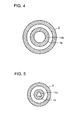
- Fig. 4 is a cross sectional view of a hydrodynamic gas bearing as a comparative example for Example 1.
- Fig. 5 is a cross sectional view representing a hydrodynamic gas bearing of the present invention in accordance with Example 2.
- Fig. 6 is a cross sectional view showing the shape of the outer periphery of the shaft body used in the conventional hydrodynamic gas bearing.
- Fig. 7 is a perspective view showing an exemplary shaft body having longitudinal grooves formed on the outer periphery, used in the conventional hydrodynamic gas bearing.
- Fig. 8 is a schematic cross section representing a conventional hydrodynamic gas bearing structure.
- Figs. 1A to 1C are cross sectional views showing, in an emphasized manner, one embodiment of the method of processing the outer peripheral surface of the shaft body in the hydrodynamic gas bearing in accordance with the present invention.
- shaft body 1 has a hollow portion 11 having an approximately regular triangle cross sectional shape as the hollow portion extending in the axial direction.
- Hollow portion 11 has a not-complete-round, line-symmetrical shape, symmetrical with respect to the line passing through the center of the cross section.
- the processing proceeds so that the cross sectional shape of the outer periphery of the shaft body comes to be complete-round with the cross sectional shape of the shaft body being deformed as shown in Fig. 1B.
- that portion of the outer periphery of the shaft body corresponding to the vertex of approximately regular triangle defining the cross sectional shape of follow portion 11 is much processed, and after processing, when the application of the pressure is released, the portion of the outer periphery of shaft body 1 corresponding to the protruded portion of the approximately regular triangle of hollow portion 11 has such a recessed shape as shown in Fig. 1C.
- the shaft body has a hollow portion extending in the axial direction and having not-completely-round symmetrical shape with respect to the line passing through the center of the cross section such as an approximately regular triangle, it is possible to provide such cross sectional shape of the outer periphery of the shaft body that can prevent the half speed whirl, by utilizing simple method of processing such as lathe.
- the out-of-roundness which represents deviation from complete round of the cross sectional shape of the outer periphery of the shaft body 1 can be appropriately controlled by adjusting process conditions such as the size of the hollow portion and the processing pressure.
- the processing method described above is similar to the conventional method except that the shaft body having a hollow portion of a line-symmetrical, not-complete-round shape is used. Therefore, processing of the shaft body which can prevent the half speed whirl phenomenon in accordance with the present invention does not cause any increase in manufacturing cost.
- Fig. 2 is a cross sectional view representing one embodiment of the hydrodynamic gas bearing in accordance with the present invention in which the shaft body has a hollow portion of which cross section is approximately regular triangle, and longitudinal grooves are formed at prescribed positions on the outer periphery of the shaft body.
- the outline representing the outer periphery of shaft body 1 is drawn considerably out of complete round in emphasized manner for easier understanding, in Fig. 2.
- shaft body 1 has a hollow portion 11.
- Hollow portion 11 has a cross sectional shape of approximately regular triangle.
- the first distance from the center O of the cross section of shaft body 1 to points b 0 , a 0 and d 0 on the outline corresponding to the inner periphery of hollow portion 11 changes along the peripheral direction of shaft body 1. More specifically, the first distance decreases from the length of Ob 0 to Oa 0 , and then increases to the length Od 0 .
- the first distance has the maximal value at the length Ob 0 or Od 0 , and hence a minimal value Oa 0 .
- the second distance from the center O of the cross section of shaft body 1 to points b, a and d on the outline corresponding to the outer periphery of shaft body 1 changes along the peripheral direction of shaft body 1. More specifically, the second distance increases from Ob to Oa and decreases to Od.
- the second distance has the minimal value Ob or Od and has a maximal value Oa, as it changes along the peripheral direction of shaft body 1.
- a cylindrical bearing body 2 is placed opposing to the outer peripheral surface of shaft body 1 with a space maintained in the radial direction. Assume that bearing body 2 rotates in the direction of the arrow R, as shown in Fig. 2. More specifically, by the rotation, air flow is caused in the same direction as represented by the arrow R in the space between shaft body 1 and bearing body 2.
- Longitudinal grooves 12 are formed on the outer peripheral surface of shaft body 1. Longitudinal grooves 12 are formed at positions represented by c on the outer periphery of shaft body 1.
- longitudinal groove 12 is formed as a recessed portion extending in the direction of the axial line at a portion c of the outer periphery of shaft body 1 in that range in which the first distance changes from the minimal value, that is, the length Oao to the maximal value, that is, the length OD 0 .
- the position on the outer periphery of shaft body 1 at which the longitudinal groove 12 is to be formed is determined with the shape of hollow portion 11 used as a reference, it becomes possible to suppress the half speed whirl phenomenon at the time of high speed rotation, and in addition, it becomes possible to control the position of forming the longitudinal grooves with respect to the outer shape of the outer periphery of the shaft body so as to suppress the floating rotational number low.
- the shape of the outer periphery of the shaft body and the positions of the longitudinal grooves can be controlled to attain both suppression of the half speed whirl phenomenon and lower floating rotational number.
- the shape of the outer periphery of the shaft body is controlled in accordance with the present invention, the half speed whirl phenomenon at the time of high speed rotation can be so effectively suppressed that the depth and width of the grooves contributing to lower floating rotational number can be made smaller. Therefore, degradation in stiffness of the shaft body resulting from the formation of grooves can be minimized.
- the hollow portion having approximately triangular cross sectional shape has been described above, similar functions and effects can be attained even when other polygonal shape than triangle, for example, approximately rectangular or approximately pentagonal shape is used.
- the hollow portion has one polygonal cross sectional shape in the above described embodiment, the hollow portion may have a curved shape such as an ellipse.
- one hollow portion is formed in the shaft body in the above described embodiment, a plurality of hollow portions may be formed to be line symmetrical with respect to the line passing through the center of the cross section of the shaft body to attain the similar functions and effects, provided that the hollow portions as a whole provide not-completely-round cross sectional shape.
- a plurality of hollow portions having approximately completely round cross sections may be formed arranged at equal space with respect to the center of the cross section of the shaft body.
- a method of processing using a lathe has been described as an example of the method of processing the outer periphery of the shaft body having the hollow portion.
- the outer periphery of the shaft body may be processed by a centerless grinder or the like.
- a material of a shaft body of stainless steel having an outer diameter of 16.0 mm, a hollow portion with a cross sectional shape of a square with each side being 9 mm (with the vertex chamfered with an arc of about 0.2 mm radius), and having a length of 50 mm was prepared.
- a portion of the shaft body material of a length of 40 mm was processed so that the outer periphery came to have the outer diameter of 15.0 mm.
- a bearing body (mass: 250g) of stainless steel having the length of 35 mm was combined with the shaft body sample 1-A obtained in this manner, with a space in the radial direction between the bearing body and the outer peripheral surface of the shaft body being 5 ⁇ m.
- Fig. 3 shows a cross sectional shape of the thus obtained hydrodynamic gas bearing.
- shaft body la has a hollow portion 11a.
- Bearing body 2 is placed opposing to shaft body la with a space therebetween.
- Exact outer peripheral shape such as out-of-roundness of shaft body la is not shown in Fig. 3.
- a material of a shaft body having a hollow portion of which cross section is circular with the diameter of 9 mm was processed in the similar manner as sample 1-A, and thus shaft body sample 1-B was prepared.
- the bearing body was combined with the shaft body in the similar manner as sample 1-A, and a hydrodynamic gas bearing was formed.
- Fig. 4 shows the cross sectional shape of the hydrodynamic gas bearing.
- shaft body 1b has a hollow portion 11b.
- Bearing body 2 is placed with a prescribed space from the outer peripheral surface from shaft body 1b.
- Fig. 4 does not show the exact shape of the outer peripheral surface and the out-of-roundness of shaft body 1b, either.
- Rotation test was performed on the hydrodynamic gas bearings structured as described above.
- the rotation test was performed by rotating bearing body 2 with respect to shaft bodies 1a and 1b, respectively.
- the bearing body 2 was floated with respect to shaft body 1a or 1b in the axial direction, by means of a permanent magnet.
- the floating rotational number and the ratio of occurrence of the half speed whirl phenomenon at the rotation number of 5000 rpm and 15000 rpm (among 10 samples) were studied.
- Outer diameter and out-of-roundness of shaft bodies 1a and 1b were measured for samples 1-A and 1-B. The results of measurement are as shown in Table 1.
- sample 1-B As a result of measurement of out-of-roundness, a pattern without any significant tendency was observed on sample 1-B, while the tendency that the portion of the outer periphery of the shaft body corresponding to the vertex of the square of the cross section of the hollow portion is recessed from complete roundness was apparent in sample 1-A.
- Table 1 when the shaft body sample 1-A having the hollow portion of which cross section is not-complete-round but square is used, the half speed whirl phenomenon at the time of high speed rotation can be suppressed as compared with when sample 1-B was used.
- a material of a shaft body of silicon nitride ceramics having an outer diameter of 8.4 mm, a hollow portion of which cross sectional shape is a regular triangle with its side being 4.5 mm (with the vertex chamfered with an arc of about 0. 2 mm radius) and a length of 30 mm was prepared.
- the shaft body material was processed so that the outer periphery thereof came to have the outer diameter of 8.0 mm, and thus a shaft body sample 2-A was fabricated.
- FIG. 5 shows the cross section of the hydrodynamic gas bearing structured in this manner.
- shaft body 1c has a hollow portion 11c.
- the bearing body 2 is placed opposing to the outer periphery of shaft body 1c.
- Fig. 5 does not show the exact shape of the outer peripheral surface and the out-of-roundness of shaft body 1c.
- a material of a solid shaft body not having the hollow portion was processed to fabricate a shaft body sample 2-B, which was combined with the similar bearing body as described above to form a hydrodynamic gas bearing.
- Rotation test was performed on the bearing bodies and the two shaft body samples 2-A and 2-B prepared in this manner.
- the bearing body was floated with respect to the shaft body in the axial direction by means of a permanent magnet, as in Example 1.
- Rotation test was performed by rotating the bearing body with respect to the shaft body.
- the shaft body sample 2-A had a tendency that the portion of the outer periphery of the shaft body which corresponds to the vertex of a regular triangle of the cross section of the hollow portion is recessed. The tendency was not so apparent with the difference between recess and protruded portions being small. It was found through analysis of the results of measurement of the surface shape by fast Fourier transform (FFT) that there were clearly three peaks in the peripheral direction corresponding to the vertexes of the regular triangle of the cross section of the hollow portion, in other words, the cross sectional shape of the outer periphery of the shaft body is approximately triangular with corners rounded.
- FFT fast Fourier transform
- a sample 2-AM was fabricated by forming a groove 12 at a position just in the middle between the points a and d on the outer periphery of shaft body 1 as shown in Fig. 2.
- the longitudinal groove was processed by a grinder on an outer peripheral surface of the shaft body sample parallel to the axial line, with the cutting depth of 5 ⁇ m. Further, similar processing was performed on the outer peripheral surface of the shaft body with the cutting depth of 5 ⁇ m, with the shaft body rotated by 4 ° at the central angle. In this manner, a shaft body having such a cross section as shown in Fig. 2 was obtained.
Landscapes
- Engineering & Computer Science (AREA)
- General Engineering & Computer Science (AREA)
- Mechanical Engineering (AREA)
- Physics & Mathematics (AREA)
- Fluid Mechanics (AREA)
- Sliding-Contact Bearings (AREA)
Applications Claiming Priority (2)
| Application Number | Priority Date | Filing Date | Title |
|---|---|---|---|
| JP10165368A JP2000002233A (ja) | 1998-06-12 | 1998-06-12 | 動圧気体軸受およびその製造方法 |
| JP16536898 | 1998-06-12 |
Publications (2)
| Publication Number | Publication Date |
|---|---|
| EP0964175A2 true EP0964175A2 (de) | 1999-12-15 |
| EP0964175A3 EP0964175A3 (de) | 2000-12-06 |
Family
ID=15811052
Family Applications (1)
| Application Number | Title | Priority Date | Filing Date |
|---|---|---|---|
| EP99304524A Withdrawn EP0964175A3 (de) | 1998-06-12 | 1999-06-11 | Hydrodynamisches Gaslager und Verfahren zur Herstellung eines solchen Lagers |
Country Status (3)
| Country | Link |
|---|---|
| US (2) | US6200033B1 (de) |
| EP (1) | EP0964175A3 (de) |
| JP (1) | JP2000002233A (de) |
Cited By (2)
| Publication number | Priority date | Publication date | Assignee | Title |
|---|---|---|---|---|
| WO2002012742A3 (en) * | 2000-08-07 | 2002-04-18 | Nippon Steel Corp | Hydrostatic gas bearing |
| EP1591678A4 (de) * | 2003-02-04 | 2008-08-20 | Nhk Spring Co Ltd | Welle für dynamisches lager, dynamisches lager und verfahren zur herstellung der welle |
Families Citing this family (3)
| Publication number | Priority date | Publication date | Assignee | Title |
|---|---|---|---|---|
| JP2000295816A (ja) * | 1999-04-02 | 2000-10-20 | Seiko Instruments Inc | モータ、モータの製造方法、及び回転体装置 |
| JP2002283174A (ja) * | 2001-03-26 | 2002-10-03 | Fanuc Ltd | 直線駆動装置 |
| US20130149155A1 (en) * | 2011-12-07 | 2013-06-13 | Asia Vital Components Co., Ltd. | Rotor shaft and cooling fan using same |
Citations (1)
| Publication number | Priority date | Publication date | Assignee | Title |
|---|---|---|---|---|
| JPH09264317A (ja) | 1996-03-28 | 1997-10-07 | Sumitomo Electric Ind Ltd | 動圧気体軸受構造 |
Family Cites Families (16)
| Publication number | Priority date | Publication date | Assignee | Title |
|---|---|---|---|---|
| JPS58163818A (ja) | 1982-03-19 | 1983-09-28 | Toshiba Corp | 動圧気体軸受装置 |
| JPS58224324A (ja) | 1982-06-24 | 1983-12-26 | Toshiba Corp | 回転鏡光偏向器 |
| JPS61201916A (ja) | 1985-03-06 | 1986-09-06 | Nippon Fueroo Furuideikusu Kk | 軸受装置 |
| JP2516967B2 (ja) * | 1987-04-30 | 1996-07-24 | 松下電器産業株式会社 | 軸受装置 |
| JPH01200320A (ja) | 1988-02-05 | 1989-08-11 | Hitachi Ltd | 回転鏡光偏向器 |
| JPH03204411A (ja) | 1989-08-24 | 1991-09-06 | Fuji Electric Co Ltd | 非対称溝付動圧空気軸受 |
| US5181783A (en) | 1990-07-16 | 1993-01-26 | Lincoln Laser Co. | Apparatus for eliminating whirl instability in a gas supported bearing |
| US5019738A (en) | 1990-07-16 | 1991-05-28 | Lincoln Laser Company | Self-pressurizing gas supported surface-roughness bearing |
| JPH05196031A (ja) | 1991-08-29 | 1993-08-06 | Lincoln Laser Co | 気体支持型の軸受の回転不安定性を除去する方法及び装置 |
| JP3456777B2 (ja) | 1993-12-24 | 2003-10-14 | 日本電産コパル電子株式会社 | 動圧空気軸受型光偏向器 |
| WO1996007832A1 (en) * | 1994-09-08 | 1996-03-14 | Kawasaki Jukogyo Kabushiki Kaisha | Reversing bearing device for double reversing propeller |
| JP3362593B2 (ja) | 1995-03-13 | 2003-01-07 | 住友電気工業株式会社 | 動圧気体軸受構造 |
| US5713670A (en) * | 1995-08-30 | 1998-02-03 | International Business Machines Corporation | Self pressurizing journal bearing assembly |
| DE69731353T2 (de) | 1996-04-30 | 2006-03-09 | Sumitomo Electric Industries, Ltd. | Lagervorrichtung und ein mit der Lagervorrichtung vorgesehener Spindelmotor |
| EP0918170B1 (de) * | 1997-02-28 | 2006-02-08 | Sumitomo Electric Industries, Ltd. | Dynamische gasdrucklagervorrichtung und diese verwendende abtastende optische ablenkvorrichtung |
| US5901013A (en) * | 1997-08-11 | 1999-05-04 | International Business Machines Corporation | Fluid spindle bearing vent |
-
1998
- 1998-06-12 JP JP10165368A patent/JP2000002233A/ja not_active Withdrawn
-
1999
- 1999-06-07 US US09/327,251 patent/US6200033B1/en not_active Expired - Fee Related
- 1999-06-11 EP EP99304524A patent/EP0964175A3/de not_active Withdrawn
-
2000
- 2000-05-22 US US09/575,876 patent/US6256885B1/en not_active Expired - Fee Related
Patent Citations (1)
| Publication number | Priority date | Publication date | Assignee | Title |
|---|---|---|---|---|
| JPH09264317A (ja) | 1996-03-28 | 1997-10-07 | Sumitomo Electric Ind Ltd | 動圧気体軸受構造 |
Cited By (2)
| Publication number | Priority date | Publication date | Assignee | Title |
|---|---|---|---|---|
| WO2002012742A3 (en) * | 2000-08-07 | 2002-04-18 | Nippon Steel Corp | Hydrostatic gas bearing |
| EP1591678A4 (de) * | 2003-02-04 | 2008-08-20 | Nhk Spring Co Ltd | Welle für dynamisches lager, dynamisches lager und verfahren zur herstellung der welle |
Also Published As
| Publication number | Publication date |
|---|---|
| JP2000002233A (ja) | 2000-01-07 |
| US6200033B1 (en) | 2001-03-13 |
| EP0964175A3 (de) | 2000-12-06 |
| US6256885B1 (en) | 2001-07-10 |
Similar Documents
| Publication | Publication Date | Title |
|---|---|---|
| EP0918170B1 (de) | Dynamische gasdrucklagervorrichtung und diese verwendende abtastende optische ablenkvorrichtung | |
| JPS5913369Y2 (ja) | 円筒ころ軸受 | |
| US5873657A (en) | Conic fluid bearing and head drum and spindle motor each including the same | |
| US20030002757A1 (en) | Dynamic bearing device and motor having the same | |
| KR100730424B1 (ko) | 동압 베어링용 축, 동압 베어링 및 이 축의 제조 방법 | |
| JP4451771B2 (ja) | スピンドルモータ | |
| KR100486698B1 (ko) | 베어링시스템및이를적용한스핀들모터조립체 | |
| EP0837257B1 (de) | Dynamische gasdrucklagervorrichtung, verfahren zur herstellung dieser vorrichtung und verfahren zu seiner verwendung | |
| US6200033B1 (en) | Hydrodynamic gas bearing and manufacturing method thereof | |
| EP1517057A2 (de) | Bauteil einer hydrodynamischen Lagervorrichtung sowie Herstellungsverfahren des Bauteils der hydrodynamischen Lagervorrichtung | |
| KR101152223B1 (ko) | 동압 베어링 장치 | |
| KR19980030392A (ko) | 유체베어링 장치 | |
| JP3646269B2 (ja) | 動圧軸受 | |
| JPH10113832A (ja) | 動圧流体軸受の製造方法 | |
| JPS6211204B2 (de) | ||
| JP2023529042A5 (de) | ||
| KR100261098B1 (ko) | 자기보상형 밸런서 | |
| JP2002323052A (ja) | ころ軸受およびその製造方法 | |
| JPH10341553A (ja) | 動圧スラスト軸受を備えたシャフトレス薄型モータ | |
| JP2003166524A (ja) | 動圧軸受装置 | |
| JP2003139137A (ja) | 動圧型軸受ユニットおよびその製造方法 | |
| JP2001140858A (ja) | 動圧流体軸受装置及びその製造装置 | |
| JPH03128649A (ja) | スピンドルモータ | |
| JPS61262221A (ja) | 動圧流体軸受装置 | |
| KR20010063011A (ko) | 스핀들 모터 |
Legal Events
| Date | Code | Title | Description |
|---|---|---|---|
| PUAI | Public reference made under article 153(3) epc to a published international application that has entered the european phase |
Free format text: ORIGINAL CODE: 0009012 |
|
| AK | Designated contracting states |
Kind code of ref document: A2 Designated state(s): DE FR GB IT |
|
| AX | Request for extension of the european patent |
Free format text: AL;LT;LV;MK;RO;SI |
|
| PUAL | Search report despatched |
Free format text: ORIGINAL CODE: 0009013 |
|
| AK | Designated contracting states |
Kind code of ref document: A3 Designated state(s): AT BE CH CY DE DK ES FI FR GB GR IE IT LI LU MC NL PT SE |
|
| AX | Request for extension of the european patent |
Free format text: AL;LT;LV;MK;RO;SI |
|
| 17P | Request for examination filed |
Effective date: 20001204 |
|
| AKX | Designation fees paid |
Free format text: DE FR GB IT |
|
| 17Q | First examination report despatched |
Effective date: 20040212 |
|
| GRAP | Despatch of communication of intention to grant a patent |
Free format text: ORIGINAL CODE: EPIDOSNIGR1 |
|
| RTI1 | Title (correction) |
Free format text: HYDRODYNAMIC GAS BEARING |
|
| STAA | Information on the status of an ep patent application or granted ep patent |
Free format text: STATUS: THE APPLICATION IS DEEMED TO BE WITHDRAWN |
|
| 18D | Application deemed to be withdrawn |
Effective date: 20050203 |