EP0963880B1 - Sicherheitsgurt mit aufblasbaren Kammern - Google Patents
Sicherheitsgurt mit aufblasbaren Kammern Download PDFInfo
- Publication number
- EP0963880B1 EP0963880B1 EP99111128A EP99111128A EP0963880B1 EP 0963880 B1 EP0963880 B1 EP 0963880B1 EP 99111128 A EP99111128 A EP 99111128A EP 99111128 A EP99111128 A EP 99111128A EP 0963880 B1 EP0963880 B1 EP 0963880B1
- Authority
- EP
- European Patent Office
- Prior art keywords
- chamber
- inflatable belt
- belt
- inflatable
- gas
- Prior art date
- Legal status (The legal status is an assumption and is not a legal conclusion. Google has not performed a legal analysis and makes no representation as to the accuracy of the status listed.)
- Expired - Lifetime
Links
Images


Classifications
-
- B—PERFORMING OPERATIONS; TRANSPORTING
- B60—VEHICLES IN GENERAL
- B60R—VEHICLES, VEHICLE FITTINGS, OR VEHICLE PARTS, NOT OTHERWISE PROVIDED FOR
- B60R21/00—Arrangements or fittings on vehicles for protecting or preventing injuries to occupants or pedestrians in case of accidents or other traffic risks
- B60R21/02—Occupant safety arrangements or fittings, e.g. crash pads
- B60R21/16—Inflatable occupant restraints or confinements designed to inflate upon impact or impending impact, e.g. air bags
- B60R21/18—Inflatable occupant restraints or confinements designed to inflate upon impact or impending impact, e.g. air bags the inflatable member formed as a belt or harness or combined with a belt or harness arrangement
-
- B—PERFORMING OPERATIONS; TRANSPORTING
- B60—VEHICLES IN GENERAL
- B60R—VEHICLES, VEHICLE FITTINGS, OR VEHICLE PARTS, NOT OTHERWISE PROVIDED FOR
- B60R21/00—Arrangements or fittings on vehicles for protecting or preventing injuries to occupants or pedestrians in case of accidents or other traffic risks
- B60R21/02—Occupant safety arrangements or fittings, e.g. crash pads
- B60R21/16—Inflatable occupant restraints or confinements designed to inflate upon impact or impending impact, e.g. air bags
- B60R21/23—Inflatable members
- B60R21/231—Inflatable members characterised by their shape, construction or spatial configuration
- B60R21/2334—Expansion control features
- B60R21/2342—Tear seams
-
- B—PERFORMING OPERATIONS; TRANSPORTING
- B60—VEHICLES IN GENERAL
- B60R—VEHICLES, VEHICLE FITTINGS, OR VEHICLE PARTS, NOT OTHERWISE PROVIDED FOR
- B60R21/00—Arrangements or fittings on vehicles for protecting or preventing injuries to occupants or pedestrians in case of accidents or other traffic risks
- B60R21/02—Occupant safety arrangements or fittings, e.g. crash pads
- B60R21/16—Inflatable occupant restraints or confinements designed to inflate upon impact or impending impact, e.g. air bags
- B60R21/23—Inflatable members
- B60R21/239—Inflatable members characterised by their venting means
Definitions
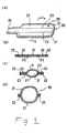
- the present invention relates to an inflatable belt and an inflatable belt device for protecting a vehicle occupant during a vehicle collision and, more particularly, to an inflatable belt which can be inflated with gas introduced from a gas inlet and an inflatable belt device having such an inflatable belt, according to the preamble of claim 1.
- This passenger protective device 1 includes a shoulder belt 2 extending diagonally from the right side to the left side of a passenger, a lap belt 3 extending from the right side to the left side of the passenger, a buckle 4 fixed to, for example, a vehicle floor, a tongue 5 to be inserted into and engaged with the buckle 4 when the passenger wears the belt, and an intermediate guide 6 for guiding the shoulder belt 2.
- the shoulder belt 2 includes a webbing 2a, which is the same as a typical conventional seat belt, and an inflatable belt 2b connected to an end of the webbing 2a.
- the webbing 2a is slidably hung in the intermediate guide 6.
- the other end of the webbing 2a is connected to a shoulder belt retractor 7 with an emergency locking mechanism (ELR), which is fixed to the vehicle body.
- ELR emergency locking mechanism
- the webbing 2a is arranged such that it is wound into the shoulder belt retractor 7.
- the inflatable belt 2b is positioned so that it contacts the passenger and is connected to the tongue 5 at an end opposite to the end connected to the webbing 2a.
- the lap belt 3 is composed of a webbing, which is the same as a typical conventional sear belt, having one end is connected to the tongue 5 and the other end connected to a lap belt retractor 8 (ELR), which is fixed to the vehicle body.
- a gas generator 9 is connected to the buckle 4. The gas generator 9 is actuated in emergency situations, e.g., vehicle collisions, to generate high-pressure gas.
- the tongue 5 and the buckle 4 are each provided with passages for introducing gas from the gas generator 9 into the inflatable belt 2b.
- the inflatable belt 2b of the shoulder belt 2 includes a belt body 2c formed in an envelope-like shape and a cover 2d.
- the belt body 2c is folded, shown in solid lines in Figure 3(b), and then covered by the cover 2d.
- the ends of the cover 2d are then connected to each other by stitching 2e so that the inflatable belt 2b is maintained in a band-like configuration.
- the stitching 2e of the cover 2d is easily torn by the force of the shoulder belt 2 expanding when the gas generator 9 is actuated so that the inflatable belt 2b is deployed, shown by a two-dot chain line in Figure 3(b).
- the belt body 2c is made of, for example, rubber coated fabric and the cover 2d is made of a flexible knit with excellent stretchability.
- Figures 4(a) through 4(d) are perspective views illustrating the manufacturing process of a conventional inflatable belt.
- two pieces of base fabrics 11, 12 are first cut to correspond to the configuration of a belt body being manufactured.
- the base fabrics 11, 12 are then superposed on each other ( Figure 4(a)) and sewn together along their peripheries to make an envelope-like or elongated belt body 14 ( Figure 4(b), numeral 13 designates stitching).
- the belt body 14 is longitudinally folded into a band-like configuration ( Figure 4 (c)).
- the belt body 14 is accommodated in a knit cover 15 ( Figure 4 (d)), thereby making the inflatable belt 16.
- the closest prior art document US-A-5,466,003 discloses an inflatable seat belt apparatus which is formed of an inflatable portion which is usually maintained in a band shape and has an envelope part inflated and deployed in a spindle shape by introducing gas generated by a gas generating device, the gas generating device acting in case of exceeding a predetermined threshold, a webbing having the inflatable portion extending over at least a range directly contacting with an occupant, a tongue fixed to an end of the inflatable portion and having a gas path from the gas generating device and a buckle to which the tongue is detachably engaged.
- the inflatable portion has an elastic inflatable unit inserted into the envelope part and is inflated and deployed by introducing the gas generated by the gas generating device into the elastic inflatable unit via a filter.
- the US-A-3,888,503 discloses an inflatable restraining band for vehicle safety systems having a series of sections, some of which are inflatable to a greater degree than others interconnecting them.
- the inside of the conventional inflatable belt is composed of only a single chamber.
- a gas inlet is provided only at one end side of the belt body, thus, the belt body is inflated from the one end side toward the other end side when gas is introduced from the gas generator.
- the gas generator must have a capacity that is large enough to generate a large amount of gas in short period of time.
- a preferred embodiment of the invention intended to accomplish at least some of the foregoing objects includes a gas inlet at one end of the inflatable belt; a first chamber communicating with the gas inlet; and a second chamber separated from the first chamber, wherein, when a gas pressure inside the first chamber reaches a predetermined value, the first chamber and the second chamber fluidly communicate with each other.
- a belt body 20 which is formed in an envelope or elongated configuration by superposing two long base fabrics 21, 21 on each other and then sewing them along their peripheries with a first sewing yarn 22.
- a gas inlet 24 is formed at one end side of the belt body 20.
- the inside of the belt body 20 is divided by second sewing yarns 23
- the gas inlet 24 is connected to, for example, a tongue having a gas duct.
- the tongue is engaged with a buckle having a gas duct and a gas generator, so as to allow gas from the gas generator to be introduced into the belt body 20 via the gas ducts.
- the second sewing yarns 23 divide the inside of the belt body 20 into a first chamber 31 and two second chambers 32.
- the first and the two second chambers extend in the longitudinal direction.
- the second sewing yarns 23 preferably are weaker than the first sewing yarn 22 so that the second sewing yarns 23 break when the gas pressure in the first chamber 31 reaches a predetermined value.
- the second chambers 32 extend along both sides of the first chamber 31.
- One of the second chambers 32 is provided with a vent hole 25.
- the belt body 20 is also folded into a long band-like configuration and is enclosed by a cover to make an inflatable belt as shown in Figures 3(a), 3(b).
- the first chamber 31 can be quickly inflated from the end nearer to the inlet 24 to the other end prior to the second chambers 32 being inflated. During this first inflation segment, gas is not discharged through the vent hole 25. Thus, the first chamber 31 is inflated sufficiently quickly even with a small output from the gas generator.
- the second chambers 32 are inflated. During inflation of the second chambers, gas is introduced quickly throughout the second chambers 32 from the already inflated first chamber 31, so that the entire inflatable belt 30 can be inflated in a short period of time.
- a belt body 20A which is made from two long fabrics 21, 21 superposed on each other and then sewn together along their peripheries with a first sewing yarn 22.
- the belt body 20A has a gas inlet 24 at one end side thereof.
- the inside of the belt body 20A is divided into a first chamber 41, a second chamber 42, and a third chamber 43 by second and third sewing yarns 26, 27, which extend in the width direction of the belt body 20A.
- the second and third sewing yarns 26, 27 are weaker than the first sewing yarn 22 so that the second and third sewing yarns 26, 27 are broken when the gas pressure in the first chamber 41 or the second chamber 42 reaches a predetermined value.
- the first chamber 41 communicates directly with the gas inlet 24 formed on one end side of the belt body 20A.
- the first chamber 41 extends from one end side to approximately the middle of the belt body 20A.
- the third chamber 43 is positioned at the other end side of the belt body 20A and the second chamber 42 is positioned between the first chamber 41 and the third chamber 43.
- the third chamber 43 has a vent bole 25 formed therein
- the third sewing yarn 27 is broken so that the third chamber 43 is also inflated.
- gas in the first and second chambers 41, 42 is not discharged through the vent hole 25 until the third sewing yarn 27 is broken and the third chamber 43 of the belt body 20A is inflated. Therefore, the portion from the one end side (the gas inlet 24 side) to approximately the middle of the inflatable belt can be quickly inflated without increasing the output of the gas generator. Because the occupant's weight is mostly rested on the vicinity of the middle of the belt body 20A during a vehicle collision, the quick inflation of the vicinity of the middle of the inflatable belt enables sufficient protection of the occupant even before the third chamber 43 is fully inflated.
- the second and third yarns may or may not have identical strengths.
- Stitching or sewing yarns 23, 26, 27 are used to construct the first chambers 31, 41, the second chambers 32, 42, and the third chamber 43. It is possible, however, to use an adhesive agent in place of the stitching or sewing yarn.
- a thermoplastic resin may be applied to the base fabrics and the chambers defined by welding or melting the resin between the base fabrics.
- the inflatable belt can be sufficiently quickly inflated without increasing the volume generated by the gas generator and without increasing the gas generation speed.
- An inflatable belt of the present invention is a belt for protecting an occupant in a vehicle seat which is inflated when gas is introduced into the inflatable belt through a gas inlet.
- the inside of the inflatable belt is divided into at least two chambers in which a first chamber communicates with the gas inlet.
- the at least one second chamber is separated from the first chamber by a partition. The partition allows the first chamber to communicate with the second chamber when the gas pressure in the first chamber reaches a predetermined value.
- An inflatable belt device or safety belt restraint system of the present invention includes such an inflatable belt and a gas generator for inflating the inflatable belt.
- the gas generator when the gas generator is actuated to introduce gas into the inflatable belt, the first chamber is quickly inflated and, after that, the partition is opened so that the second chamber is inflated.
- the first chamber is designed to extend from one end side to the other end side of the inflatable belt, so that the inflatable belt can be quickly inflated from the one end side to the other end side by inflating the first chamber.
- the first chamber is inflated with the gas being kept in high pressure because the volume of the first chamber is smaller than that of the whole inflatable belt.
- the partition is opened so that the gas enters into the second chamber.
- gas is introduced quickly throughout the second chambers from the already inflated first chamber, so that the entire inflatable belt is inflated in a short period of time.
- the first chamber is designed to extend from one end side to the vicinity of the middle of the inflatable belt, and the second chamber is disposed on the other end side.
- the portion from the one end side to the vicinity of the middle of the inflatable belt is first quickly inflated and, after that, the second chamber on the other end side is inflated.
- the vicinity of the middle of the inflatable belt, where the occupant's weight is mostly rested on, can be sufficiently inflated in a short period of time.
- the partition is preferably constructed from stitching by yarn, adhesion, welding, or melting.
- the second chamber or the third chamber communicate with the atmosphere through a vent hole.
- gas from the gas generator is not discharged through the vent hole when the first chamber is being inflated, so that the first chamber can be quickly inflated.
Landscapes
- Engineering & Computer Science (AREA)
- Mechanical Engineering (AREA)
- Air Bags (AREA)
Claims (16)
- Aufblasbarer Gurt zum Schützen eines Insassen in einem Fahrzeugsitz, wobei der aufblasbare Gurt umfasst:dadurch gekennzeichnet, dasseinen Gaseinlass (24) an einem Ende des aufblasbaren Gurtes;eine erste Kammer (31, 41), die in Verbindung mit dem Gaseinlass (24) steht; undeine zweite Kammer (32, 42), die von der ersten Kammer (31, 41) getrennt ist, die erste Kammer (31, 41) und die zweite Kammer (32, 42) strömungstechnisch miteinander verbunden sind, wenn ein Gasdruck im Inneren der ersten Kammer (31, 41) einen vorgegebenen Wert erreicht,
ein Haftmittel die erste Kammer (31, 41) von der zweiten Kammer (32, 42) trennt und das Haftmittel aufreißt, wenn der Gasdruck den vorgegebenen Wert erreicht hat. - Aufblasbarer Gurt nach Anspruch 1, wobei sich die ersten und die zweiten Kammern (31, 41; 32, 42) in eine Längsrichtung von dem Gaseinlass (24) bis zu einem anderen Ende des aufblasbaren Gurtes erstrecken.
- Aufblasbarer Gurt nach Anspruch 1, wobei sich die ersten und zweiten Kammern (31, 41; 32, 42) sich senkrecht zu einer Längsrichtung des aufblasbaren Gurtes erstrecken.
- Aufblasbarer Gurt nach Anspruch 1, wobei sich die erste Kammer (31, 41) von dem Gaseinlass (24) bis ungefähr zur Mitte des aufblasbaren Gurtes erstreckt.
- Aufblasbarer Gurt nach Anspruch 3, der weiterhin eine dritte Kammer (43) aufweist, die zwischen der zweiten Kammer (42) und dem anderen Ende des aufblasbaren Gurtes angeordnet ist.
- Aufblasbarer Gurt nach einem der Ansprüche 1 bis 5, der weiterhin ein Lüftungsloch (25) in der zweiten Kammer (32, 42) aufweist.
- Aufblasbarer Gurt nach Anspruch 5, der weiterhin ein Lüftungsloch (25) in der dritten Kammer (43) aufweist.
- Aufblasbarer Gurt, der umfasst:dadurch gekennzeichnet, dasszwei Basisgewebestreifen (11, 12), die an ihren Umfängen miteinander verbunden sind und einen Gaseinlass (24) an einem Ende aufweisen;eine erste und eine zweite Kammer (31, 32; 41, 42), wobei die erste Kammer (31, 41) direkt mit dem Gaseinlass (24) verbunden ist, und wenn ein Druck in der ersten Kammer (31, 41) einen vorgegebenen Wert erreicht hat, die erste Trennwand aufreißt und die erste Kammer (31, 41) und die zweite Kammer (32, 42) strömungstechnisch miteinander verbunden sind,
eine erste Abtrennung, die durch ein Zusammenhaften der Basisgewebestreifen (11, 12) gebildet ist, die verbundenen Basisgewebestreifen (11, 12) in eine erste und zweite Kammer (31, 32; 41, 42) trennt. - Aufblasbarer Gurt nach Anspruch 8, der weiterhin eine zweite Abtrennung aufweist, die die verbundenen Basisgewebestreifen (11, 12) in die erste Kammer (31, 41) und zwei zweite Kammern (32, 42) aufteilt, die sich in eine Längsrichtung ausdehnen, wobei, wenn die erste Kammer (31, 41) einen vorgegebenen Druck erreicht, die erste Kammer (31, 41) und die zwei zweiten Kammern (31, 41; 32, 42) strömungstechnik miteinander verbunden sind.
- Aufblasbarer Gurt nach Anspruch 8, wobei die ersten und zweiten Kammern (31, 41; 32, 42) sich in eine Längsrichtung ausdehnen.
- Aufblasbarer Gurt nach Anspruch 8, wobei die erste und zweiten Kammern (31, 41; 32, 42) sich in eine Richtung erstrecken, die senkrecht zu einer Längsrichtung verläuft.
- Aufblasbarer Gurt nach Anspruch 8, der weiterhin eine zweite Abtrennung umfasst, die die verbundenen Basisgewebestreifen (11, 12) in die erste, die zweite und eine dritte Kammer (31, 41; 32, 42; 43) trennt, die sich in eine Richtung erstrecken, die senkrecht zu einer Längsrichtung verläuft, wobei, wenn die erste Kammer (31, 41) einen vorgegebenen Druck erreicht, die erste Abtrennung aufreißt und die ersten und zweiten Kammern (31, 41; 32, 42) strömungstechnisch miteinander verbunden sind und wobei, wenn die zweite Kammer (32, 42) einen vorgegebenen Druck erreicht, die zweite Abtrennung aufreißt und die zweiten und dritten Kammern (32, 42; 43) strömungstechnisch miteinander verbunden sind.
- Aufblasbarer Gurt nach Anspruch 8, wobei die erste Abtrennung durch Zusammennähen der zwei Basisgewebestreifen (11, 12) ausgebildet ist.
- Aufblasbarer Gurt nach Anspruch 8, wobei die Basisgewebestreifen (11, 12) mit einem Harz beschichtet sind.
- Aufblasbarer Gurt nach Anspruch 14, wobei die erste Abtrennung durch Verschmelzen der zwei Basisgewebestreifen (11, 12) gebildet wird.
- Ein Sicherheitsgurt, der umfasst:einen Gurt;einen aufblasbaren Gurt, der an einem Ende mit dem Gurt verbunden ist, wobei der aufblasbare Gurt einen Gurtkörper (20) und einen Gaseinlass (24) an einem Ende des aufblasbaren Gurtes aufweist;eine erste Kammer (31, 41), die mit dem Gaseinlass (24) verbunden ist; und eine zweite Kammer (32, 42), die von der ersten Kammer (31, 41) getrennt ist; wenn ein Gasdruck innerhalb der ersten Kammer (31, 41) einen vorgegebenen Wert erreicht, stehen die erste Kammer (31, 41) und die zweite Kammer (32, 42) strömungstechnisch miteinander in Verbindung;eine Zunge mit einer Leitung, die mit dem Gaseinlass (24) des aufblasbaren Gurtes verbunden ist; undeinen Gasgenerator, der mit der Leitung der Zunge zum Zuführen von Gas in den aufblasbaren Gurt verbunden ist, um den aufblasbaren Gurt aufzublasen, dadurch gekennzeichnet, dass die zweite Kammer (32, 42) von der ersten Kammer (31, 41) durch eine Abtrennung, die durch das Verbinden des aufblasbaren Gurtkörpers (20) miteinander mittels Nähen oder Kleben erhalten wird, getrennt ist, wobei die Abtrennung ausgebildet ist, um die zweite Kammer (32, 42) nach dem Aufblasen der ersten Kammer (31, 41) aufzublasen.
Applications Claiming Priority (2)
| Application Number | Priority Date | Filing Date | Title |
|---|---|---|---|
| JP15929798 | 1998-06-08 | ||
| JP10159297A JPH11348721A (ja) | 1998-06-08 | 1998-06-08 | エアベルト及びエアベルト装置 |
Publications (2)
| Publication Number | Publication Date |
|---|---|
| EP0963880A1 EP0963880A1 (de) | 1999-12-15 |
| EP0963880B1 true EP0963880B1 (de) | 2003-08-06 |
Family
ID=15690726
Family Applications (1)
| Application Number | Title | Priority Date | Filing Date |
|---|---|---|---|
| EP99111128A Expired - Lifetime EP0963880B1 (de) | 1998-06-08 | 1999-06-08 | Sicherheitsgurt mit aufblasbaren Kammern |
Country Status (4)
| Country | Link |
|---|---|
| US (1) | US6276714B1 (de) |
| EP (1) | EP0963880B1 (de) |
| JP (1) | JPH11348721A (de) |
| DE (1) | DE69910124T2 (de) |
Families Citing this family (21)
| Publication number | Priority date | Publication date | Assignee | Title |
|---|---|---|---|---|
| JPH11348721A (ja) * | 1998-06-08 | 1999-12-21 | Takata Kk | エアベルト及びエアベルト装置 |
| JP3888009B2 (ja) * | 1999-10-28 | 2007-02-28 | タカタ株式会社 | エアベルト及びエアベルト装置 |
| WO2001068414A1 (en) * | 2000-03-13 | 2001-09-20 | Am-Safe Incorporated | Air bag with pressure release and having hollow compartments within the bag |
| JP4573285B2 (ja) * | 2000-12-18 | 2010-11-04 | タカタ株式会社 | インフレータブルシートベルト装置 |
| US6619752B1 (en) | 2001-11-21 | 2003-09-16 | Cosco Management, Inc. | Extensible tether for juvenile vehicle seat |
| US6550805B1 (en) * | 2002-02-01 | 2003-04-22 | Ford Global Technologies, Llc | Occupant restraint belt with inflatable presenter |
| JP3912195B2 (ja) * | 2002-06-12 | 2007-05-09 | タカタ株式会社 | 乗員保護装置 |
| EP1638819B1 (de) * | 2003-04-10 | 2007-12-05 | Autoliv Development Ab | Airbag und verfahren zur montage eines airbags |
| GB2410010B (en) * | 2004-01-19 | 2007-01-31 | Autoliv Dev | Improvements in or relating to an air-bag arrangement |
| JP5446657B2 (ja) * | 2009-09-18 | 2014-03-19 | タカタ株式会社 | エアベルト及びエアベルト装置 |
| US8469397B2 (en) * | 2011-04-13 | 2013-06-25 | Amsafe, Inc. | Stitch patterns for restraint-mounted airbags and associated systems and methods |
| US8439398B2 (en) | 2011-07-29 | 2013-05-14 | Amsafe, Inc. | Inflator connectors for inflatable personal restraints and associated systems and methods |
| US8523220B1 (en) | 2012-03-19 | 2013-09-03 | Amsafe, Inc. | Structure mounted airbag assemblies and associated systems and methods |
| US9511866B2 (en) | 2012-03-19 | 2016-12-06 | Amsafe, Inc. | Structure mounted airbag assemblies and associated systems and methods |
| JP6300521B2 (ja) * | 2013-12-27 | 2018-03-28 | タカタ株式会社 | エアベルト及びエアベルト装置 |
| US9221415B2 (en) | 2014-02-19 | 2015-12-29 | Ford Global Technologies, Llc | Method of assembling and packing an automotive airbag |
| US9352839B2 (en) | 2014-10-02 | 2016-05-31 | Amsafe, Inc. | Active positioning airbag assembly and associated systems and methods |
| US9944245B2 (en) | 2015-03-28 | 2018-04-17 | Amsafe, Inc. | Extending pass-through airbag occupant restraint systems, and associated systems and methods |
| EP3283336B1 (de) | 2015-04-11 | 2019-11-20 | AmSafe, Inc. | Aktives entlüftungssystem für airbag |
| US10604259B2 (en) | 2016-01-20 | 2020-03-31 | Amsafe, Inc. | Occupant restraint systems having extending restraints, and associated systems and methods |
| GB2579668B (en) * | 2018-12-12 | 2021-01-13 | Ford Global Tech Llc | An airbag |
Family Cites Families (20)
| Publication number | Priority date | Publication date | Assignee | Title |
|---|---|---|---|---|
| US3146460A (en) * | 1962-09-14 | 1964-09-01 | Barnabas D Henderson | Segment safety device |
| US3430979A (en) * | 1966-11-17 | 1969-03-04 | Chrysler Corp | Inflatable cushioning device |
| DE2046426A1 (de) * | 1970-09-21 | 1972-03-23 | Biesterfeldt, Harald, 2081 Hemendingen | Sicherheitsvorrichtung für in Landoder Luftfahrzeugen befindliche Personen |
| CA954161A (en) * | 1970-10-23 | 1974-09-03 | John J. Sack | Energy absorbtion |
| US3801156A (en) * | 1971-11-15 | 1974-04-02 | H Granig | Safety-belt |
| DE2358070A1 (de) * | 1972-11-27 | 1974-06-06 | Nissan Motor | Sicherheitsgurt |
| DE2260366A1 (de) * | 1972-12-09 | 1974-07-04 | Braun Ag | Sicherheitseinrichtung fuer kraftfahrzeuge, insbesondere zum schutz von kindern und jugendlichen |
| US3830519A (en) * | 1973-01-10 | 1974-08-20 | Allied Chem | Fiber reinforced inflatable restraining band for vehicles |
| US3888503A (en) * | 1973-02-22 | 1975-06-10 | Allied Chem | Limiting of continuous extent of inflatable restraint |
| DE3232946A1 (de) * | 1982-09-04 | 1984-03-08 | Wolfgang 5000 Köln Schmalz | Sicherheitsgurt, insbesondere mit automatischer aufrollvorrichtung, mit einem den auflagedruck mindernden polsterteil |
| JP3057112B2 (ja) | 1991-09-24 | 2000-06-26 | タカタ株式会社 | インフレータブルシートベルト装置 |
| US5466003A (en) | 1994-06-30 | 1995-11-14 | Takata Corporation | Inflatable seat belt having bag filter |
| US5456491A (en) * | 1994-08-16 | 1995-10-10 | Chen; Fou-Min | Air bag received in a safety belt |
| ATE176637T1 (de) * | 1995-09-29 | 1999-02-15 | Salvatore Russo | Sicherheitsgurt, kombiniert mit luftsäcken |
| DE29605897U1 (de) * | 1996-03-29 | 1996-07-25 | Trw Repa Gmbh | Gassack |
| US5833265A (en) * | 1997-02-21 | 1998-11-10 | Takata, Inc. | Airbag with excursion restrictors |
| JPH10258239A (ja) * | 1997-03-19 | 1998-09-29 | Ebara Corp | 切削型破砕機 |
| JP3741850B2 (ja) * | 1997-12-25 | 2006-02-01 | 本田技研工業株式会社 | 乗員拘束装置 |
| JPH11342827A (ja) * | 1998-06-04 | 1999-12-14 | Honda Motor Co Ltd | エアベルト装置 |
| JPH11348721A (ja) * | 1998-06-08 | 1999-12-21 | Takata Kk | エアベルト及びエアベルト装置 |
-
1998
- 1998-06-08 JP JP10159297A patent/JPH11348721A/ja active Pending
-
1999
- 1999-06-08 US US09/327,546 patent/US6276714B1/en not_active Expired - Fee Related
- 1999-06-08 DE DE69910124T patent/DE69910124T2/de not_active Expired - Fee Related
- 1999-06-08 EP EP99111128A patent/EP0963880B1/de not_active Expired - Lifetime
Also Published As
| Publication number | Publication date |
|---|---|
| US6276714B1 (en) | 2001-08-21 |
| JPH11348721A (ja) | 1999-12-21 |
| DE69910124T2 (de) | 2004-06-09 |
| EP0963880A1 (de) | 1999-12-15 |
| DE69910124D1 (de) | 2003-09-11 |
Similar Documents
| Publication | Publication Date | Title |
|---|---|---|
| EP0963880B1 (de) | Sicherheitsgurt mit aufblasbaren Kammern | |
| US6419263B1 (en) | Seatbelt system having seamless inflatable member | |
| EP0928260B1 (de) | Sicherheitsgurtsystem mit einem nahtlosen aufblasbarem element | |
| US7293828B2 (en) | Child seat with deployable side airbags | |
| EP1087878B1 (de) | Gurtsystem mit aufblasbarem abschnitt innerhalb eines aussenabschnittes eines gurtes sowie verfahren zur insassensicherung | |
| US5797620A (en) | Knee guard device | |
| EP1738971B1 (de) | Insassenrückhaltevorrichtung | |
| US7954845B2 (en) | Knee-protecting airbag device | |
| US6419264B1 (en) | Air-belt device and method | |
| KR950023558A (ko) | 차량용 에어안전밸트 | |
| JP3741850B2 (ja) | 乗員拘束装置 | |
| EP0963883B1 (de) | Aufblasbarer Sicherheitsgurt für Kraftfahrzeuge | |
| JP3340597B2 (ja) | 自動車用子供安全シート | |
| US6409212B1 (en) | Belt system for restraining a vehicle occupant | |
| CN217435673U (zh) | 安全气囊装置和组件 | |
| WO1998012077A1 (en) | Apparatus for protecting a vehicle occupant | |
| EP0965496B1 (de) | Kombination eines aufblasbaren Gurtes und einer Schlosszunge und Kombination des aufblasbaren Gurtes mit einem gewebten Gurtband | |
| JPH10226295A (ja) | ガス圧膨張式シートベルト | |
| EP0830991A1 (de) | Schutzvorrichtung für Fahrzeuginsassen | |
| JP2000025546A (ja) | シートベルト装置 | |
| EP0970855B1 (de) | Aufblasbare Sicherheitsgurtvorrichtung mit seiner Steckzunge | |
| EP0963881A1 (de) | Aufblasbarer Sicherheitsgurt | |
| KR100725337B1 (ko) | 차량용 시트벨트 이중 에어백 장치 | |
| KR20190108688A (ko) | 시트벨트용 에어백장치 | |
| JP2001001857A (ja) | 頭部保護エアバッグ装置 |
Legal Events
| Date | Code | Title | Description |
|---|---|---|---|
| PUAI | Public reference made under article 153(3) epc to a published international application that has entered the european phase |
Free format text: ORIGINAL CODE: 0009012 |
|
| AK | Designated contracting states |
Kind code of ref document: A1 Designated state(s): DE GB |
|
| AX | Request for extension of the european patent |
Free format text: AL;LT;LV;MK;RO;SI |
|
| 17P | Request for examination filed |
Effective date: 20000429 |
|
| AKX | Designation fees paid |
Free format text: DE GB |
|
| 17Q | First examination report despatched |
Effective date: 20020320 |
|
| GRAH | Despatch of communication of intention to grant a patent |
Free format text: ORIGINAL CODE: EPIDOS IGRA |
|
| GRAH | Despatch of communication of intention to grant a patent |
Free format text: ORIGINAL CODE: EPIDOS IGRA |
|
| GRAA | (expected) grant |
Free format text: ORIGINAL CODE: 0009210 |
|
| AK | Designated contracting states |
Designated state(s): DE GB |
|
| REG | Reference to a national code |
Ref country code: GB Ref legal event code: FG4D |
|
| REF | Corresponds to: |
Ref document number: 69910124 Country of ref document: DE Date of ref document: 20030911 Kind code of ref document: P |
|
| PLBE | No opposition filed within time limit |
Free format text: ORIGINAL CODE: 0009261 |
|
| STAA | Information on the status of an ep patent application or granted ep patent |
Free format text: STATUS: NO OPPOSITION FILED WITHIN TIME LIMIT |
|
| 26N | No opposition filed |
Effective date: 20040507 |
|
| PGFP | Annual fee paid to national office [announced via postgrant information from national office to epo] |
Ref country code: DE Payment date: 20080612 Year of fee payment: 10 |
|
| PGFP | Annual fee paid to national office [announced via postgrant information from national office to epo] |
Ref country code: GB Payment date: 20080611 Year of fee payment: 10 |
|
| GBPC | Gb: european patent ceased through non-payment of renewal fee |
Effective date: 20090608 |
|
| PG25 | Lapsed in a contracting state [announced via postgrant information from national office to epo] |
Ref country code: GB Free format text: LAPSE BECAUSE OF NON-PAYMENT OF DUE FEES Effective date: 20090608 |
|
| PG25 | Lapsed in a contracting state [announced via postgrant information from national office to epo] |
Ref country code: DE Free format text: LAPSE BECAUSE OF NON-PAYMENT OF DUE FEES Effective date: 20100101 |