EP0963684B1 - Verfahren zur beeinflussung der stereo-kanaltrennung eines audiosignals und anordnung dazu - Google Patents
Verfahren zur beeinflussung der stereo-kanaltrennung eines audiosignals und anordnung dazu Download PDFInfo
- Publication number
- EP0963684B1 EP0963684B1 EP98906842A EP98906842A EP0963684B1 EP 0963684 B1 EP0963684 B1 EP 0963684B1 EP 98906842 A EP98906842 A EP 98906842A EP 98906842 A EP98906842 A EP 98906842A EP 0963684 B1 EP0963684 B1 EP 0963684B1
- Authority
- EP
- European Patent Office
- Prior art keywords
- signal
- auxiliary
- interference
- reception
- strength
- Prior art date
- Legal status (The legal status is an assumption and is not a legal conclusion. Google has not performed a legal analysis and makes no representation as to the accuracy of the status listed.)
- Expired - Lifetime
Links
- 238000000926 separation method Methods 0.000 title claims description 35
- 238000000034 method Methods 0.000 title claims description 12
- 230000005236 sound signal Effects 0.000 title claims description 11
- 238000011156 evaluation Methods 0.000 claims description 21
- 230000005540 biological transmission Effects 0.000 claims description 15
- 230000008859 change Effects 0.000 claims description 5
- 238000005457 optimization Methods 0.000 claims description 3
- 230000000630 rising effect Effects 0.000 claims 3
- 241001484259 Lacuna Species 0.000 claims 1
- 238000012360 testing method Methods 0.000 description 9
- 230000008901 benefit Effects 0.000 description 4
- 241000881711 Acipenser sturio Species 0.000 description 3
- 230000015572 biosynthetic process Effects 0.000 description 2
- 230000007423 decrease Effects 0.000 description 2
- 230000001419 dependent effect Effects 0.000 description 2
- 230000000694 effects Effects 0.000 description 2
- 238000001914 filtration Methods 0.000 description 2
- 238000012545 processing Methods 0.000 description 2
- 230000007704 transition Effects 0.000 description 2
- 230000009286 beneficial effect Effects 0.000 description 1
- 238000010586 diagram Methods 0.000 description 1
- 230000009467 reduction Effects 0.000 description 1
- 238000005070 sampling Methods 0.000 description 1
- 238000012549 training Methods 0.000 description 1
Images

Classifications
-
- H—ELECTRICITY
- H04—ELECTRIC COMMUNICATION TECHNIQUE
- H04S—STEREOPHONIC SYSTEMS
- H04S1/00—Two-channel systems
- H04S1/007—Two-channel systems in which the audio signals are in digital form
Definitions
- the invention relates to a method for influencing the Stereo channel separation of an audio signal to be played back and a radio receiver to carry out the inventive method according to the genus of independent claims.
- Modern radio transmitters emit radio signals whose Signal format the transmission of stereophonic audio signals enables and on the receiver side the surround sound stereophonic playback can be clearly heard.
- Radio receivers especially car radios, with a switching for a long time or smooth transition from stereophonic to monophonic Playback equipped by the reception field strength of a received broadcast signal. In such Radio receivers will drop when the reception field strength the channel separation is automatically reduced.
- EP 0 617 519 A2 describes a circuit arrangement for known such a radio receiver, in which from the Receiving field strength of a received broadcast signal on the Received field strength signal is derived in which continues to come from the received broadcast signal Interference signal indicating reception interference is derived, and in which the signal indicating the reception field strength and the interference signal multiplicative to form a Influencing the stereo channel separation of a audio signal to be reproduced using a stereo decoder supplied factor can be linked.
- radio receivers are able to Evaluation of by means of the radio data system (RDS) transmitted information known for the purpose of Optimization of the reception quality of a received Broadcast program briefly from a currently set one Transmission frequency to an alternative transmission frequency over which the same program is broadcast, be tuned being on the alternative during the stay Transmission frequency determines their reception quality and then the receiver on the transmission frequency with the best reception conditions is set.
- the alternative transmission frequency is used, for example the AF- (alternative Frequencies) data taken.
- Tuning the radio receiver to an alternative Transmitting frequency causes sudden and therefore disturbing changes in the Stereo channel separation of a reproduced audio signal.
- the inventive method and the inventive Broadcast receiver with the characteristics of independent Claims have the advantage that with strongly fluctuating Reception conditions or frequently occurring Reception interference, such as B. multipath, fast and frequent changes between stereophonic and monophonic Playback and the associated negative auditory impression in favor of a partially or completely monophonic Playback can be suppressed.
- the frequency of interference signal to be realized by means of a counter which if a fault occurs and if there is no Disturbance is decremented because of that counter required clock in a simple manner, for example from the System clock z. B. from the bit clock of the digital involved Signals can be derived.
- Radio receivers for receiving radio data signals automatic to optimize reception quality
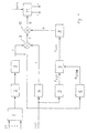
- FIG. 1 shows a block diagram of the part of an invention essential to the invention Broadcast receiver
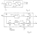
- Figure 2 shows an example of a Realization of the second evaluation circuit 6
- Figure 3 a Realization possibility for the stereo decoder 11
- FIG. 4 an example of a first in the first Evaluation circuit 4 realized characteristic
- Figure 5 a second realized in the third evaluation circuit Characteristic curve
- Figure 6 shows an example of that in the second Evaluation circuit 6 realized monotonically falling characteristic 62.
- FIG. 1 An embodiment of the part essential to the invention of a radio receiver according to the invention for implementation of the method according to the invention is shown in FIG. 1.
- stereo multiplesx signal MPX is supplied, audio signals for a left and a right channel (l, r) removable.
- the stereo multiplex signal MPX is processed in two signal paths, by low-pass filtering 113 of the stereo multiplex signal from this the sum signal (L + R) is isolated.
- one second signal path is by in-phase multiplication 111 with one from, for example, one in the stereo multiplex signal contained 19kHz pilot tone obtained 38kHz subcarrier and then eliminating undesirable Mixed products using a low pass 112 Difference signal (L - R), which is the difference of the signals for contains the left and right audio channels.
- the Generation is the subject of the following considerations any stereo channel separation between purely monophonic and Set purely stereophonic playback.
- Weighting circuit included inventive arrangement 1 are different reception disorders like Fluctuations in field strength, multi-path reception and interference noise indicating interference signals (ST) supplied, which are dependent the ranges of values they occupy and theirs desired influence on the stereo channel separation of a audio signal to be reproduced individually weighted and Formation of a common interference signal linked together, be added up in the present case.
- ST interference noise indicating interference signals
- the common interference signal is a threshold value decision 2 supplied by it with a predetermined threshold is evaluated so that the outcome of the Threshold decision 2 when the specified one is exceeded Threshold value due to the common interference signal from one first changes to a second state.
- Threshold value due to the common interference signal from one first changes to a second state.
- the case is for the first and the second state Values 1 and 0 selected.
- the output of the threshold decision 2 is one Edge control 3 for controlling the slope of the supplied signal supplied.
- This is done in such a way that their output signal, hereinafter referred to as the first interference auxiliary signal s denotes when the output of the Threshold decision maker two from the first to the second Condition suddenly takes on a fourth value and as soon as the output of the threshold decision 2 at first Value decreases after a predetermined time function z. B. to the third value within a few 10 ms goes back.
- the predefined time function is in the present Case realized in the form of a linear course, it can but it can also be provided that the first auxiliary auxiliary signal s after a non-linear, for example exponential Course to the third value and thus towards stereophonic playback returns.
- a first evaluation circuit 4 to form a first field strength auxiliary signal x, which is the reception field strength of the received radio signal identifies, supplied.
- the Field strength signal FST is in the present case by Rectification and low pass filtering of the Intermediate frequency signal that by mixing down the Received signal is obtained in the intermediate frequency level, generated.
- Field strength signal FST with a monotonically increasing in In the present case, the linear characteristic is evaluated so that for higher reception field strengths, higher values for the first Field strength auxiliary signal x result.
- the characteristic curve has a saturation range, so that for very high reception field strengths, no changes to the first field strength auxiliary signal x.
- the range of values the first field strength auxiliary signal lies in present case between the values 0 for a very low reception field strength FST and 1 for high and highest Reception field strengths.
- An example of one in the first Evaluation circuit 4 realized non-linear characteristic is shown in Figure 4.
- a third signal path 5 to 8 comprises a second evaluation circuit 6 for forming a signal which characterizes the frequency of reception disturbances, ie the number of disturbances per unit of time, hereinafter referred to as second disturbance auxiliary signal P disturbance , to which the first disturbance auxiliary signal s is supplied.
- FIG. 2 An embodiment of the second evaluation circuit 6 is shown in Figure 2. This includes one in present case of digital signal processing clocked counter 61, the first interference auxiliary signal s is fed.
- the counter 61 becomes a fifth incremented predetermined value while it is absent a reception disturbance by a sixth predetermined value is decremented.
- the clock T fed to the counter is in present case from the sampling clock for the demodulated Received signal derived, so that the counter 61 in synchronism the samples of the stereo multiplex signal MPX works.
- the counter reading 61 is evaluated by means of a monotonically falling characteristic curve 62, so that for high counter readings Z of the counter 61 at the output of the second evaluation circuit 6 there are low values for the second auxiliary auxiliary signal P disturbance at low counter readings Z.
- An example of the characteristic curve 62 is shown in FIG. 6, from which the relationship between the counter reading Z of the counter 61 and the second auxiliary fault signal P disturb can be seen.
- the second interference auxiliary signal P interference obtained in this way corresponds to the second auxiliary signal P soll , from which a channel separation auxiliary signal P is obtained by means of a tracking circuit 8.
- the tracking circuit 8 works so that for values of the second auxiliary signal P soll , which are smaller than a current value of the channel auxiliary signal P, the value of the channel separation auxiliary signal P quickly decreases to the value of the second auxiliary signal P soll , while for values of second auxiliary signal P should , which are greater than a current value of the channel separation auxiliary signal P, the channel separation auxiliary signal P slowly after a predetermined time function, in the present case after an exponential function first very quickly, then increasing slowly, to the value of the second Auxiliary signal P should approximate.
- the second auxiliary signal P should also be frozen to its value immediately preceding such an event.
- the third signal path further comprises a third evaluation circuit 5, in which the field strength signal FST to form a second field strength auxiliary signal P FST with a second monotonically increasing characteristic, an example of which is shown in Figure 5 , Is evaluated.
- the second auxiliary field-strength signal P FST and the second auxiliary interference signal P sturgeon are for forming a second auxiliary signal P to a link 7 is supplied, in which in the present case, sturgeon, the minimum of the two supplied second auxiliary signals P formed P FST, and the second Auxiliary signal P is to be equated with the smaller of the two auxiliary signals P disturb , P FST .
- the first auxiliary auxiliary signal the first auxiliary field strength signal x and the channel separation auxiliary signal P are in one second link 9, 10 to form the stereo channel separation influencing factor linked together.
- this is the first auxiliary auxiliary signal s and the first field strength auxiliary signal x to form a first auxiliary signal in a first multiplier 9 multiplied together.
- the first so formed Auxiliary signal y is then used to form factor D in a second multiplier 10 with the channel separation auxiliary signal P weighted.
- the factor D is directly proportional to the first field strength auxiliary signal, so that the reception field strength of the received radio signal has a direct effect on the stereo channel separation.
- the first interference auxiliary signal s fades from stereophonic to monophonic reproduction.
- the channel separation auxiliary signal P either the frequency of interference in the form of the second auxiliary signal P interference (with high frequency of interference) or the reception field strength in the form of the second field strength auxiliary signal P FST (with low reception field strength), depending on which one of the two variables signaled poorer reception, based on the stereo channel separation in the sense of a reduction thereof.
- the signals ST indicating the disturbances mentioned at the beginning are generated in a manner known per se as follows.
- a signal indicating fluctuations in field strength is ⁇ FST for example, by constantly comparing the current one Receiving field strength signal, z. B. by Rectification of the intermediate frequency signal can be generated with the slowly changing field strength signal FST derivable. In the simplest case it can Signal ⁇ FST indicating field strength fluctuations Subtraction of the current field strength from the field strength signal FST are formed.
- a noise indicating signal can e.g. B. by Evaluation of the high-frequency signal components, e.g. B. Beyond 60 kHz, which are contained in the stereo multiplex signal MPX, be won.
- An interference signal indicating multipath reception is known in the prior art Way z. B. by evaluating the symmetry of the sidebands of the 38 kHz subcarrier HT can be derived, with an asymmetry suggests multipath reception.
- the characteristic curves realized in the evaluation circuits 4 to 6 are designed in the form of staircase functions, which are shown in broken lines in FIGS. 4 and 5, so that the number of possible output values and thus also the word length of the signals x, s, P sturgeon , P FST finite and with a small number of stages is low.
- the characteristic curves By executing the characteristic curves as staircase functions with a small number of steps, it is possible to represent them using fewer comparators.
Landscapes
- Engineering & Computer Science (AREA)
- Multimedia (AREA)
- Physics & Mathematics (AREA)
- Acoustics & Sound (AREA)
- Signal Processing (AREA)
- Noise Elimination (AREA)
- Stereo-Broadcasting Methods (AREA)
- Circuits Of Receivers In General (AREA)
Description
Claims (12)
- Verfahren zur Beeinflussung der Stereo-Kanaltrennung eines wiederzugebenden aus einem empfangenen Rundfunksignal gewonnenen Audiosignals in einem Rundfunkempfänger, wobei ein Summen- (L+R) und ein Differenzsignal (L-R) zur Bildung von Signalen für einen linken und einen rechten Kanal (l, r) des Audiosignals in einem Stereo-Decoder (11) miteinander verknüpft werden, wobei mittels eines dem Stereo-Decoder (11) zugeführten Faktors (D) die Stereo-Kanaltrennung zwischen den Signalen der Audiokanäle (l, r) beeinflußt wird, wobei aus der Empfangsfeldstärke des empfangenen Rundfunksignals, vorzugsweise mittels einer monoton steigenden Kennlinie, die für hohe Eingangswerte einen Sättigungsbereich aufweist, ein die Empfangsfeldstärke des empfangenen Rundfunksignals kennzeichnendes erstes Feldstärke-Hilfssignal (x) gebildet wird, und wobei aus mindestens einem Empfangsstörungen anzeigenden Signal, das aus dem empfangenen Rundfunksignal abgeleitet ist, ein Störungen anzeigendes erstes Stör-Hilfssignal (s) gebildet wird, wobei zur Bildung des Faktors (D) das erste Feldstärke-Hilfssignal (x), das erste Stör-Hilfssignal (s) und ein weiteres Signal (P) miteinander verknüpft werden, dadurch gekennzeichnet, daß das weitere Signal (P) ein Kanaltrennungs-Hilfssignal ist, das aus dem zweiten Stör-Hilfssignal (PSTÖR) gebildet wird, wobei das zweite Stör-Hilfssignal (PSTÖR), vorzugsweise mittels einer monoton fallenden Kennlinie, aus dem ersten Stör-Hilfssignal (s) abgeleitet wird, und die Zahl von Empfangsstörungen pro Zeiteinheit kennzeichnet.
- Verfahren nach Anspruch 1, dadurch gekennzeichnet, daß aus der Empfangsfeldstärke des empfangenen Rundfunksignals, vorzugsweise mittels einer monoton steigenden Kennlinie, ein die Empfangsfeldstärke des empfangenen Rundfunksignals anzeigendes zweites Feldstärke-Hilfssignal (PFST) gebildet wird, und daß das zweite Feldstärke-Hilfssignal (PFST) mit dem zweiten Stör-Hilfssignal (PSTÖR), vorzugsweise im Sinne einer Bildung des Minimums der beiden zweiten Hilfssignale (PFST, PSTÖR), zur Bildung des Kanaltrennungs-Hilfssignals (P) verknüpft wird.
- Verfahren nach einem der Ansprüche 1 oder 2, dadurch gekennzeichnet, daß das erste Feldstärke-Hilfssignal (x) mit dem ersten Stör-Hilfssignal (s) zur Bildung eines ersten, weiteren Hilfssignals (y) multipliziert wird, und daß das Hilfssignal (y) zur Bildung des Faktors (D) mit dem Kanaltrennungs-Hilfssignal (P) multipliziert wird.
- Verfahren nach einem der Ansprüche 1 bis 3,
dadurch gekennzeichnet,daß zum Zwecke der Empfangsoptimierung am Rundfunkempfänger vorübergehend eine von einer aktuell empfangenen Sendefrequenz abweichende alternative Sendefrequenz eingestellt wird, über die das gleiche Programm übertragen werden soll, wobei während der Verweildauer auf der alternativen Sendefrequenz deren Empfangsqualität bestimmt wird,und daß für die Dauer des Übergangs von der aktuellen auf die alternative Sendefrequenz bzw. von der alternativen auf die aktuelle Sendefrequenz und/oder für die durch die Bestimmung der Empfangsqualität vorgegebene Dauer ein zweites, weiteres Hilfssignal (Psoll), das entweder dem zweiten Störhilfssignal (PSTÖR) entspricht oder aus einer Verknüpfung des zweiten Störhilfssignals (PSTÖR) und des zweiten Feldstärkehilfssignals (PFST) gebildet wird, oder das aus dem zweiten Hilfssignal abgeleitete Kanaltrennungs-Hilfssignal (P) auf dem dem Frequenzwechsel unmittelbar vorausgehenden Wert gehalten wird. - Rundfunkempfänger mit einer Anordnung zur Durchführung des Verfahrens nach Anspruch 1, mit einem Stereodecoder (11) zur Bildung von Audiosignalen für den linken und den rechten Kanal (l, r) aus einem Summen- (L+R) und einem Differenzsignal (L-R), wobei mittels eines zugeführten Faktors (D) die Kanaltrennung zwischen linkem und rechtem Audiokanal (l, r) beeinflußbar ist, mit einem ersten Signalpfad (1 bis 3), in dem aus mindestens einem Empfangsstörungen anzeigenden Signal, das aus dem empfangenen Rundfunksignal abgeleitet ist, ein erstes Stör-Hilfssignal (s) gebildet wird, mit einem zweiten Signalpfad, in dem aus der Empfangsfeldstärke des empfangenen Rundfunksignals mittels einer ersten Bewertungsschaltung (4) ein die Empfangsfeldstärke des empfangenen Rundfunksignals kennzeichnendes erstes Feldscärke-Hilfssignals (x) gebildet wird, dadurch gekennzeichnet, daß ein dritter Signalpfad (5 bis 8) zur Erzeugung eines Kanaltrennungs-Hilfssignals (P) vorhanden ist, der eine zweite Bewertungsschaltung (6) umfaßt, in der ein die Anzahl von Empfangsstörungen pro Zeiteinheit kennzeichnendes zweites Stör-Hilfssignals (PSTÖR) aus dem ersten Stör-Hilfssignal (s) gebildet wird, und daß eine zweite Verknüpfung (9, 10) vorhanden ist, in der das aus dem zweiten Stör-Hilfssignal (PSTÖR) abgeleitete Kanaltrennungs-Hilfssignal (P) mit dem ersten Stör-Hilfssignal (s) und dem ersten Feldstärke-Hilfssignal (x) verknüpft wird.
- Rundfunkempfänger nach Anspruch 5, dadurch gekennzeichnet, daß die zweite Verknüpfung (9, 10) zwei Multiplizierer (9, 10) umfaßt, wobei das erste Feldstärke-Hilfssignal (x) und das erste Stör-Hilfssignal (s) dem ersten Multiplizierer (9) zur Bildung eines Hilfssignals (y) zugeführt sind, und dem zweiten Multiplizierer (10) das Hilfssignal (y) und das Kanaltrennungs-Hilfssignal (P) zur Bildung des Faktors (D) zugeführt sind.
- Rundfunkempfänger nach Anspruch 6, dadurch gekennzeichnet, daß der dritte Signalpfad eine dritte Bewertungsschaltung (5) umfaßt, mittels der aus der Empfangsfeldstärke des Empfangssignals ein zweites Feldstärke-Hilfssignal (PFST) abgeleitet wird, und daß eine erste Verknüpfung (7) zur Verknüpfung des zweiten Feldstärke-Hilfssignals (PFST) mit dem zweiten Stör-Hilfssignal (PSTÖR) zu dem Kanaltrennungs-Hilfssignal (P), vorzugsweise im Sinne einer Bestimmung des Minimums der zugeführten zweiten Feldstärke- bzw. Stör-Hilfssignale (PFST, PSTÖR), vorhanden ist.
- Rundfunkempfänger nach einem der Ansprüche 5 bis 7, dadurch gekennzeichnet, daß der erste Signalpfad zur Bewerbung des mindestens einen Störungen anzeigenden Signals einen Schwellwertentscheider (2) umfaßt, dessen Ausgang bei Überschreiten eines vorgegebenen Schwellwertes durch das mindestens eine Störungen anzeigende Signal von einem ersten in einen zweiten Zustand, vorzugsweise vom Wert 1 auf den Wert 0, übergeht.
- Rundfunkempfänger nach Anspruch 8, dadurch gekennzeichnet, daß der Ausgang des Schwellwertentscheiders (2) einer Flankensteuerung (3) zur Steuerung der Flankensteilheit des zugeführten Signals zugeführt ist, wobei bei Übergang des Ausgangssignals des Schwellwertentscheiders (2) vom ersten in den zweiten Zustand der Ausgang der Flankensteuerung (3) schlagartig von einem dritten auf einen vierten Wert, vorzugsweise von 1 nach 0, übergeht, während bei Übergang des Ausgangssignals des Schwellwertentscheiders (2) vom zweiten in den ersten Zustand der Ausgang der Flankensteuerung (3) nach einer vorgegebenen Zeitfunktion vom vierten zum dritten Wert übergeht.
- Rundfunkempfänger nach einem der Ansprüche 5 bis 9, dadurch gekennzeichnet, daß der erste Signalpfad (1 bis 3) eine Gewichtungsschaltung (1) umfaßt, in der, vorzugsweise mehrere, Störungen anzeigende Signale individuell gewichtet und zu einem gemeinsamen Störsignal zusammengefaßt werden.
- Rundfunkempfänger nach einem der Ansprüche 6 bis 10, dadurch gekennzeichnet, daß die Bewertung des die Empfangsfeldstärke des empfangenen Rundfunksignals in der ersten Bewertungsschaltung (4) und der dritten Bewertungsschaltung (5) jeweils mittels einer monoton steigenden, vorzugsweise in Form einer Treppenfunkcion realisierten, Kennlinie erfolgt, wobei für große Werte der Empfangsfeldstärke eine Begrenzung des erscen Feldstärke-Hilfssignals (x) bzw. des zweiten Feldstärke-Hilfssignals (PFST) vorhanden ist.
- Rundfunkempfänger nach einem der Ansprüche 5 bis 11, dadurch gekennzeichnet, daß zur Bildung des zweiten Stör-Hilfssignals (PSTÖR) das Stör-Hilfssignal (s) einer zweiten Bewertungsschaltung (6) zugeführt ist, in der bei Auftreten einer durch das Stör-Hilfssignal (s) angezeigten Störung ein Zähler (61) um einen vorgegebenen fünften Wert inkrementiert wird, während bei Ausbleiben einer Störung der Zähler (61) um einen vorgegebenen sechsten Wert dekrementiert wird, und in der der Zählerstand des Zählers (61) mittels einer monoton fallenden, vorzugsweise in Form einer Treppenfunktion realisierten, Kennlinie (62) bewertet wird.
Applications Claiming Priority (3)
| Application Number | Priority Date | Filing Date | Title |
|---|---|---|---|
| DE19707673A DE19707673A1 (de) | 1997-02-26 | 1997-02-26 | Verfahren zur Beeinflussung der Stereo-Kanaltrennung eines Audiosignals und Anordnung dazu |
| DE19707673 | 1997-02-26 | ||
| PCT/DE1998/000215 WO1998038835A1 (de) | 1997-02-26 | 1998-01-24 | Verfahren zur beeinflussung der stereo-kanaltrennung eines audiosignals und anordnung dazu |
Publications (2)
| Publication Number | Publication Date |
|---|---|
| EP0963684A1 EP0963684A1 (de) | 1999-12-15 |
| EP0963684B1 true EP0963684B1 (de) | 2001-10-17 |
Family
ID=7821531
Family Applications (1)
| Application Number | Title | Priority Date | Filing Date |
|---|---|---|---|
| EP98906842A Expired - Lifetime EP0963684B1 (de) | 1997-02-26 | 1998-01-24 | Verfahren zur beeinflussung der stereo-kanaltrennung eines audiosignals und anordnung dazu |
Country Status (5)
| Country | Link |
|---|---|
| US (1) | US6522750B1 (de) |
| EP (1) | EP0963684B1 (de) |
| JP (1) | JP2001513280A (de) |
| DE (2) | DE19707673A1 (de) |
| WO (1) | WO1998038835A1 (de) |
Families Citing this family (2)
| Publication number | Priority date | Publication date | Assignee | Title |
|---|---|---|---|---|
| DE10139823B4 (de) * | 2001-08-14 | 2004-02-26 | Harman Becker Automotive Systems (Becker Division) Gmbh | Verfahren zum Umschalten eines Stereoempfängers von Stereo- auf Mono- und von Mono- auf Stereowiedergabe und Stereoempfänger |
| DE10224699A1 (de) | 2002-06-04 | 2003-12-24 | Bosch Gmbh Robert | Verfahren und Schaltungsanordnung zum Beeinflussen der Höhenwiedergabe eines Audiosignals |
Family Cites Families (14)
| Publication number | Priority date | Publication date | Assignee | Title |
|---|---|---|---|---|
| US4390749A (en) * | 1981-04-13 | 1983-06-28 | Superscope, Inc. | Noise control system for FM radio |
| US4415768A (en) * | 1981-05-28 | 1983-11-15 | Carver R W | Tuning apparatus and method |
| JPH01251201A (ja) | 1988-03-31 | 1989-10-06 | Yokogawa Electric Corp | プロセス制御装置 |
| US5077797A (en) | 1989-05-25 | 1991-12-31 | Sanyo Electric Co., Ltd. | Fm stereo receiver |
| JP2770475B2 (ja) * | 1989-09-21 | 1998-07-02 | ヤマハ株式会社 | 受信装置 |
| EP0449199B1 (de) * | 1990-03-28 | 1995-07-05 | Pioneer Electronic Corporation | Rauschreduktionsschaltung |
| JP2601764Y2 (ja) * | 1992-07-10 | 1999-12-06 | パイオニア株式会社 | Fmチューナ |
| DE4309518A1 (de) | 1993-03-24 | 1994-10-06 | Blaupunkt Werke Gmbh | Schaltungsanordnung zur Ableitung mindestens eines von der Qualität eines empfangenen Signals abhängigen Qualitätssignals |
| US5661809A (en) * | 1993-03-24 | 1997-08-26 | Blaupunkt-Werke Gmbh | Radio receiver having digital signal processing |
| ATE206572T1 (de) * | 1993-03-24 | 2001-10-15 | Blaupunkt Werke Gmbh | Rundfunkempfänger mit digitaler signalverarbeitung |
| FR2724027A1 (fr) | 1994-11-25 | 1996-03-01 | France Telecom | Operateur neuronal |
| US5671286A (en) * | 1995-06-09 | 1997-09-23 | Ford Motor Company | Strategy for controlling FM stereo separation and frequency response in noisy reception environments |
| JP2955497B2 (ja) * | 1995-08-31 | 1999-10-04 | 富士通テン株式会社 | ステレオ受信機 |
| US5703954A (en) * | 1996-02-20 | 1997-12-30 | Usa Digital Radio Partners, L.P. | Method and apparatus for improving the quality of AM compatible digital broadcast system signals in the presence of distortion |
-
1997
- 1997-02-26 DE DE19707673A patent/DE19707673A1/de not_active Withdrawn
-
1998
- 1998-01-24 US US09/380,143 patent/US6522750B1/en not_active Expired - Fee Related
- 1998-01-24 EP EP98906842A patent/EP0963684B1/de not_active Expired - Lifetime
- 1998-01-24 WO PCT/DE1998/000215 patent/WO1998038835A1/de not_active Ceased
- 1998-01-24 DE DE59801767T patent/DE59801767D1/de not_active Expired - Lifetime
- 1998-01-24 JP JP53714598A patent/JP2001513280A/ja active Pending
Also Published As
| Publication number | Publication date |
|---|---|
| WO1998038835A1 (de) | 1998-09-03 |
| EP0963684A1 (de) | 1999-12-15 |
| JP2001513280A (ja) | 2001-08-28 |
| DE19707673A1 (de) | 1998-08-27 |
| US6522750B1 (en) | 2003-02-18 |
| DE59801767D1 (de) | 2001-11-22 |
Similar Documents
| Publication | Publication Date | Title |
|---|---|---|
| EP0497115B1 (de) | Verfahren zur Überbrückung von Audiosignalunterbrechungen | |
| EP1241797A2 (de) | Verfahren zur Steuerung eines mehrkanaligen Tonwiedergabesystems und mehrkanaliges Tonwiedergabesystem | |
| EP0629053A1 (de) | Schaltungsanordnung zur Nachbarkanalerkennung und -unterdrückung | |
| DE60115390T2 (de) | Rundfunkempfänger mit Antennen- und Frequenzdiversität | |
| EP1374444B1 (de) | Verfahren und vorrichtung zur unterdrückung von multipath-störungen bei einem empfänger für elektromagnetische wellen | |
| EP0898814B1 (de) | Rundfunkempfänger mit integrierter fernsprecheinrichtung | |
| DE2929647A1 (de) | Ukw-stero-empfaenger | |
| EP0857373B1 (de) | Stereorundfunkempfänger | |
| DE4323015C2 (de) | Stereophoner Rundfunkempfänger | |
| EP0767554B1 (de) | Rundfunkempfänger mit Radiodatensystem und zusätzlichem Empfänger | |
| EP0591655A1 (de) | RDS Rundfunkempfänger | |
| DE10220658A1 (de) | Strahllenksteuerungssystem für einen Fahrzeugradioempfänger | |
| DE2338482B2 (de) | Schaltungsanordnung zur Rauschreduzierung einer nach dem FCC-System ausgestrahlten Stereosendung auf der Empfängerseite, kombiniert mit einer Mono-Stereo-Anzeige | |
| EP0691050B1 (de) | Schaltungsanordnung zur ableitung von signalen zur maskierung von audiosignalen | |
| EP0642714B1 (de) | Rundfunkempfänger mit digitaler signalverarbeitung | |
| DE19707673A1 (de) | Verfahren zur Beeinflussung der Stereo-Kanaltrennung eines Audiosignals und Anordnung dazu | |
| DE10130234A1 (de) | Funkempfangssystem | |
| EP1024679B1 (de) | Verfahren zum Dekodieren gestörter Funksignale von Mehrkanal-Audiosendungen | |
| DE19925868B4 (de) | Diversity-TV-Empfangssystem | |
| DE19701042C2 (de) | Verfahren zur Auswertung von digitalen Signalen | |
| DE4031431A1 (de) | Verkehrsinformationsempfaenger | |
| EP1516512B1 (de) | Verfahren zur bewertung der empfangsqualität eines stereorundfunkempfängers und stereorundfunkempfänger | |
| DE19902402A1 (de) | Rundfunkempfänger für ein Fahrzeug | |
| DE69022676T2 (de) | Fahrzeug-Empfänger. | |
| DE4442147A1 (de) | Mobiler Rundfunkempfänger |
Legal Events
| Date | Code | Title | Description |
|---|---|---|---|
| PUAI | Public reference made under article 153(3) epc to a published international application that has entered the european phase |
Free format text: ORIGINAL CODE: 0009012 |
|
| 17P | Request for examination filed |
Effective date: 19990927 |
|
| AK | Designated contracting states |
Kind code of ref document: A1 Designated state(s): DE FR GB IT |
|
| GRAG | Despatch of communication of intention to grant |
Free format text: ORIGINAL CODE: EPIDOS AGRA |
|
| 17Q | First examination report despatched |
Effective date: 20001123 |
|
| GRAG | Despatch of communication of intention to grant |
Free format text: ORIGINAL CODE: EPIDOS AGRA |
|
| GRAH | Despatch of communication of intention to grant a patent |
Free format text: ORIGINAL CODE: EPIDOS IGRA |
|
| GRAH | Despatch of communication of intention to grant a patent |
Free format text: ORIGINAL CODE: EPIDOS IGRA |
|
| GRAA | (expected) grant |
Free format text: ORIGINAL CODE: 0009210 |
|
| AK | Designated contracting states |
Kind code of ref document: B1 Designated state(s): DE FR GB IT |
|
| REF | Corresponds to: |
Ref document number: 59801767 Country of ref document: DE Date of ref document: 20011122 |
|
| ET | Fr: translation filed | ||
| REG | Reference to a national code |
Ref country code: GB Ref legal event code: IF02 |
|
| GBT | Gb: translation of ep patent filed (gb section 77(6)(a)/1977) |
Effective date: 20020117 |
|
| PLBE | No opposition filed within time limit |
Free format text: ORIGINAL CODE: 0009261 |
|
| STAA | Information on the status of an ep patent application or granted ep patent |
Free format text: STATUS: NO OPPOSITION FILED WITHIN TIME LIMIT |
|
| 26N | No opposition filed | ||
| PGFP | Annual fee paid to national office [announced via postgrant information from national office to epo] |
Ref country code: GB Payment date: 20130122 Year of fee payment: 16 |
|
| GBPC | Gb: european patent ceased through non-payment of renewal fee |
Effective date: 20140124 |
|
| PG25 | Lapsed in a contracting state [announced via postgrant information from national office to epo] |
Ref country code: GB Free format text: LAPSE BECAUSE OF NON-PAYMENT OF DUE FEES Effective date: 20140124 |
|
| REG | Reference to a national code |
Ref country code: FR Ref legal event code: PLFP Year of fee payment: 19 |
|
| PGFP | Annual fee paid to national office [announced via postgrant information from national office to epo] |
Ref country code: IT Payment date: 20160122 Year of fee payment: 19 |
|
| REG | Reference to a national code |
Ref country code: DE Ref legal event code: R084 Ref document number: 59801767 Country of ref document: DE |
|
| REG | Reference to a national code |
Ref country code: FR Ref legal event code: PLFP Year of fee payment: 20 |
|
| PGFP | Annual fee paid to national office [announced via postgrant information from national office to epo] |
Ref country code: FR Payment date: 20170124 Year of fee payment: 20 Ref country code: DE Payment date: 20170329 Year of fee payment: 20 |
|
| REG | Reference to a national code |
Ref country code: DE Ref legal event code: R071 Ref document number: 59801767 Country of ref document: DE |
|
| PG25 | Lapsed in a contracting state [announced via postgrant information from national office to epo] |
Ref country code: IT Free format text: LAPSE BECAUSE OF NON-PAYMENT OF DUE FEES Effective date: 20170124 |