EP0961496B1 - Dispositif de codage et décodage vidéo - Google Patents
Dispositif de codage et décodage vidéo Download PDFInfo
- Publication number
- EP0961496B1 EP0961496B1 EP99202513A EP99202513A EP0961496B1 EP 0961496 B1 EP0961496 B1 EP 0961496B1 EP 99202513 A EP99202513 A EP 99202513A EP 99202513 A EP99202513 A EP 99202513A EP 0961496 B1 EP0961496 B1 EP 0961496B1
- Authority
- EP
- European Patent Office
- Prior art keywords
- video
- coding
- area
- image
- decoding
- Prior art date
- Legal status (The legal status is an assumption and is not a legal conclusion. Google has not performed a legal analysis and makes no representation as to the accuracy of the status listed.)
- Expired - Lifetime
Links
Images


Classifications
-
- H—ELECTRICITY
- H04—ELECTRIC COMMUNICATION TECHNIQUE
- H04N—PICTORIAL COMMUNICATION, e.g. TELEVISION
- H04N19/00—Methods or arrangements for coding, decoding, compressing or decompressing digital video signals
- H04N19/50—Methods or arrangements for coding, decoding, compressing or decompressing digital video signals using predictive coding
- H04N19/503—Methods or arrangements for coding, decoding, compressing or decompressing digital video signals using predictive coding involving temporal prediction
- H04N19/51—Motion estimation or motion compensation
- H04N19/577—Motion compensation with bidirectional frame interpolation, i.e. using B-pictures
-
- H—ELECTRICITY
- H04—ELECTRIC COMMUNICATION TECHNIQUE
- H04N—PICTORIAL COMMUNICATION, e.g. TELEVISION
- H04N19/00—Methods or arrangements for coding, decoding, compressing or decompressing digital video signals
- H04N19/10—Methods or arrangements for coding, decoding, compressing or decompressing digital video signals using adaptive coding
- H04N19/102—Methods or arrangements for coding, decoding, compressing or decompressing digital video signals using adaptive coding characterised by the element, parameter or selection affected or controlled by the adaptive coding
- H04N19/103—Selection of coding mode or of prediction mode
- H04N19/107—Selection of coding mode or of prediction mode between spatial and temporal predictive coding, e.g. picture refresh
-
- H—ELECTRICITY
- H04—ELECTRIC COMMUNICATION TECHNIQUE
- H04N—PICTORIAL COMMUNICATION, e.g. TELEVISION
- H04N19/00—Methods or arrangements for coding, decoding, compressing or decompressing digital video signals
- H04N19/10—Methods or arrangements for coding, decoding, compressing or decompressing digital video signals using adaptive coding
- H04N19/169—Methods or arrangements for coding, decoding, compressing or decompressing digital video signals using adaptive coding characterised by the coding unit, i.e. the structural portion or semantic portion of the video signal being the object or the subject of the adaptive coding
- H04N19/17—Methods or arrangements for coding, decoding, compressing or decompressing digital video signals using adaptive coding characterised by the coding unit, i.e. the structural portion or semantic portion of the video signal being the object or the subject of the adaptive coding the unit being an image region, e.g. an object
-
- H—ELECTRICITY
- H04—ELECTRIC COMMUNICATION TECHNIQUE
- H04N—PICTORIAL COMMUNICATION, e.g. TELEVISION
- H04N19/00—Methods or arrangements for coding, decoding, compressing or decompressing digital video signals
- H04N19/30—Methods or arrangements for coding, decoding, compressing or decompressing digital video signals using hierarchical techniques, e.g. scalability
- H04N19/37—Methods or arrangements for coding, decoding, compressing or decompressing digital video signals using hierarchical techniques, e.g. scalability with arrangements for assigning different transmission priorities to video input data or to video coded data
-
- H—ELECTRICITY
- H04—ELECTRIC COMMUNICATION TECHNIQUE
- H04N—PICTORIAL COMMUNICATION, e.g. TELEVISION
- H04N19/00—Methods or arrangements for coding, decoding, compressing or decompressing digital video signals
- H04N19/50—Methods or arrangements for coding, decoding, compressing or decompressing digital video signals using predictive coding
- H04N19/503—Methods or arrangements for coding, decoding, compressing or decompressing digital video signals using predictive coding involving temporal prediction
- H04N19/51—Motion estimation or motion compensation
- H04N19/53—Multi-resolution motion estimation; Hierarchical motion estimation
-
- H—ELECTRICITY
- H04—ELECTRIC COMMUNICATION TECHNIQUE
- H04N—PICTORIAL COMMUNICATION, e.g. TELEVISION
- H04N19/00—Methods or arrangements for coding, decoding, compressing or decompressing digital video signals
- H04N19/60—Methods or arrangements for coding, decoding, compressing or decompressing digital video signals using transform coding
- H04N19/61—Methods or arrangements for coding, decoding, compressing or decompressing digital video signals using transform coding in combination with predictive coding
-
- H—ELECTRICITY
- H04—ELECTRIC COMMUNICATION TECHNIQUE
- H04N—PICTORIAL COMMUNICATION, e.g. TELEVISION
- H04N19/00—Methods or arrangements for coding, decoding, compressing or decompressing digital video signals
- H04N19/20—Methods or arrangements for coding, decoding, compressing or decompressing digital video signals using video object coding
-
- H—ELECTRICITY
- H04—ELECTRIC COMMUNICATION TECHNIQUE
- H04N—PICTORIAL COMMUNICATION, e.g. TELEVISION
- H04N19/00—Methods or arrangements for coding, decoding, compressing or decompressing digital video signals
- H04N19/30—Methods or arrangements for coding, decoding, compressing or decompressing digital video signals using hierarchical techniques, e.g. scalability
Definitions
- the present invention pertains to the field of art for digital video processing and relates particularly to a video coding device for encoding video data at a high efficiency and a video decoding device for decoding coded data prepared by said video coding device at a high efficiency.
- a video coding method described in references ISO/IEC JTC1/SC29/WG11 MPEG95/030 is such that it selects a specified area and makes it (hereinafter referred to as selected area) encoded to have a higher image quality by controlling quantizer step sizes and time resolution.
- Another conventional method uses an area-selecting means for selecting a specified area of a video image.
- selecting e.g., a face area of a video image on a display of a video telephone
- it is possible to select an area by using a method that is described in a reference material "Real-time auto face-tracking system (The Institute of Image Electronics Engineers of Japan, Previewing Report of Society Meeting, 93-04-04, pp. 13-16, 1993).
- An area-position-and-shape coding portion encodes a position and a shape of a selected area.
- An optional shape may be encoded by using, e.g., chain codes. The coded position and shape are assembled into coded data and transferred or accumulated by a coded-data integrating portion.
- a coded-parameter adjusting portion adjusts a variety of parameters usable for controlling image quality or data amount in video encoding so that the area-position-and-shape coding position may encode a selected area to get a higher image quality than that of other areas.
- a parameter coding portion encodes a variety of adjusted parameters.
- the coded parameters are assembled into coded data and transferred or accumulated by a coded-data integrating portion.
- the video coding portion encodes input video data by using a variety of the parameters by a combination of conventional coding methods such as motion compensative prediction, orthogonal transformation, quantization and variable length coding.
- the coded video data is assembled into a coded data by the coded data integrating portion, then the coded data is transferred or accumulated.
- the selected area is thus encoded to have a higher image quality than that of other areas.
- the conventional art improves quality of a selected area image by allocating more quantity of bits thereto by adjusting parameters such as quantizer step sizes, spatial resolution, time resolution.
- the conventional art includes such problems that it can not obtain a specified area image by decoding a part of decoded data and/or obtain a decoded area image having a relatively low quality because of a selected area and other areas being included in the same group of coded data.
- Recently, many studies have been made on hierarchical structure of coded data but have not succeeded in creating a system that allows the selection of a specified area.
- a first video-sequence is assumed to be a background video and a second video-sequence is assumed to be a part video.
- An alpha plane is weight data used when synthesizing a part image with a background image in a moving picture (video) sequence. There has been proposed an exemplified image made of pixels weighted with values of 1 to 0.
- the alpha-plane data is assumed to be 1 within a part and 0 out of a part.
- the alpha data may have a value of 0 to 1 in a boundary portion between a part and the outside thereof in order to indicate a mixed state of pixel values in the boundary portion and transparency of transparent substance such as glass.
- a first video-coding portion encodes the first video-sequence and a second video-coding portion encodes the second video-sequence according to an international standard video-coding system, e.g., MPEG or H.261.
- An alpha-plane coding portion encodes an alpha-plane.
- this portion uses the techniques of vector value quantizing and Haar transformation.
- a coded-data integrating portion (not shown) integrates coded data received from the coding portions and accumulates or transmits the integrated coded data.
- a coded-data disassembling portion (not shown) disassembles coded data into the coded data of the first video-sequence, the coded data of the second video-sequence and the coded data of the alpha-plane, which are then decoded respectively by a first video-decoding portion, a second video-decoding portion and an alpha-plane decoding portion.
- Two decoded sequences are synthesized according to weighted mean values by a first weighting portion, a second weighting portion and adder.
- (x,y) represents coordinate data of an intraframe pixel position
- t denotes a frame time
- f1(x,y,t) represents a pixel value of the first video sequence
- f2(x,y,t) represents a pixel value of the second video sequence
- f(x,y,t) represents a pixel value of the synthesized video sequence
- ⁇ (x,y;t) represents alpha-plane data.
- the first weighting portion uses 1- ⁇ (x,y,t) as a weight while the second weighting portion uses ⁇ (x,y,t) as a weight.
- the conventional method produces a large number of coded data because it must encode alpha-plane data.
- a paper "Temporal Scalability based on image content” (ISO/IEC JTC1/SC29/WG11 MPEG95/211, (1995)) describes a technique for preparing a new video-sequence by synthesizing a part-video sequence of a high frame rate with a video-sequence of a low frame rate.
- this system is to encode an lower-layer frame at a low frame-rate by prediction coding method and to encode only a selected area (hatched part) of an upper-layer frame at a high frame rate by prediction coding.
- the upper layer does not encode a frame coded at the lower-layer and uses a copy of the decoded image of the lower-layer.
- the selected area may be considered to be a remarkable part of image, e.g., a human figure.
- Fig. 28 is a block diagram showing a conventional method.
- an input video-sequence is thinned by a first thinning portion 201 and a second thinning portion 202 and the thinned video-sequence with a reduced frame rate is then transferred to an upper-layer coding portion and an lower-layer coding portion respectively.
- the upper-layer coding portion has a frame rate higher than that of the lower-layer coding portion.
- the lower-layer coding portion 204 encodes a whole image of each frame in the received video-sequence by using an international standard video-coding method such as MPEG, H.261 and so on.
- the lower-layer coding portion 204 also prepares decoded frames which are used for prediction coding and, at the same time, .are inputted into a synthesizing portion 205.
- Fig. 29 is a block diagram of a code-amount control portion of a conventional coding portion.
- a coding portion 212 encodes video frames by using a method or a combination of methods such as motion compensative prediction, orthogonal transformation, quantization, variable length coding and so on.
- a quantization-width (step-size) determining portion 211 determines a quantization-width (step size) to be used in a coding portion 212.
- a coded-data amount determining portion 213 calculates an accumulated amount of generated coded data. Generally, the quantization width is increased or decreased to prevent increase or decrease of coded data amount.
- the upper-layer coding portion 203 encodes only a selected part of each frame in a received video-sequence on the basis of an area information by using an international standard video-coding method such as MPEG, H.261 and so on. However, frames encoded at the lower-layer coding portion 204 are not encoded by the upper-layer coding portion 203.
- the area information is information indicating a selected area of, e.g., an image of a human figure in each video frame, which is a binarized image taking 1 in the selected area and 0 outside the selected area.
- the upper-layer coding portion 203 also prepares decoded selected areas of each frame, which are transferred to the synthesizing portion 205.
- An area-information coding portion 206 encodes an area information by using 8-directional quantizing codes.
- the 8-directional quantizing code is a numeric code indicating a direction to a proceeding point as shown in Fig. 30 and it is usually. used for representing digital graphics.
- a synthesizing portion 205 outputs a decoded lower-layer video-frame which has been encoded by lower-layer coding portion and is to be synthesized.
- the synthesizing portion 205 outputs a decoded video-frame that is generated by using two decoded frames, which have been encoded at the lower-layer and stand before and after the lacking lower-layer frame, and one decoded upper-layer frame to be synthesized.
- the two lower-layer frames stand before and after the upper-layer frame.
- the synthesized video-frame is inputted into the upper-layer coding portion 203 to be used therein for predictive coding.
- the image processing in the synthesizing portion 205 is as follows:
- An interpolating image is first prepared for two lower-layer frames.
- a decoded image of the lower-layer at time t is expressed as B(x,y,t), where x and y are co-ordinates defining the position of a pixel in a space.
- the decoded image E of the upper layer is then synthesized with the obtained interpolating image I by using synthesizing weight information W(x,y,t) prepared from area information.
- the area information M(x,y,t) is a binarized image taking 1 in a selected area and 0 outside the selected area.
- the weight information W(x,y,t) can be obtained by processing the above-mentioned binarized image several times with a low-pass filter. Namely, the weight information W(x,y,t) takes 1 within a selected area, 0 outside the selected area and a value of 0 to 1 at boundary of the selected area.
- the coded data prepared by the lower-layer coding portion, the upper-layer coding portion and the area information coding portion is integrated by an integrating portion (not shown) and then is transmitted or accumulated.
- a coded data disassembling portion (not shown) separates coded data into lower-layer coded data, upper-layer coded data and area-information coded data. These coded data are decoded respectively by an lower-layer decoding portion 208, an upper-layer decoding portion 207 and an area information decoding portion 209.
- a synthesizing portion 210 of the decoding side is similar in construction to the synthesizing portion 205. It synthesizes an image by using a decoded lower-layer image and a decoded upper-layer image according to the same method as described at the coding side.
- the synthesized video frame is displayed on a display screen and, at the same time, is inputted into the upper layer decoding portion 207 to be used for prediction thereat.
- the above-described decoding device decodes both lower-layer and the upper-layer frames, but a decoding device consisting of a lower-layer decoding portion is also applied, omitting the upper-layer decoding portion 207 and the synthesizing portion 210.
- This simplified decoding device can reproduce a part of coded data.
- the present invention thus aims to provide a coding device, a decoding device and a video coding and decoding system which are capable of generating a synthesized image from a reduced amount of coded data without deterioration of the synthesized image quality.
- the decoding device can prepare weight information for synthesizing a plurality of video-sequences by using weighted means, eliminating the necessity of encoding weight information by the coding device.
- the coded data are weighted, which may significantly save an amount of data to be produced.
- the reverse weighting which is performed by the decoding side, may generate weight-removed decoded data.
- the present invention provides a video coding device comprising: first coding means for coding a video sequence for a background video, second coding means for coding a video sequence of at least a part of a foreground image; and area-information coding means for coding a binary area information representing a shape of a part video, characterized in that the device is further provided with a weighting data preparing means for preparing multivalued weighting data from the binary area-information and gives weight to each of the video sequences according to said multi-valued weighting data.
- the present invention provides a video decoding device for decoding coded data prepared by the video coding device of claim 1, comprising: first decoding means for decoding a video sequence for a background video; second decoding means for decoding a video sequence of at least a part of a foreground image; area-information decoding means for decoding a binary area information representing a shape of a part video; weight-data preparing means for preparing multivalued weighting data from the decoded binary area-information; weighting means for weighting each video sequence with a weight reverse to that given by the video-coding device of claim 1; and synthesizing means for synthesizing each video sequence weighted by the weighting means.
- the present invention provides a video coding and decoding system comprising: a video coding device having first coding means for coding a video sequence for a background video, second coding means for coding a video sequence of at least a part of a foreground image, and area-information coding means for coding a binary area information representing a shape of a part video; and a video decoding device having first decoding means for decoding a video sequence for a background video, second decoding means for decoding a video sequence of at least a part of a foreground image and area-information decoding means for decoding a binary area information representing a shape of a part video; characterised in that the video decoding device is further provided with weighting-data preparing means for preparing multivalued weighting data from the decoded binary area-information, weighting means for weighting each video sequence with said multivalued weighting data, and synthesizing means for synthesizing each video sequence weighted by the weighting means.
- Fig. 1 is a block diagram showing a prior art as a reference to the present invention.
- An area-selecting portion 20 is intended to select a specified area of a video image.
- selecting e.g., a face area of a video image on a display of a video telephone
- it is possible to select an area by using a method that is described in a reference material "Real-time auto face-tracking system (The Institute of Image Electronics Engineers of Japan, Previewing Report of Society Meeting, pp. 13-16, 1993).
- an area-position-and-shape coding portion 21 encodes a position and a shape of a selected area.
- An optional shape may be encoded by using, e.g., chain codes.
- the coded position and shape are assembled into coded data and transferred or accumulated by a coded-data integrating portion 22.
- a coded-parameter adjusting portion 23 adjusts a variety of parameters usable for controlling image quality or data amount in video encoding so that the area-position-and-shape coding position 21 may encode a selected area to get a higher image quality than that of other areas.
- a parameter coding portion 24 encodes a variety of adjusted parameters.
- the coded parameters are assembled into coded data and transferred or accumulated by a coded-data integrating portion 22.
- the video coding portion 25 encodes input video data by using a variety of the parameters by a combination of conventional coding methods such as motion compensative prediction, orthogonal transformation, quantization and variable length coding.
- the coded video data is assembled into a coded data by the coded data integrating portion 22, then the coded data is transferred or accumulated.
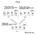
- Fig. 2 is a view for explaining the concept of an encoding method.
- the hierarchical encoding method uses one lower-layer (lower level) and two upper layers (higher levels).
- a selected area hatchched area
- L(t) A remarkable time is denoted by t and a decoded image of the time t is denoted by L(t).
- H1(t) A decoded image of this layer
- predictive coding is made by using the decoded image of the lower-layer L(t) and the decoded image of the first upper-layer H1(t-1).
- the selected area is predictively encoded to be of a higher image-quality than that at the lower-layer.
- the decoded image of this layer is denoted by H2(t).
- predictive coding is made by using decoded image of the lower-layer L(t) and the decoded image of the second upper-layer H2(t-1).
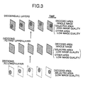
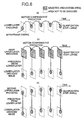
- Figs. 3 and 4 are illustrative of the concept of a decoding method.
- Fig. 3 shows three-layer decoding processes: decoding only lower-layer data, decoding only the first upper-layer data and decoding all layers data.
- decoding the lower-layer data reproduces only an image selected by the coding device to be of a relatively low image-quality
- decoding the first upper-layer data reproduces a whole image of a relatively low image-quality
- decoding all coded data reproduces the selected area of a higher image-quality and all other areas of a lower image-quality.
- Fig. 4 shows a case when all coded signals are decoded after decoding the second upper-layer data instead of the first upper-layer data. In this case, an intermediate layer (the second upper-layer) data is decoded to reproduce a selected image-area only of a higher image-quality.
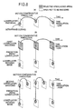
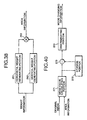
- Fig. 5 is a block diagram showing a coding device.
- an area selecting portion 5 and an area-position-and-shape coding portion 6 are similar in function to those of the prior art shown in Fig. 1.
- an lower-layer coding portion 4 encodes only an area selected by the area selecting portion 5 to be of a lower image-quality, prepares coded data of the rower-layer and generates a decoded image from the coded data.
- the decoded image is used as a reference image for predictive coding.
- a first-layer coding portion 1 encodes a whole image to be of a lower image-quality, prepares coded data of the first-layer and generates a decoded image from said coded data.
- the decoded image is used as a reference image for predictive coding.
- a second-layer coding portion 2 encodes only a selected area image to be of a higher image-quality, prepares coded data of the second-layer and generates a decoded image from said coded data.
- the decoded image is used as a reference image for predictive coding.
- a coded data integrating portion 3 integrates selected-area position-and-shape codes, lower-layer coded data, first upper-layer coded data and second upper-layer coded data.
- Figs. 6 and 7 are illustrative of the technique of controlling the lower-layer image-quality and the upper-layer image quality depending upon quantization steps.
- Fig. 6(a) illustrates how to encode the lower-layer image data.
- a hatched area represents a selected area.
- a selected area of a first frame is intraframely encoded and selected areas of other remaining frames are predictively encoded by motion-compensative prediction method.
- As a reference image for the motion compensative prediction is used a selected area of a frame of the lower-layer, which has been already encoded and decoded.
- forward prediction is shown in Fig. 6(a), it may be applied in combination with backward prediction.
- the quantization step at the lower-layer is controlled to be larger than that at the second upper layer, only a selected area of an input image is encoded to be of a lower image-quality (with a low signal-to-noise ratio). Consequently, the lower-layer image-data is encoded by using a smaller amount of codes.
- Fig. 6(b) illustrates how to encode the first upper-layer image data.
- a whole image is encoded.
- a whole image is encoded by predictive coding based on a decoded image of the lower-layer and a decoded image of the first upper-layer.
- a whole image of the first frame is encoded by prediction from the lower-layer decoded image (areas other than selected one are intraframely encoded in practice because the motion-compensative prediction method can not be applied in practice).
- Other frames can be encoded by using the predictive coding in combination with the motion compensative prediction.
- Such a variation is also applicable, which does not encode a selected area and encodes only other areas by the predictive coding method as shown in Fig. 6.
- the encoding process is performed for areas other than the selected one.
- Fig. 6(c) illustrates how to encode the second upper-layer image data. Only a selected image area is encoded at a relatively small quantization step.
- objective data to be encoded is differential data obtained between original image data and image data predicted from the lower-layer image data. Although only prediction from the lower-layer image data is shown in Fig. 6(c), it may be used in combination with the prediction from a decoded frame of the second upper-layer.
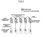
- Fig. 8 is a view for explaining a method of controlling the lower-layer image quality and the upper-layer image quality by using differential time resolution values.
- Fig. 8(a) illustrates how to encode the lower-layer image data.
- a hatched area represents a selected area.
- a selected area of a first frame is intraframely encoded and selected areas of other remaining frames are predictively encoded by motion-compensative prediction.
- As a reference image for the motion compensative prediction is used a selected area of a frame of the lower-layer, which has been already encoded and decoded.
- forward prediction is shown in Fig. 8(a), it may be applied in combination with backward prediction.
- the frame-rate of the lower-layer is so decreased that time resolution is adjusted to be lower than that at the second upper layer. It is also possible to encode frames at a smaller quantization interval so that each frame may have a larger signal-to-noise ratio.
- Fig. 8(b) illustrates how to encode the first upper-layer image data.
- a whole image is encoded with a low time-image-resolution.
- Fig. 8(c) illustrates how to encode the second upper-layer image data. Only a selected area is encoded with a higher time resolution. In this case, a frame whose selected area was encoded at the lower-layer is encoded by prediction from the lower-layer decoded image, whereas all other frames are encoded by motion compensative prediction from the already decoded frames of the upper-layer. In case of using prediction from the lower-layer decoded frame, it is possible not to encode any second upper-layer image data, adopting the lower-layer decoded image as a second upper-layer decoded image.
- Fig. 9 is a view for explaining a method of the lower-layer image quality and the upper-layer image quality by using differential spatial resolution values.
- Fig. 9(a) illustrates how to encode the lower-layer image data.
- An original image is converted into an image of a lower spatial resolution through a low-pass filter or thinning operation. Only hatched selected areas are encoded.
- a selected area of a first frame is intraframely encoded and selected areas of other remaining frames are predictively encoded by motion-compensative prediction.
- Fig. 9(b) illustrates how to encode the first upper-layer image data.
- An original image is converted into an image of a lower spatial resolution and a whole image is encoded with a higher time-resolution.
- Fig. 9(c) illustrates how to encode the second upper-layer image data. Only a selected area is encoded with a higher spatial resolution. In this case, a decoded image of the lower-layer is converted into an image having the same spatial resolution as an original image and selected areas are encoded by prediction from the lower-layer decoded image and by motion compensative prediction from the already decoded frame of the second upper-layer.
- a selected area in a whole image is thus encoded to have a higher image-quality than that of other areas.
- the coded data is given respective one of three hierarchical layers (two upper layers and one lower-layer).
- Fig. 10 is illustrative of a first decoding device, which is intended to decode only lower-layer image data.
- a coded data separating portion 7 is intended to separate coded data into area-position-and-shape coded data and lower-layer coded image data and selectively extract desired coded data.
- An area-position-and-shape decoding portion 9 is intended to decode a position code and a shape code of a selected area.
- An lower-layer decoding portion 8 is intended to decode lower-layer coded data of a selected area and to prepare a lower-quality decoded image of the selected area only.
- each image outputted from this decoding device relates to image information of a selected area only, which is indicated as a window on a display screen.
- the lower-layer decoding portion 8 may be provided with a spatial resolution converter to enlarge the select area to full screen size and indicate it on the display screen.
- the shown decoding device embodiment may obtain decoded images of a lower quality because of decoding only lower-layer data of a selected area, but it may be simple in hardware construction omitting an upper-layer decoding portion and may easily decode the coded image by processing an decreased amount of the coded data.
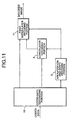
- Fig. 11 is illustrative of a second decoding device wherein an area-position-and-shape decoding portion 9 and an lower-layer decoding portion 8 are similar in function to those of the first decoding device.
- a coded data separating portion 10 separately extracts, from coded data, area-position-and-shape coded data, lower-layer coded data of an area and first upper-layer coded data.
- a first upper-layer decoding portion 11 decodes a first upper-layer coded data, whereby a whole image is decoded to be of a lower quality by using area-position-and-shape data, the lower-layer decoded image and the second upper-layer decoded image. A first upper-layer decoded image is thus prepared.
- the shown device uses the first upper-layer coded data, it may also use the second upper-layer instead of the first upper-layer.
- the coded data separating portion 10 separately extracts, from coded data, area-position-and-shape coded data, lower-layer coded data of an area and second upper-layer coded data.
- the first upper-layer decoding portion 11 is replaced by a second upper-layer decoding portion which decodes a second upper-layer coded data by using the area-position-and-shape data, the lower-layer decoded image and the second upper-layer decoded image and only the selected image is decoded to be of a higher quality.
- a second upper-layer decoded image thus prepared may be displayed as a window on a display screen or be enlarged to full-screen size and then displayed thereon.
- Fig. 12 is illustrative of a third decoding device, wherein an area-position-and-shape decoding portion 9 and an lower-layer decoding portion 8 are similar in function to those shown in Fig. 2.
- a coded data separating portion 10 separately extracts, from coded data, area-position-and-shape data, lower-layer coded data, first upper-layer coded data and second upper-layer coded data.
- a first upper-layer decoding portion 11 decodes a first upper-layer coded data
- a second upper-layer decoding portion 13 decodes a second upper-layer coded data
- An upper-layer synthesizing portion 14 combines a second upper-layer decoded image with a first upper-layer decoded image to produce a synthesized image by using information on the area position and shape.
- the synthesis of a selected area is conducted by using the second upper-layer decoded image, while the synthesis of other areas is conducted by using the first upper-layer decoded image. Therefore, an image outputted from the decoding device relates to a whole image wherein a selected area is particularly decoded to be of a higher quality as to parameters such as SNR (Signal-to-Noise Ratio), time resolution and spatial resolution.
- SNR Signal-to-Noise Ratio
- An area selected by the coding device is thus decoded to have a higher quality than that of other areas.
- Fig. 13 is a block diagram showing a conventional device as a reference.
- a first video-sequence is assumed to be a background video and a second video-sequence is assumed to be a part video.
- An alpha plane is weight data used when synthesizing a part image with a background image in a moving picture (video) sequence.
- Fig. 14 shows an exemplified image made of pixels weighted with values of 1 to 0.
- the alpha-plane data is assumed to be 1 within a part and 0 out of a part.
- the alpha data may have a value of 0 to 1 in a boundary portion between a part and the outside thereof in order to indicate a mixed state of pixel values in the boundary portion and transparency of transparent substance such as glass.
- a first video-coding portion 101 encodes the first video-sequence and a second video-coding portion 102 encodes the second video-sequence according to an international standard video-coding system, e.g., MPEG or H.261.
- An alpha-plane coding portion 112 encodes an alpha-plane.
- this portion uses the techniques of vector quantization and Haar transformation.
- a coded-data integrating portion (not shown) integrates coded data received from the coding portions and accumulates or transmits the integrated coded data.
- a coded-data dissembling portion (not shown) disassembles coded data into the coded data of the first video-sequence, the coded data of the second video-sequence and the coded data of the alpha-plane, which are then decoded respectively by a first video-decoding portion 105, a second video-decoding portion 106 and an alpha-plane decoding portion 113.
- Two decoded sequences are synthesized according to weighted mean values by a first weighting portion 108, a second weighting portion 109 and adder 111.
- (x,y) represents coordinate data of an intraframe pixel position
- t denotes a frame time
- f1(x,y,t) represents a pixel value of the first video sequence
- f2(x,y,t) represents a pixel value of the second video sequence
- f(x,y,t) represents a pixel value of the synthesized video sequence
- ⁇ (x,y,t) represents alpha-plane data.
- the first weighting portion 108 uses 1- ⁇ (x,y,t) as a weight while the second weighting portion 109 uses ⁇ (x,y,t) as a weight.
- the conventional method produces a large number of coded data because it must encode alpha-plane data.
- Fig. 15 is a block diagram showing a coding device and decoding device embodying the present invention.
- a first video-coding portion 101, a second video-coding portion 102, a first video-decoding portion 105, a second video-decoding portion 106, a first weighting portion 108, a second weighting portion 109 and adder 111 are similar in function to those of the conventional device and, therefore, will not be further explained.
- an area-information coding portion 103 encodes an area information representing a shape of a part image of a second video-sequence
- an area-information decoding portion 107 decodes the coded area-information
- an alpha-plane generating portion 110 prepares an alpha plane by using coded area information.
- the operations of the coding device and the decoding device are as follows:
- the coding device encodes the first video-sequence and the second video-sequence by the first video-coding portion 101 and the second video-coding portion 102 respectively and encodes an area information by the area-information coding portion 103 according to a method to be described later. These coded data are integrated for further transmission or accumulation by a coded-data integrating portion (not shown). On the other hand, the decoding device separates the transmitted or accumulated coded data by the coded-data separating portion (not shown) and decodes the separated coded data by the first video-decoding portion 105, the second video-decoding portion 106 and the area-information decoding portion 107 respectively.
- the alpha-plane generating portion 110 prepares an alpha-plane from the decoded area-information by a method to be described later.
- the first weighting portion 108, the second weighting portion 109 and the adder 111 may synthesize two decoded sequences by using weighted mean values according to the prepared alpha-plane.
- Fig. 16 shows an example of area information that corresponds to an area information of a part video-image of Fig. 14.
- the area information is binarized using a threshold of 0.2. Area information may be thus obtained by binarizing the alpha plane or it may be determined by edge detection or other area-dividing method. In case of selecting an area by a method described in a reference material "Real-time face-image following-up method" (The Institute of Image Electronics Engineers of Japan, Previewing Report of Society Meeting, 93-04-04, pp. 13-16, 1993), information to be used may be a rectangle. In this instance, area information is binarized, e.g., as 1 within a body and as 0 outside the body.
- a practical technique of encoding area information may be run-length coding and chain coding since the area information is binarized data. If area data represents a rectangle, it requires encoding only coordinate data of its start point, length and width.
- an alpha-plane can be prepared by independently using the following linear weight-values in horizontal direction and vertical direction of the rectangle area.
- M is equal to “aN” and L is equal to "N-M" ("a” is a real value of 0 to 1).
- N represents a size of a rectangle area and "a” represents flatness of weight to be applied to said area.
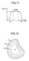
- Fig. 17 shows an example of a linear function of weight.
- a size of the rectangle is expressed by the number of pixels "Nx” in horizontal direction and pixels “Ny” in vertical direction and the flatness of weight is expressed by "ax” in horizontal direction and by “ay” in vertical direction.
- the first method is to determine a circumscribed rectangle of the area and then to apply the above-mentioned linear weight functions to the circumscribed rectangle in horizontal direction and vertical direction respectively.
- the second method is to sequentially determine weight values to be applied to an area from its circumference as shown in Fig.18. For example, pixels at the circumference of the area are determined and are given a weight of 0.2 respectively. Next, pixels at the circumference of a still-not-weighted part within the area are determined and are given a weight of 0.5 respectively. These operations are repeated until circumferential pixels are weighted at 1. Preparation of an alpha-plane is finished by applying a weight of 1.0 to a last not-weighted area. The obtained alpha-plane has a value of 1.0 at its center portion and a value of 0.2 at its circumferential portion.
- a circumferential pixel thickness may be a single pixel or more.
- the third method is to apply a weight of 0 to the outside of an area and a weight of 1 to the inside of the area and then to process a thus binarized image through a low-pass filter to gradate the area boundary portion.
- Various kinds of alpha-planes can be prepared by changing a size and coefficient of a filter and the number of filtering operations.
- the first embodiment can attain an increased efficiency of data coding in comparison with the conventional device because the alpha-plane is prepared by the decoding side, thereby eliminating the need of encoding weight-information.
- the decoding device prepares an alpha-plane from the decoded area information and synthesizes video-sequences by using the prepared alpha-plane, thereby preventing the occurrence of such a visual defect that a toothed line appears at the boundary of a part image in the background.
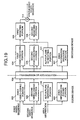
- Fig. 19 is a block diagram showing a coding device and a decoding device of the embodiment.
- a first weighting portion 108, a second weighting portion 109 and adder 111 are similar to those of the conventional device and is omitted from the further explanation.
- An area-information coding portion 103, an area-information decoding portion 107, alpha-plane generating portions 121 and 122 are similar in function to those of the first embodiment and, therefore, will not be further explained.
- This embodiment is featured in that the coding side is also provided with an alpha-plane generating portion 120 for encoding an image with weight values for synthesizing a plurality of video sequences. Coded data becomes smaller than the original data because weight data is not more than 1, and, therefore, an amount of coded data can be reduced.
- a first video-coding portion 122 and a second video-coding portion 123 encode images of video-sequences by weighting on the basis of respective alpha-planes prepared by the coding side.
- a first video-decoding portion 124 and a second video-decoding portion 125 decode the coded images of the video-sequences by inversely weighting on the basis of respective alpha-planes prepared by the decoding side.
- the first video-coding portion 122 or the second video coding portion 123 may be constructed for transform-coding as shown, for example, in Fig. 20.
- a video-sequence to be processed is the first video-sequence or the second video-sequence.
- a transforming portion 131 transforms an input image by block by using a transforming method such as DCT (Discrete Cosine Transform), discrete Fourier transform and Weiblet transform.
- DCT Discrete Cosine Transform
- a first weighting portion 132 weights a transform-coefficient with an alpha-plane value.
- the value used for weighting may be a representative of an alpha-plane within an image block to be processed. For example, a mean value of the alpha-plane within the block is used.
- gw1(u,v) and gw2(u,v) denote weighted transform coefficients
- u and v denote horizontal and vertical frequencies
- ⁇ is a representative of an alpha-plane in a block.
- a quantizing portion 133 quantizes transform coefficients
- a variable-length coding portion 134 encodes the quantized transform coefficients with variable-length codes to generate coded data.
- a first video-decoding portion 124 or a second video-decoding portion 125 which corresponds to the video-decoding portion of Fig. 19, may be constructed as shown in Fig. 21.
- a variable-length decoding portion 141 decodes coded data
- an inversely quantizing portion 142 inversely quantizes decoded data
- g 2(u,v) g w2(u,v)/ ⁇
- ⁇ (Hat) indicates decoded data, e.g., gw1 with a hat is a weighted decoded transform coefficient of the first video-sequence.
- weighting is substantially effected by correcting a quantizing-step width adopted by the international standard MPEG or H.261 by using a representative value of the alpha-plane within the block.
- a quantizing-step width changing portion 138 is provided as shown in Fig. 22, whereby a quantizing-step width determined by a quantizing-step width determining portion (not shown) is changed by using alpha-plane data.
- a representative ⁇ e.g., a mean value
- the quantizing-step width is divided by a value (1 - ⁇ ) for the first video sequence or by a value ⁇ for the second video-sequence to obtain a new quantizing-step width.
- the first method relates to a case when a quantizing-step width (without being changed by the quantizing-step width changing portion 138) is encoded by the coding device shown in Fig. 22.
- the decoding device of Fig. 23 which is provided with a quantizing-step width changing portion 148 corresponding to that of the coding side of Fig. 22, decodes the quantizing-step width by a quantizing-step width decoding portion (not shown) and then changes the decoded quantizing-step width by the quantizing-step width changing portion 148 according to the alpha-plane data.
- the second method relates to a case when a quantizing-step width after being changed by the quantizing-step width changing portion 138 is encoded by the coding device shown in Fig. 22.
- the decoding device directly uses the decoded quantizing-step width and inversely quantizes it. This eliminates the use of a special inversely weighting device (i.e., the quantizing-step width changing portion 148 of Fig. 23).
- the second method is considered to have a decreased flexibility of weighting as compared with the first method.
- the above-described second embodiment uses the transform coding. Therefore, a motion compensative coding portion featuring the MPEG system or the H.261 system was omitted from Figs. 20 to 23. This method, however, can be applied for coding system using the motion compensative prediction. In this instance, a prediction error for motion compensative prediction is inputted into a transforming portion 131 of Fig. 20.
- Fig. 24 shows an example of the first video-coding portion 122 or the second video-coding portion 123 of the coding device shown in Fig. 19.
- fw1(x,y) is the first weighted video-sequence
- fw2(x,y) is the second weighted video-sequence
- ⁇ is a representative of an alpha-plane within a block.
- Fig. 25 shows an inversely weighting method of the decoding device, which corresponds to the above-mentioned weighting method.
- the inversely weighting portion 161 weights the video-sequence with weight reversing that applied by the coding device.
- the decoding device may omit the inversely weighting portion 161, the first weighting portion 108 and the second weighting portion 109 for synthesizing sequences, which are shown in Fig. 19. Namely, it is possible to use a coding device and decoding device, which are shown in Fig. 26.
- a first video-coding portion 122 and a second video-coding portion 123, which are shown in Fig. 26, are constructed as shown in Fig. 24, and use the weighting method of equation (5).
- weight information such as area information and alpha-plane data, which are necessary for synthesizing the video-sequences, is included in the video coded data itself, the weighting information does not require encoding. Accordingly, sequences decoded by the decoding device can be directly added to each other to generate a synthesized sequence. Encoding only data within an area is rather more effective than encoding a whole image if a video-sequence 102 relates to a part image. In this case, it becomes necessary to encode the area information by the coding device and to decode the coded area information by the decoding device.
- the foregoing description relates to an example of weighting each of plural video-sequences in the second embodiment of the present invention.
- the first video-sequence is weighted with a value of (1- ⁇ ) while the second video-sequence is weighted with a value of ⁇ .
- each area information corresponding to each part image is encoded.
- the background image and part images may be independently encoded or may be hierarchically encoded, considering the background image as an lower-layer and the part images as upper-layers. In the latter case, each upper-layer image can be effectively encoded by predicting its pixel value from that of the lower-layer image.
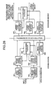
- the synthesizing device of Fig. 32 is intended to solve a problem that may occur in a synthesizing portion 205 shown in Fig. 28.
- This video-synthesizing device is capable of synthesizing an image from two lower-layer decoded frames and one upper-layer decoded selected area or areas without occurrence of afterimage-like distortion around the selected area or areas.
- Fig. 32 is a block diagram showing the image synthesizing device.
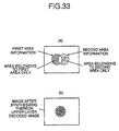
- a first area-extracting portion 221 is to extract an area, which relates to a first area and does not relate to a second area, from a first area information of an lower-layer frame and a second area information of an lower-layer frame.
- the first area information is shown by a dotted line (0 within the dotted area and 1 outside the dotted area) and the second area information is shown by a broken line (with similar numeral codes). Consequently, an area to be extracted by the first area extracting portion 221 is a hatched part shown in Fig. 33.
- a second area extracting portion 222 of Fig. 32 is intended to extract an area, which relates to the second area and does not relate to the first area, from a first area information of an lower-layer frame and a second area information of an lower-layer frame. Namely, a dotted area shown in Fig. 33(a) is extracted.
- a controller 223 controls a switch 224 according to an output of the first area extracting portion and the second area extracting portion.
- the switch 224 is connected to a second decoded image side when the position of a remarkable pixel relates to only the first area and it is connected to a first decoded image side when the remarkable pixel relates to only the second area.
- the switch is connected to an output of interpolation-image generating portion 225 when the remarkable pixel does not relate to the first and second areas.
- the interpolation-image generating portion 225 calculates an interpolating image between the first decoded lower-layer image and the second decoded lower-layer image according to the equation (1) defined as the above.
- the first decoded image is expressed as B(x, y, t1)
- the second decoded image is expressed as B(x, y, t2)
- the interpolating image is expressed as B(x, y, t3).
- "t1", "t2" and "t3" are time marks of the first decoded image, second decoded image and interpolating image respectively.
- the interpolating image thus generated is featured by that the hatched area is filled with a background image, outside the selected area, of the second decoded frame, a dotted area is filled with a background image, outside the selected area, of the first decoded frame, and other portions are filled with the interpolating image between the first and second decoded frames.
- the upper-layer decoded image is then overlaid on the above-mentioned interpolating image by the weighted averaging portion 226 shown in Fig. 32 to produce a synthesized image shown in Fig. 33(b), which has no after image around the selected (hatched) area and is free from the distortion occurred in the prior art image.
- the weighted averaging portion 226 combines the interpolating image with the upper-layer decoded image by using weighted means. The weighted averaging method was described before.
- t1, t2 and t3 denote time marks of the first decoded image, the second decoded image and the upper-layer decoded image.
- Fig. 34 is a block diagram showing a device for predicting a motion parameter and modifying area information of two corresponding frames.
- a motion-parameter estimating portion 231 estimates information about the motion from a first lower-layer decoded image to a second lower-layer decoded image by determining motion parameters, e.g., motion vector per block and a whole image movement (parallel displacement, rotation, enlargement and contraction).
- An area-form modifying portion 232 modifies the first decoded image, the second decoded image, the first area information and the second area information according to respective predicted motion parameters based on the temporal positions of the synthesizable frames. For example, a motion vector (MVx,MVy) from the first decoded image to the second decoded image will be determined as a motion parameter. MVx is a horizontal component and MVy is a vertical component. A motion vector from the first decoded image to the interpolating image is determined according to the equation: (t3-t1)/(t2-t1)(MVx,MVy). The first decoded image is then shifted according to the obtained vector.
- the image is not only shifted but also be deformed.
- These data sets are inputted into the image synthesizing device shown in Fig. 32, which generates a synthesized image.
- the above-described device predicts the motion parameters from two decoded images, it may also use a motion vector of each block of each image, which is usually included in coded data prepared by predictive coding.
- a mean value of the decoded motion vectors may be applied as a motion vector of a whole image from the first decoded frame to the second decoded frame. It is also possible to determine a frequency distribution of decoded motion vectors and to use a vector of highest frequency as a motion parameter of a whole image from the first decoded frame to the second decoded frame.
- the above-mentioned processing is performed independently in a horizontal direction and a vertical direction.
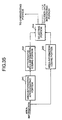
- Figs. 35 and 36 are block diagrams of a system whose coding side is shown in Fig. 35 and decoding side is shown in Fig. 36.
- an area-information approximating portion 241 approximates an area information by using a plurality of geometrical figures.
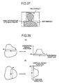
- Fig. 37 shows an example of approximation of an area information of a human figure (hatched portion) with two rectangles. One rectangle 1 represents a head of a person and the other rectangle 2 represents a breast portion of the person.
- An approximated-area information coding portion 242 encodes the approximated area-information.
- An area approximated by rectangles as shown in Fig. 37 may be encoded with a fixed code length by encoding coordinates of a left top point of each rectangle and a size of each rectangle with a fixed code length.
- An area approximated by an ellipse may be encoded at a fixed code length by encoding coordinates of its center, long axis length and short axis length. The approximated area-information and the coded data are sent to a selecting portion 244.
- an area-information coding portion 243 of Fig. 35 encodes an area-information by using an 8-directional quantizing code without approximation.
- the area information and the coded data are sent to a selecting portion 244.
- the selecting portion 244 selects either one of two outputs 242 and 243.
- the coded data of the approximated area information with single-bit (e.g., 1) selection information is sent to a coded-data integrating portion (not shown) and approximated area information is sent to a synthesizing portion (not shown).
- the coded data of the not-approximated area information with one bit (e.g., 1) of selection information is sent to a coded-data integrating portion (not shown) and the not-approximated area information is sent to a synthesizing portion according to the present invention.
- the selecting portion may operate, for example, to select an output which may produce smaller amount of coded data or to select the output 244 when an amount of coded data of the not-approximated information does not exceed a threshold value and the output 242 when said amount exceeds said threshold value. This makes it possible to reduce the amount of coded data, preventing the area information from being distorted.
- a selecting portion 251 selects which kind of area-information - approximated or not-approximated - according to the single-bit selecting information contained in the received coded data.
- an approximated-area-information decoding portion 252 decodes the approximated area information
- an area-information decoding portion 253 decodes the not-approximated area information.
- a switch 254 is controlled by a signal from the selecting portion 251 to select an approximated area-information or not-approximated area-information as an output to a synthesizing portion.
- Either approximated area information or not-approximated area information is thus adaptively selected, encoded and decoded.
- the approximated area-information is selected to encode the area-information with a small amount of information.
- the not-approximated area information is encoded by using 8-directional quantizing codes, but it may be more effectively encoded by using a combination of 8-directional quantization with predictive coding.
- An 8-directional quantizing code takes 8 values from 0 to 7 as shown in Fig. 30, which are differentiated to be from -7 to 7 by predictive coding.
- a difference may be limited to a range of -3 to 4 by adding 8 if the difference being -4 or less and by subtracting 8 if the difference is more than 4.
- an original 8-directional quantization value can be obtained by first adding the difference to the precedent value and then by subtracting or adding 8 when the result is negative value or exceeds 7.
- a difference between a quantization value 6 and a precedent value is 5 from which 8 is subtracted to obtain a result of -3.
- decoding -3 is added to the precedent value 1 and a value -2 is obtained, which is negative and therefore is increased by adding 8 thereto to finally obtain a decoded value 6.
- Such predictive coding is effected by utilizing the cyclic feature of the 8-directional coding.
- this device encodes an approximated area-information of each image independently, it is possible to increase the efficiency of coding using the preceding coding result because video frames usually have a high interframe correlation. Namely, only a difference of approximated area information of ,two successive frames is encoded if the approximated area information is continuously encoded between two frames.
- a rectangle of a preceding frame is expressed by its left-top position (19, 20) and size (100, 150) and a rectangle of a current frame is expressed by its left-top position (13, 18) and size (100, 152)
- a differential left-top position (3, 2) and differential size (0, 2) of the current frame is encoded.
- an amount of coded data for the area information can be considerably saved by using entropy coding, e.g., Huffman coding because differences concentrate near to 0 at a small change of an area shape.
- entropy coding e.g., Huffman coding
- Another embodiment of the present invention is as follows:
- This embodiment relates to a weight-information generating device for preparing many-valued weight information from an area information.
- Fig. 38 is a block diagram of this embodiment.
- a horizontal weight generating portion 261 horizontally scans an area information and detects 1 therein, then calculates a corresponding weight function.
- the abscissa x0 of a left-end point and the horizontal length N of the area are first determined and then a horizontal weight function is calculated as shown in Fig. 39(a).
- the weight function may be prepared by combining straight lines or by combining a line with a trigonometric function. An example of the latter case is described below. If N > W (W is a width of a trigonometric function), the following weight functions may be applied:
- a vertical weight generating portion 262 vertically scans the area information and detects 1 therein, then calculates a corresponding vertical weight function.
- the ordinate y0 of a top-end point and the vertical length M of the area are determined, then a vertical weight function is calculated as shown in Fig. 39(b).
- a multiplier 263 multiplies an output 261 by an output 262 at each pixel position to generate a weight information.
- the above-mentioned method may obtain a weight information adapted to the form of the area information with a reduced number of operations.
- Fig. 40 is a block diagram of a device performing this method.
- a mean-value calculating portion 271 determines a mean of pixel values in an area according to an input original image and an input -area-information.
- the mean value is inputted into a differentiator 273 and a storage 272.
- the differentiator 273 determines a' difference between a preceding mean value stored in the storage 272 and a current mean value outputted from the mean-value calculating portion 271.
- a discriminating portion 274 compares an absolute value of the difference calculated by the differentiator 273 with a predetermined threshold value and outputs a mode-selecting information. With the absolute value of the difference being larger than the threshold, the discriminating portion 273 judges that a scene change occurs in a selected area and generates a mode selecting signal to always conduct the intraframe prediction coding.
- Mode selection thus effected by judging a scene change of a selected area is effective to obtain high-quality coded images even when, for example, a person appears from behind the cover or any matter is turn over.
- the shown embodiment can be applied for system for coding a selected area separately from other areas in encoding lower-layer frames. In this case, area information is inputted into the lower-layer coding portion. This embodiment can be also applied for coding only a'selected area of the upper-layer frame.
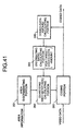
- Fig. 41 is a block diagram of a device performing this method.
- a coding portion 283 separates a selected area from other areas and encodes it.
- An area discriminating portion 281 receives an area information and discriminates whether the encodable area is within or outside the selected area.
- a coded-data-amount estimating portion 285 estimates an amount of coded data in each area on the basis of the above-mentioned discrimination result.
- a distributing ratio calculating portion 284 determines distributing ratios of a target amount of codes per frame, which will be allocated to areas. The method for determining distributing ratios will be described later.
- a quantizing width calculating portion determines a quantizing step-size according to the target amount of coded data. The method for determining quantizing step-size is the same as the conventional method.
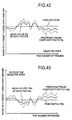
- the method for determining a code distributing ratio by the target code-allocation calculating portion is as follows:
- This target number Bi of bits is distributed at a specified ratio to pixels within a selected area and pixels outside the selected area.
- the ratio is determined by using an adequate fixed ratio RO and a preceding frame complexity ratio Rp.
- Fig. 42 there are two exemplified curves plotted by dotted lines, which represent the fixed ratio RO and the preceding frame complexity ratio Rp in a selected area for a whole video sequence.
- a solid-line curve of Fig. 42 relates to the obtainable ratio Ra for distributing a target coded-data-amount, which does not so far part from the curve of fixed ratio and reflects, to a certain extent, a change of an image in a video sequence.
- an average ratio which is a target-bit-amount distributing ratio (1-Ra) for pixels outside the selected area, takes a solid-line-plotted curve shown in Fig. 43.
- a total of two target-bit-amount distributing ratios for pixels in and out of a selected area takes 1.
- the quantization step-size can be thus adaptively controlled.
- a bit rate of a whole video sequence may some time exceed a predetermined value because the number of bits used exceeds the target value Bi in some frames. In this case, the following method may be applied.
- the target-bit-amount distributing ratio Ra for coding pixels in a selected area is a mean value of the fixed ratio RO and the preceding complexity ratio Rp
- the target-bit-amount distributing ratio Rm for coding pixels outside the selected area is a minimal value Rm of the fixed ratio (1-RO) and preceding frame complexity ratio (I-Rp) for coding pixels outside the selected area.
- the target-bit-amount distributing ratio (1-Ra) for coding pixels outside the selected area may vary, for example, as shown by a solid line in Fig. 44.
- Ra + Rm ⁇ 1 the target number of bits can be reduced for a frame or frames wherein excess bits may occur.
- the bit rate of a whole video sequence may be kept within the predetermined limit by reducing the target bit-amount of a background area of a frame or frames.
- decoding upper-layer coded data it is possible to select which the first upper-layer or the second upper-layer is decoded. A whole image is decoded to be of a lower image-quality if the first layer is selected, whereas only a selected area is decoded to be of a high image-quality if the second upper-layer is selected.
- an image In decoding all coded data, an image can be decoded in such a way that a selected area of the image may have a higher image quality than that of all other areas thereof.
- the above-described decoding device receives all coded data
- a decoding terminal requests a coding side to send a limited data, e.g., coded data on an area position and shape, coded data of the lower-layer and coded data of the first layer to communicate over a transmission line of a narrow bandwidth.
- the present invention realizes such data communication that transmits only the lower-layer data over a transmission line of a very narrow bandwidth or selectively transmits any one of two kinds of upper-layer data over a line of some wider bandwidth or transmits all kinds of data over a line of further wider bandwidth.
- weighted mean information is prepared from binarized information inputting a plurality of part video-sequences onto a background video-sequence by using the weighted mean values. Because the weighted mean data prepared from the binarized information gets a value of 0 to 1, a boundary between the part images and the background images can be smoothly synthesized without occurrence of any visual defect.
- the amount of coded data can be reduced or the quality of decoded image can be improved at the same amount of the coded data as compared with the prior art devices.
Claims (7)
- Dispositif de codage vidéo comprenant :un premier moyen de codage (122 ; 131 à 134) pour coder une séquence vidéo pour une vidéo d'arrière-plan,un second moyen de codage (123 ; 131 à 134) pour coder une séquence vidéo d'au moins une partie d'une image de premier plan ; etun moyen de codage d'informations de zone (103) pour coder des informations de zone binaires représentant une forme d'une vidéo partielle, caractérisé en ce que le dispositif est muni de plus d'un moyen de préparation de données de pondération (120 ; 261, 262, 263) pour la préparation de données de pondération à multiples valeurs à partir des informations de zone binaires et donne un poids à chacune des séquences vidéo selon lesdites données de pondération à multiples valeurs.
- Dispositif de codage vidéo selon la revendication 1, caractérisé en ce qu'une valeur représentative des données de pondération pour chaque bloc codé est déterminée et chacune des séquences vidéo est pondérée sur la base de la valeur représentative correspondante des données de pondération.
- Dispositif de codage vidéo selon la revendication 1, caractérisé en ce que lesdits premier et second moyens de codage sont chacun conçus pour transformer et coder la séquence vidéo respective, et en ce qu'une valeur représentative des données de pondération pour chaque bloc transformé et codé est déterminée et chacune des séquences vidéo transformées est pondérée sur la base de la valeur représentative correspondante des données de pondération.
- Dispositif de codage vidéo pour le décodage de données codées préparées par le dispositif de codage vidéo de la revendication 1, comprenant :un premier moyen de décodage (124 ; 141 à 144) pour décoder une séquence vidéo pour une vidéo d'arrière-plan ;un second moyen de décodage (125 ; 141 à 144) pour décoder une séquence vidéo d'au moins une partie d'une image de premier plan ;un moyen de décodage d'informations de zone (107) pour décoder des informations de zone binaires représentant une forme d'une vidéo partielle ;un moyen de préparation de données de pondération (121 ; 261, 262, 263) pour la préparation de données de pondération à multiples valeurs à partir des informations de zone binaires décodées ;un moyen de pondération (108, 109) pour la pondération de chaque séquence vidéo avec un poids inverse de celui donné par le dispositif de codage vidéo de la revendication 1 ; etun moyen de synthèse (111) pour faire la synthèse de chaque séquence vidéo pondérée par le moyen de pondération.
- Dispositif de codage vidéo selon la revendication 4, caractérisé en ce qu'une valeur représentative des données de pondération pour chaque bloc décodé est déterminée et chacune des séquences vidéo est pondérée sur la base de la valeur représentative correspondante des données de pondération.
- Dispositif de codage vidéo selon la revendication 4, caractérisé en ce que lesdits premier et second moyens de décodage sont chacun conçus pour décoder et transformer la séquence vidéo respective, et en ce qu'une valeur représentative des données de pondération pour chaque bloc transformé et décodé est déterminée et chacune des séquences vidéo transformées est pondérée sur la base de la valeur représentative correspondante des données de pondération.
- Système de codage et décodage vidéo comprenant :caractérisé en ce que le dispositif de décodage vidéo est muni de plus d'un moyen de préparation de données de pondération (121 ; 261, 262, 263) pour préparation de données de pondération à multiples valeurs à partir des informations de zone binaires décodées, un moyen de pondération (108, 109) pour la pondération de chaque séquence vidéo avec lesdites données de pondération à multiples valeurs, et un moyen de synthèse (111) pour faire la synthèse de chaque séquence vidéo pondérée par le moyen de pondération.un dispositif de codage vidéo ayant un premier moyen de codage (122 ; 131 à 134) pour coder une séquence vidéo pour une vidéo d'arrière-plan, un second moyen de codage (123 ; 131 à 134) pour coder une séquence vidéo d'au moins une partie d'une image de premier plan, et un moyen de codage d'informations de zone (103) pour coder des informations de zone binaires représentant une forme d'une vidéo partielle ; etun dispositif de décodage vidéo ayant un premier moyen de décodage (124 ; 141 à 144) pour décoder une séquence vidéo pour une vidéo d'arrière-plan, un second moyen de décodage (125 ; 141 à 144) pour décoder une séquence vidéo d'au moins une partie d'une image de premier plan et un moyen de décodage d'informations de zone (107) pour décoder des informations de zone binaires représentant une forme d'une vidéo partielle ;
Applications Claiming Priority (7)
| Application Number | Priority Date | Filing Date | Title |
|---|---|---|---|
| JP17864395 | 1995-07-14 | ||
| JP17864295 | 1995-07-14 | ||
| JP17864295A JP3098939B2 (ja) | 1995-07-14 | 1995-07-14 | 動画像符号化装置及び動画像復号装置 |
| JP7178643A JPH0937240A (ja) | 1995-07-14 | 1995-07-14 | 動画像符号化装置及び動画像復号装置 |
| JP27550195A JP3101195B2 (ja) | 1995-10-24 | 1995-10-24 | 画像符号化装置及び画像復号装置 |
| JP27550195 | 1995-10-24 | ||
| EP96305038A EP0753970B1 (fr) | 1995-07-14 | 1996-07-09 | Appareil de codage et décodage vidéo hiérarchique |
Related Parent Applications (1)
| Application Number | Title | Priority Date | Filing Date |
|---|---|---|---|
| EP96305038A Division EP0753970B1 (fr) | 1995-07-14 | 1996-07-09 | Appareil de codage et décodage vidéo hiérarchique |
Publications (3)
| Publication Number | Publication Date |
|---|---|
| EP0961496A2 EP0961496A2 (fr) | 1999-12-01 |
| EP0961496A3 EP0961496A3 (fr) | 2000-10-25 |
| EP0961496B1 true EP0961496B1 (fr) | 2003-05-28 |
Family
ID=27324610
Family Applications (4)
| Application Number | Title | Priority Date | Filing Date |
|---|---|---|---|
| EP99202513A Expired - Lifetime EP0961496B1 (fr) | 1995-07-14 | 1996-07-09 | Dispositif de codage et décodage vidéo |
| EP99202515A Expired - Lifetime EP0961498B1 (fr) | 1995-07-14 | 1996-07-09 | Dispositif de codage et décodage vidéo |
| EP96305038A Expired - Lifetime EP0753970B1 (fr) | 1995-07-14 | 1996-07-09 | Appareil de codage et décodage vidéo hiérarchique |
| EP99202514A Expired - Lifetime EP0961497B1 (fr) | 1995-07-14 | 1996-07-09 | Dispositif de codage et décodage vidéo |
Family Applications After (3)
| Application Number | Title | Priority Date | Filing Date |
|---|---|---|---|
| EP99202515A Expired - Lifetime EP0961498B1 (fr) | 1995-07-14 | 1996-07-09 | Dispositif de codage et décodage vidéo |
| EP96305038A Expired - Lifetime EP0753970B1 (fr) | 1995-07-14 | 1996-07-09 | Appareil de codage et décodage vidéo hiérarchique |
| EP99202514A Expired - Lifetime EP0961497B1 (fr) | 1995-07-14 | 1996-07-09 | Dispositif de codage et décodage vidéo |
Country Status (3)
| Country | Link |
|---|---|
| US (6) | US6023301A (fr) |
| EP (4) | EP0961496B1 (fr) |
| DE (4) | DE69628467T2 (fr) |
Families Citing this family (107)
| Publication number | Priority date | Publication date | Assignee | Title |
|---|---|---|---|---|
| JP3249729B2 (ja) * | 1995-10-24 | 2002-01-21 | シャープ株式会社 | 画像符号化装置及び画像復号装置 |
| EP1120971B1 (fr) * | 1996-05-17 | 2003-09-03 | Matsushita Electric Industrial Co., Ltd. | Procédé de codage vidéo pour coder les signaux de forme et de texture en utilisant différents modes |
| JP3224514B2 (ja) * | 1996-08-21 | 2001-10-29 | シャープ株式会社 | 動画像符号化装置および動画像復号装置 |
| JP3263807B2 (ja) | 1996-09-09 | 2002-03-11 | ソニー株式会社 | 画像符号化装置および画像符号化方法 |
| AU731425B2 (en) * | 1996-09-09 | 2001-03-29 | Sony Corporation | Picture encoding and decoding |
| AU759558B2 (en) * | 1996-09-09 | 2003-04-17 | Sony Corporation | Picture encoding and decoding |
| TW395131B (en) * | 1997-01-10 | 2000-06-21 | Matsushita Electric Ind Co Ltd | Method and device for processing image, and date recording medium |
| JP3223962B2 (ja) * | 1997-01-24 | 2001-10-29 | 松下電器産業株式会社 | 画像復号化方法 |
| JP3213561B2 (ja) | 1997-02-05 | 2001-10-02 | シャープ株式会社 | 画像符号化装置及び画像復号装置 |
| US6208693B1 (en) * | 1997-02-14 | 2001-03-27 | At&T Corp | Chroma-key for efficient and low complexity shape representation of coded arbitrary video objects |
| US5974172A (en) * | 1997-02-14 | 1999-10-26 | At&T Corp | Method and apparatus for coding segmented regions which may be transparent in video sequences for content-based scalability |
| US6618444B1 (en) | 1997-02-14 | 2003-09-09 | At&T Corp. | Scene description nodes to support improved chroma-key shape representation of coded arbitrary images and video objects |
| US6633611B2 (en) * | 1997-04-24 | 2003-10-14 | Mitsubishi Denki Kabushiki Kaisha | Method and apparatus for region-based moving image encoding and decoding |
| KR100373331B1 (ko) * | 1997-07-02 | 2003-04-21 | 주식회사 팬택앤큐리텔 | 스캔 인터리빙 방법을 이용한 신축형 모양정보 부호화/복호화장치 및 방법 |
| JP3191922B2 (ja) * | 1997-07-10 | 2001-07-23 | 松下電器産業株式会社 | 画像復号化方法 |
| CA2265609C (fr) | 1997-07-18 | 2005-05-17 | Sony Corporation | Procede et systeme de multiplexage d'un signal image, procede et systeme de demultiplexage d'un signal image, et support de transmission |
| US6229850B1 (en) * | 1997-07-22 | 2001-05-08 | C-Cube Semiconductor Ii, Inc. | Multiple resolution video compression |
| US6477202B1 (en) | 1997-09-03 | 2002-11-05 | Matsushita Electric Industrial Co., Ltd. | Apparatus of layered picture coding, apparatus of picture decoding, methods of picture decoding, apparatus of recording for digital broadcasting signal, and apparatus of picture and audio decoding |
| US6714591B1 (en) | 1998-01-27 | 2004-03-30 | Sharp Kabushiki Kaisha | Video image coding device and video image decoding device |
| JP4261630B2 (ja) * | 1998-02-04 | 2009-04-30 | キヤノン株式会社 | 画像符号化装置及び方法、画像符号化プログラムが記録されたコンピュータ可読記録媒体 |
| JP2000023162A (ja) * | 1998-06-29 | 2000-01-21 | Sony Corp | 符号化装置及び符号化方法 |
| US6351493B1 (en) * | 1998-06-30 | 2002-02-26 | Compaq Computer Corporation | Coding an intra-frame upon detecting a scene change in a video sequence |
| US6122014A (en) * | 1998-09-17 | 2000-09-19 | Motorola, Inc. | Modified chroma keyed technique for simple shape coding for digital video |
| JP4272771B2 (ja) * | 1998-10-09 | 2009-06-03 | キヤノン株式会社 | 画像処理装置、画像処理方法及びコンピュータ読み取り可能な記憶媒体 |
| JP3857829B2 (ja) * | 1999-03-09 | 2006-12-13 | ペンタックス株式会社 | 画像圧縮装置および画像伸張装置 |
| JP3709092B2 (ja) * | 1999-03-09 | 2005-10-19 | ペンタックス株式会社 | 画像圧縮装置および画像伸張装置 |
| US7254824B1 (en) * | 1999-04-15 | 2007-08-07 | Sedna Patent Services, Llc | Encoding optimization techniques for encoding program grid section of server-centric interactive programming guide |
| DE60028486T2 (de) * | 1999-04-16 | 2006-12-28 | Koninklijke Philips Electronics N.V. | Videocoder und -decoder |
| KR20000074515A (ko) * | 1999-05-21 | 2000-12-15 | 윤종용 | 액정표시장치 및 그의 화상 신호 전송 배선 형성 방법 |
| US6934906B1 (en) | 1999-07-08 | 2005-08-23 | At&T Corp. | Methods and apparatus for integrating external applications into an MPEG-4 scene |
| US6788740B1 (en) * | 1999-10-01 | 2004-09-07 | Koninklijke Philips Electronics N.V. | System and method for encoding and decoding enhancement layer data using base layer quantization data |
| US6639943B1 (en) * | 1999-11-23 | 2003-10-28 | Koninklijke Philips Electronics N.V. | Hybrid temporal-SNR fine granular scalability video coding |
| US6907073B2 (en) | 1999-12-20 | 2005-06-14 | Sarnoff Corporation | Tweening-based codec for scaleable encoders and decoders with varying motion computation capability |
| FR2806570B1 (fr) | 2000-03-15 | 2002-05-17 | Thomson Multimedia Sa | Procede et dispositif de codage d'images video |
| WO2001074082A1 (fr) * | 2000-03-27 | 2001-10-04 | Teranex, Inc. | Interpolation temporelle d'images video entrelacees ou progressives |
| JP4224662B2 (ja) * | 2000-08-09 | 2009-02-18 | ソニー株式会社 | 画像符号化装置および方法、画像復号装置および方法、ならびに画像処理装置 |
| FR2813485B1 (fr) * | 2000-08-24 | 2003-12-26 | France Telecom | Procede de construction d'au moins une image interpolee entre deux images d'une sequence animee, procedes de codage et de decodage, signal et support de donnees correspondant |
| US6621865B1 (en) | 2000-09-18 | 2003-09-16 | Powerlayer Microsystems, Inc. | Method and system for encoding and decoding moving and still pictures |
| US7133449B2 (en) * | 2000-09-18 | 2006-11-07 | Broadcom Corporation | Apparatus and method for conserving memory in a fine granularity scalability coding system |
| KR20030005166A (ko) | 2000-11-23 | 2003-01-17 | 코닌클리케 필립스 일렉트로닉스 엔.브이. | 비디오 코딩 방법 및 대응하는 인코더 |
| FR2822330B1 (fr) * | 2001-03-14 | 2003-05-02 | Thomson Multimedia Sa | Procede de codage par blocs, de type mpeg, dans lequel on affecte une resolution a chaque bloc |
| EP1244311A3 (fr) * | 2001-03-22 | 2004-10-06 | Sony Corporation | Codage d'image |
| JP3970102B2 (ja) * | 2001-06-28 | 2007-09-05 | キヤノン株式会社 | 画像処理装置、画像処理方法、及びプログラム |
| US7266150B2 (en) | 2001-07-11 | 2007-09-04 | Dolby Laboratories, Inc. | Interpolation of video compression frames |
| KR100440953B1 (ko) * | 2001-08-18 | 2004-07-21 | 삼성전자주식회사 | 영상 압축 비트 스트림의 트랜스코딩 방법 |
| US20030107648A1 (en) * | 2001-12-12 | 2003-06-12 | Richard Stewart | Surveillance system and method with adaptive frame rate |
| JPWO2003079692A1 (ja) * | 2002-03-19 | 2005-07-21 | 富士通株式会社 | 階層符号化装置および復号装置 |
| AU2003237279A1 (en) * | 2002-05-29 | 2003-12-19 | Pixonics, Inc. | Classifying image areas of a video signal |
| KR20050035539A (ko) * | 2002-09-06 | 2005-04-18 | 코닌클리케 필립스 일렉트로닉스 엔.브이. | 개선된 효율 및 에러 복구를 위한 컨텐츠-적응형의 다수의설명 움직임 보상 방법 |
| KR100552169B1 (ko) * | 2002-10-15 | 2006-02-13 | 에스케이 텔레콤주식회사 | 이동통신 시스템의 비디오 스트리밍 압축 장치 |
| JP4222869B2 (ja) * | 2002-12-10 | 2009-02-12 | 株式会社ソニー・コンピュータエンタテインメント | 画像再生装置 |
| JP4003128B2 (ja) * | 2002-12-24 | 2007-11-07 | ソニー株式会社 | 画像データ処理装置および方法、記録媒体、並びにプログラム |
| US9171577B1 (en) * | 2003-04-25 | 2015-10-27 | Gopro, Inc. | Encoding and decoding selectively retrievable representations of video content |
| US20130107938A9 (en) * | 2003-05-28 | 2013-05-02 | Chad Fogg | Method And Apparatus For Scalable Video Decoder Using An Enhancement Stream |
| US7616220B2 (en) * | 2003-12-23 | 2009-11-10 | Intel Corporation | Spatio-temporal generation of motion blur |
| US7889792B2 (en) | 2003-12-24 | 2011-02-15 | Apple Inc. | Method and system for video encoding using a variable number of B frames |
| US7453938B2 (en) * | 2004-02-06 | 2008-11-18 | Apple Inc. | Target bitrate estimator, picture activity and buffer management in rate control for video coder |
| US7492820B2 (en) | 2004-02-06 | 2009-02-17 | Apple Inc. | Rate control for video coder employing adaptive linear regression bits modeling |
| US7869503B2 (en) | 2004-02-06 | 2011-01-11 | Apple Inc. | Rate and quality controller for H.264/AVC video coder and scene analyzer therefor |
| US7986731B2 (en) | 2004-02-06 | 2011-07-26 | Apple Inc. | H.264/AVC coder incorporating rate and quality controller |
| CA2557534A1 (fr) * | 2004-02-27 | 2005-09-09 | Td Vision Corporation S.A. De C.V. | Procede et systeme de decodage numerique d'images video 3d stereoscopiques |
| CN1926576A (zh) | 2004-02-27 | 2007-03-07 | Td视觉有限公司 | 用于数字编码3d立体视频图像的方法和系统 |
| JP4710252B2 (ja) * | 2004-05-28 | 2011-06-29 | コニカミノルタホールディングス株式会社 | 画像表示装置、画像表示方法及び画像表示プログラム |
| JP4438062B2 (ja) * | 2004-10-06 | 2010-03-24 | キヤノン株式会社 | 符号化装置、符号化装置の制御方法 |
| DE102004059978B4 (de) | 2004-10-15 | 2006-09-07 | Fraunhofer-Gesellschaft zur Förderung der angewandten Forschung e.V. | Vorrichtung und Verfahren zum Erzeugen einer codierten Videosequenz und zum Decodieren einer codierten Videosequenz unter Verwendung einer Zwischen-Schicht-Restwerte-Prädiktion sowie ein Computerprogramm und ein computerlesbares Medium |
| WO2006042611A1 (fr) * | 2004-10-15 | 2006-04-27 | Fraunhofer-Gesellschaft zur Förderung der angewandten Forschung e.V. | Dispositif et procede pour produire une sequence video codee par prediction de donnees de mouvement de couche intermediaire |
| WO2006042612A1 (fr) * | 2004-10-15 | 2006-04-27 | Fraunhofer-Gesellschaft zur Förderung der angewandten Forschung e.V. | Dispositif et procede pour produire une sequence video et pour decoder une sequence video codee par prediction de valeurs residuelles de couche intermediaire |
| FR2876860A1 (fr) * | 2004-10-20 | 2006-04-21 | Thomson Licensing Sa | Procede de codage hierarchique d'images video |
| KR100703740B1 (ko) * | 2004-10-21 | 2007-04-05 | 삼성전자주식회사 | 다 계층 기반의 모션 벡터를 효율적으로 부호화하는 방법및 장치 |
| US7574059B2 (en) * | 2004-10-29 | 2009-08-11 | Broadcom Corporation | System, method, and apparatus for providing massively scaled down video using iconification |
| KR100704626B1 (ko) * | 2005-02-07 | 2007-04-09 | 삼성전자주식회사 | 다 계층 기반의 모션 벡터를 압축하는 방법 및 장치 |
| JP4037875B2 (ja) * | 2005-02-24 | 2008-01-23 | 株式会社東芝 | コンピュータグラフィックスデータ符号化装置、復号化装置、符号化方法、および、復号化方法 |
| US8768084B2 (en) * | 2005-03-01 | 2014-07-01 | Qualcomm Incorporated | Region-of-interest coding in video telephony using RHO domain bit allocation |
| US8693537B2 (en) * | 2005-03-01 | 2014-04-08 | Qualcomm Incorporated | Region-of-interest coding with background skipping for video telephony |
| KR100728222B1 (ko) * | 2005-03-25 | 2007-06-13 | 한국전자통신연구원 | 공간영역에서의 완전한 스케일러빌리티를 위한 계층적 부호화/복호화 방법 및 장치 |
| US8358701B2 (en) * | 2005-04-15 | 2013-01-22 | Apple Inc. | Switching decode resolution during video decoding |
| WO2006118114A1 (fr) * | 2005-04-27 | 2006-11-09 | Nec Corporation | Procede de decodage d’image, son dispositif et leur programme |
| KR100763182B1 (ko) * | 2005-05-02 | 2007-10-05 | 삼성전자주식회사 | 다계층 기반의 가중 예측을 이용한 비디오 코딩 방법 및장치 |
| EP1878252A4 (fr) * | 2005-05-02 | 2013-01-16 | Samsung Electronics Co Ltd | Procede et appareil destine a coder/decoder une video a couches multiples en utilisant une prediction ponderee |
| KR101255226B1 (ko) * | 2005-09-26 | 2013-04-16 | 한국과학기술원 | 스케일러블 비디오 코딩에서 다중 roi 설정, 복원을위한 장치 및 방법 |
| CN102271249B (zh) * | 2005-09-26 | 2014-04-09 | 韩国电子通信研究院 | 用于可伸缩视频的感兴趣区域信息设置方法和解析方法 |
| US7978886B2 (en) * | 2005-09-30 | 2011-07-12 | General Electric Company | System and method for anatomy based reconstruction |
| KR100727390B1 (ko) * | 2005-12-26 | 2007-06-12 | 삼성전자주식회사 | 적응적인 영상크기 변환장치 및 그의 영상크기 변환방법 |
| JP4991757B2 (ja) * | 2006-01-09 | 2012-08-01 | エルジー エレクトロニクス インコーポレイティド | 映像信号のエンコーディング/デコーディング方法 |
| KR100772873B1 (ko) * | 2006-01-12 | 2007-11-02 | 삼성전자주식회사 | 스무딩 예측을 이용한 다계층 기반의 비디오 인코딩 방법,디코딩 방법, 비디오 인코더 및 비디오 디코더 |
| KR100781525B1 (ko) * | 2006-04-06 | 2007-12-03 | 삼성전자주식회사 | 가중 평균합을 이용하여 fgs 계층을 인코딩 및디코딩하는 방법 및 장치 |
| JP2008160300A (ja) * | 2006-12-21 | 2008-07-10 | Canon Inc | 画像処理装置及び撮像装置 |
| JP2008197829A (ja) * | 2007-02-09 | 2008-08-28 | Sony Corp | 画像処理装置と方法およびプログラムと記録媒体 |
| US9712833B2 (en) * | 2007-06-26 | 2017-07-18 | Nokia Technologies Oy | System and method for indicating temporal layer switching points |
| KR20090017296A (ko) * | 2007-08-14 | 2009-02-18 | 삼성전자주식회사 | 중간 프레임의 영상을 생성하기 위한 영상처리방법 및 이를적용한 영상처리장치 |
| JP4882956B2 (ja) * | 2007-10-22 | 2012-02-22 | ソニー株式会社 | 画像処理装置および画像処理方法 |
| US20090167947A1 (en) * | 2007-12-27 | 2009-07-02 | Naoko Satoh | Video data processor and data bus management method thereof |
| US8456380B2 (en) * | 2008-05-15 | 2013-06-04 | International Business Machines Corporation | Processing computer graphics generated by a remote computer for streaming to a client computer |
| US8780986B2 (en) * | 2008-06-06 | 2014-07-15 | Apple Inc. | Refresh pixel group selection and coding adjustment |
| US9445121B2 (en) | 2008-08-04 | 2016-09-13 | Dolby Laboratories Licensing Corporation | Overlapped block disparity estimation and compensation architecture |
| JP5257215B2 (ja) * | 2009-04-16 | 2013-08-07 | ソニー株式会社 | 画像符号化装置と画像符号化方法 |
| KR101452713B1 (ko) | 2009-10-30 | 2014-10-21 | 삼성전자주식회사 | 픽처 경계의 부호화 단위를 부호화, 복호화 하는 방법 및 장치 |
| JP5801614B2 (ja) * | 2011-06-09 | 2015-10-28 | キヤノン株式会社 | 画像処理装置、画像処理方法 |
| JP5839848B2 (ja) | 2011-06-13 | 2016-01-06 | キヤノン株式会社 | 画像処理装置、画像処理方法 |
| JP5556829B2 (ja) * | 2012-02-09 | 2014-07-23 | コニカミノルタ株式会社 | 遠隔操作システム、画像形成装置、遠隔操作装置およびプログラム |
| EP2670139A1 (fr) * | 2012-06-01 | 2013-12-04 | Alcatel Lucent | Procédé et appareil permettant de coder un flux vidéo ayant un canal d'informations de transparence |
| US10484697B2 (en) * | 2014-09-09 | 2019-11-19 | Qualcomm Incorporated | Simultaneous localization and mapping for video coding |
| US10237559B2 (en) * | 2014-11-20 | 2019-03-19 | Getgo, Inc. | Layer-based video decoding |
| US9813721B2 (en) * | 2014-11-20 | 2017-11-07 | Getgo, Inc. | Layer-based video encoding |
| JP6468847B2 (ja) * | 2015-01-07 | 2019-02-13 | キヤノン株式会社 | 画像復号装置、画像復号方法、及びプログラム |
| US9824278B2 (en) * | 2015-06-24 | 2017-11-21 | Netflix, Inc. | Determining native resolutions of video sequences |
| CN113473131B (zh) * | 2021-07-01 | 2023-12-29 | 成都国科微电子有限公司 | 视频编码码率动态调节方法、装置、电子设备及存储介质 |
Family Cites Families (26)
| Publication number | Priority date | Publication date | Assignee | Title |
|---|---|---|---|---|
| US5136659A (en) * | 1987-06-30 | 1992-08-04 | Kokusai Denshin Denwa Kabushiki Kaisha | Intelligent coding system for picture signal |
| US4956704A (en) * | 1987-10-23 | 1990-09-11 | Canon Kabushiki Kaisha | Image processing apparatus and methods for making a creative image from an original image |
| US4992868A (en) * | 1989-02-28 | 1991-02-12 | Holtz Klaus E | True information television (TITV) and vision system |
| US5247357A (en) * | 1989-05-31 | 1993-09-21 | Scientific Atlanta, Inc. | Image compression method and apparatus employing distortion adaptive tree search vector quantization with avoidance of transmission of redundant image data |
| EP0715469B1 (fr) * | 1989-10-14 | 2001-09-12 | Sony Corporation | Procédé et dispositif de codage/décodage d'un signal vidéo |
| JPH082107B2 (ja) * | 1990-03-02 | 1996-01-10 | 国際電信電話株式会社 | 動画像のハイブリッド符号化方法及びその装置 |
| US5155594A (en) * | 1990-05-11 | 1992-10-13 | Picturetel Corporation | Hierarchical encoding method and apparatus employing background references for efficiently communicating image sequences |
| JP3037383B2 (ja) * | 1990-09-03 | 2000-04-24 | キヤノン株式会社 | 画像処理システム及びその方法 |
| US5260783A (en) * | 1991-02-21 | 1993-11-09 | Gte Laboratories Incorporated | Layered DCT video coder for packet switched ATM networks |
| JP3364233B2 (ja) * | 1991-08-09 | 2003-01-08 | 富士通株式会社 | 画像符号/復号方式 |
| US5214506A (en) * | 1991-08-30 | 1993-05-25 | Bell Communications Research, Inc. | Low bit-rate video coding technique |
| JP3068304B2 (ja) * | 1992-01-21 | 2000-07-24 | 日本電気株式会社 | 動画像符号化方式および復号化方式 |
| US5262856A (en) * | 1992-06-04 | 1993-11-16 | Massachusetts Institute Of Technology | Video image compositing techniques |
| NL9201593A (nl) * | 1992-09-14 | 1994-04-05 | Nederland Ptt | Systeem omvattende een eerste encoder voor het coderen van een eerste digitaal signaal, een tweede encoder voor het coderen van een tweede digitaal signaal en ten minste één decoder voor het decoderen van gecodeerde digitale signalen, en encoder en decoder voor toepassing in het systeem. |
| RU2114518C1 (ru) * | 1992-11-16 | 1998-06-27 | Мультимедиа Систем Корпорэйшн | Способ производства и передачи усиленной интерактивной мультимедиа информации |
| JPH06223155A (ja) * | 1993-01-22 | 1994-08-12 | Matsushita Electric Works Ltd | 画像記憶方式 |
| US5408274A (en) * | 1993-03-11 | 1995-04-18 | The Regents Of The University Of California | Method and apparatus for compositing compressed video data |
| JPH0730888A (ja) * | 1993-06-24 | 1995-01-31 | Canon Inc | 動画像送信装置及び動画像受信装置 |
| EP0633546B1 (fr) * | 1993-07-02 | 2003-08-27 | Siemens Corporate Research, Inc. | Récupération du fond en vision monoculaire |
| DE69435143D1 (de) * | 1993-07-12 | 2008-11-06 | Sony Corp | Verabeitung von digitalen Videodaten |
| CA2126467A1 (fr) * | 1993-07-13 | 1995-01-14 | Barin Geoffry Haskell | Codage et decodage variables pour systeme video haute definition progressif |
| US5488411A (en) * | 1994-03-14 | 1996-01-30 | Multimedia Systems Corporation | Interactive system for a closed cable network |
| US5608458A (en) * | 1994-10-13 | 1997-03-04 | Lucent Technologies Inc. | Method and apparatus for a region-based approach to coding a sequence of video images |
| US5821986A (en) * | 1994-11-03 | 1998-10-13 | Picturetel Corporation | Method and apparatus for visual communications in a scalable network environment |
| FR2729266A1 (fr) * | 1995-01-10 | 1996-07-12 | France Telecom | Procede d'interpolation d'images |
| US5982438A (en) * | 1996-03-22 | 1999-11-09 | Microsoft Corporation | Overlapped motion compensation for object coding |
-
1996
- 1996-06-11 US US08/661,651 patent/US6023301A/en not_active Expired - Fee Related
- 1996-07-09 EP EP99202513A patent/EP0961496B1/fr not_active Expired - Lifetime
- 1996-07-09 DE DE69628467T patent/DE69628467T2/de not_active Expired - Fee Related
- 1996-07-09 DE DE69615948T patent/DE69615948T2/de not_active Expired - Lifetime
- 1996-07-09 DE DE69626142T patent/DE69626142T2/de not_active Expired - Lifetime
- 1996-07-09 EP EP99202515A patent/EP0961498B1/fr not_active Expired - Lifetime
- 1996-07-09 DE DE69634423T patent/DE69634423T2/de not_active Expired - Lifetime
- 1996-07-09 EP EP96305038A patent/EP0753970B1/fr not_active Expired - Lifetime
- 1996-07-09 EP EP99202514A patent/EP0961497B1/fr not_active Expired - Lifetime
-
1998
- 1998-06-10 US US09/095,086 patent/US6088061A/en not_active Expired - Lifetime
- 1998-06-10 US US09/095,061 patent/US5986708A/en not_active Expired - Lifetime
- 1998-06-10 US US09/095,078 patent/US5963257A/en not_active Expired - Lifetime
-
1999
- 1999-04-09 US US09/289,196 patent/US6023299A/en not_active Expired - Lifetime
- 1999-04-16 US US09/293,177 patent/US6084914A/en not_active Expired - Lifetime
Also Published As
| Publication number | Publication date |
|---|---|
| DE69615948T2 (de) | 2002-06-20 |
| EP0961498B1 (fr) | 2005-03-02 |
| EP0961498A2 (fr) | 1999-12-01 |
| EP0961497B1 (fr) | 2003-02-05 |
| US6088061A (en) | 2000-07-11 |
| EP0753970B1 (fr) | 2001-10-17 |
| DE69626142D1 (de) | 2003-03-13 |
| EP0961497A3 (fr) | 2000-10-25 |
| US6023299A (en) | 2000-02-08 |
| EP0961496A2 (fr) | 1999-12-01 |
| EP0753970A3 (fr) | 1999-08-25 |
| DE69628467D1 (de) | 2003-07-03 |
| DE69634423D1 (de) | 2005-04-07 |
| EP0961498A3 (fr) | 2000-10-25 |
| DE69615948D1 (de) | 2001-11-22 |
| EP0961496A3 (fr) | 2000-10-25 |
| US5963257A (en) | 1999-10-05 |
| EP0961497A2 (fr) | 1999-12-01 |
| US6023301A (en) | 2000-02-08 |
| DE69626142T2 (de) | 2004-01-15 |
| DE69634423T2 (de) | 2006-04-13 |
| DE69628467T2 (de) | 2004-02-19 |
| EP0753970A2 (fr) | 1997-01-15 |
| US5986708A (en) | 1999-11-16 |
| US6084914A (en) | 2000-07-04 |
Similar Documents
| Publication | Publication Date | Title |
|---|---|---|
| EP0961496B1 (fr) | Dispositif de codage et décodage vidéo | |
| Cote et al. | H. 263+: Video coding at low bit rates | |
| US5835149A (en) | Bit allocation in a coded video sequence | |
| US5731850A (en) | Hybrid hierarchial/full-search MPEG encoder motion estimation | |
| US6907073B2 (en) | Tweening-based codec for scaleable encoders and decoders with varying motion computation capability | |
| US6990241B2 (en) | Circuit and method for decoding an encoded version of an image having a first resolution directly into a decoded version of the image having a second resolution | |
| Ninomiya et al. | A motion-compensated interframe coding scheme for television pictures | |
| US8300688B2 (en) | Method for video transcoding with adaptive frame rate control | |
| EP2437499A1 (fr) | Codeur et décodeur vidéo, procédé de codage et décodage vidéo | |
| JP2002514866A (ja) | ビデオ・フレーム・レートを増加させる方法および装置 | |
| WO2001084846A2 (fr) | Procede de transcodage, et transcodeur permettant de transcoder un signal d'image a base d'objet code de maniere predictive en un signal d'image a base de bloc code de maniere predictive | |
| Xin et al. | An HDTV-to-SDTV spatial transcoder | |
| US4488175A (en) | DPCM Video signal processing technique with spatial subsampling | |
| KR20010031548A (ko) | 디지털화된 영상을 처리하기 위한 방법 및 장치 | |
| US5758092A (en) | Interleaved bitrate control for heterogeneous data streams | |
| EP0786904B1 (fr) | Postfiltrage adaptif pour vidéo-téléphonie à bas débit | |
| Adolph et al. | 1.15 Mbit/s coding of video signals including global motion compensation | |
| JP3098939B2 (ja) | 動画像符号化装置及び動画像復号装置 | |
| JP3494617B2 (ja) | 動画像復号装置 | |
| JP3101195B2 (ja) | 画像符号化装置及び画像復号装置 | |
| JP2001346214A (ja) | 画像情報変換装置及び方法 | |
| Sabri et al. | Coding of broadcast TV signals for transmission over satellite channels | |
| JP3101262B2 (ja) | 画像符号化装置及び画像復号装置 | |
| JP3148734B2 (ja) | 画像符号化装置及び画像復号装置 | |
| Lee et al. | A high-definition television coding scheme for satellite distribution and broadcast |
Legal Events
| Date | Code | Title | Description |
|---|---|---|---|
| PUAI | Public reference made under article 153(3) epc to a published international application that has entered the european phase |
Free format text: ORIGINAL CODE: 0009012 |
|
| AC | Divisional application: reference to earlier application |
Ref document number: 753970 Country of ref document: EP |
|
| AK | Designated contracting states |
Kind code of ref document: A2 Designated state(s): DE FR GB |
|
| AX | Request for extension of the european patent |
Free format text: AL;LT;LV;SI |
|
| PUAL | Search report despatched |
Free format text: ORIGINAL CODE: 0009013 |
|
| AK | Designated contracting states |
Kind code of ref document: A3 Designated state(s): DE FR GB |
|
| AX | Request for extension of the european patent |
Free format text: AL;LT;LV;SI |
|
| 17P | Request for examination filed |
Effective date: 20010423 |
|
| AKX | Designation fees paid |
Free format text: DE FR GB |
|
| 17Q | First examination report despatched |
Effective date: 20011031 |
|
| GRAH | Despatch of communication of intention to grant a patent |
Free format text: ORIGINAL CODE: EPIDOS IGRA |
|
| GRAH | Despatch of communication of intention to grant a patent |
Free format text: ORIGINAL CODE: EPIDOS IGRA |
|
| GRAA | (expected) grant |
Free format text: ORIGINAL CODE: 0009210 |
|
| AC | Divisional application: reference to earlier application |
Ref document number: 0753970 Country of ref document: EP Kind code of ref document: P |
|
| AK | Designated contracting states |
Designated state(s): DE FR GB |
|
| REG | Reference to a national code |
Ref country code: GB Ref legal event code: FG4D |
|
| REF | Corresponds to: |
Ref document number: 69628467 Country of ref document: DE Date of ref document: 20030703 Kind code of ref document: P |
|
| PLBE | No opposition filed within time limit |
Free format text: ORIGINAL CODE: 0009261 |
|
| STAA | Information on the status of an ep patent application or granted ep patent |
Free format text: STATUS: NO OPPOSITION FILED WITHIN TIME LIMIT |
|
| ET | Fr: translation filed | ||
| 26N | No opposition filed |
Effective date: 20040302 |
|
| PGFP | Annual fee paid to national office [announced via postgrant information from national office to epo] |
Ref country code: DE Payment date: 20070705 Year of fee payment: 12 |
|
| PGFP | Annual fee paid to national office [announced via postgrant information from national office to epo] |
Ref country code: GB Payment date: 20070704 Year of fee payment: 12 |
|
| PGFP | Annual fee paid to national office [announced via postgrant information from national office to epo] |
Ref country code: FR Payment date: 20070710 Year of fee payment: 12 |
|
| GBPC | Gb: european patent ceased through non-payment of renewal fee |
Effective date: 20080709 |
|
| PG25 | Lapsed in a contracting state [announced via postgrant information from national office to epo] |
Ref country code: DE Free format text: LAPSE BECAUSE OF NON-PAYMENT OF DUE FEES Effective date: 20090203 |
|
| REG | Reference to a national code |
Ref country code: FR Ref legal event code: ST Effective date: 20090331 |
|
| PG25 | Lapsed in a contracting state [announced via postgrant information from national office to epo] |
Ref country code: GB Free format text: LAPSE BECAUSE OF NON-PAYMENT OF DUE FEES Effective date: 20080709 |
|
| PG25 | Lapsed in a contracting state [announced via postgrant information from national office to epo] |
Ref country code: FR Free format text: LAPSE BECAUSE OF NON-PAYMENT OF DUE FEES Effective date: 20080731 |