EP0961348A2 - Elektrischer Verbinder - Google Patents
Elektrischer Verbinder Download PDFInfo
- Publication number
- EP0961348A2 EP0961348A2 EP98307579A EP98307579A EP0961348A2 EP 0961348 A2 EP0961348 A2 EP 0961348A2 EP 98307579 A EP98307579 A EP 98307579A EP 98307579 A EP98307579 A EP 98307579A EP 0961348 A2 EP0961348 A2 EP 0961348A2
- Authority
- EP
- European Patent Office
- Prior art keywords
- connector
- cable
- contact
- electric connector
- contacts
- Prior art date
- Legal status (The legal status is an assumption and is not a legal conclusion. Google has not performed a legal analysis and makes no representation as to the accuracy of the status listed.)
- Granted
Links
- 239000004020 conductor Substances 0.000 claims abstract description 46
- 239000004033 plastic Substances 0.000 claims abstract description 9
- 229920003023 plastic Polymers 0.000 claims abstract description 9
- 239000002184 metal Substances 0.000 claims abstract description 7
- 229910052751 metal Inorganic materials 0.000 claims abstract description 7
- 230000000295 complement effect Effects 0.000 claims description 10
- 210000005069 ears Anatomy 0.000 claims description 8
- 238000003780 insertion Methods 0.000 claims description 2
- 230000037431 insertion Effects 0.000 claims description 2
- 239000012780 transparent material Substances 0.000 claims 1
- 239000003086 colorant Substances 0.000 description 3
- 238000009413 insulation Methods 0.000 description 3
- 239000004800 polyvinyl chloride Substances 0.000 description 3
- 229920000915 polyvinyl chloride Polymers 0.000 description 3
- 230000000007 visual effect Effects 0.000 description 3
- 229910000881 Cu alloy Inorganic materials 0.000 description 2
- 238000005452 bending Methods 0.000 description 2
- 238000006073 displacement reaction Methods 0.000 description 2
- 238000007373 indentation Methods 0.000 description 2
- 230000013011 mating Effects 0.000 description 2
- 238000000034 method Methods 0.000 description 2
- -1 polyethylene Polymers 0.000 description 2
- 239000011347 resin Substances 0.000 description 2
- 229920005989 resin Polymers 0.000 description 2
- 229910001369 Brass Inorganic materials 0.000 description 1
- RYGMFSIKBFXOCR-UHFFFAOYSA-N Copper Chemical compound [Cu] RYGMFSIKBFXOCR-UHFFFAOYSA-N 0.000 description 1
- 239000004677 Nylon Substances 0.000 description 1
- 239000004698 Polyethylene Substances 0.000 description 1
- 239000004743 Polypropylene Substances 0.000 description 1
- 230000004308 accommodation Effects 0.000 description 1
- 239000010951 brass Substances 0.000 description 1
- 238000012790 confirmation Methods 0.000 description 1
- 229910052802 copper Inorganic materials 0.000 description 1
- 239000010949 copper Substances 0.000 description 1
- 238000002788 crimping Methods 0.000 description 1
- 230000000694 effects Effects 0.000 description 1
- 230000002708 enhancing effect Effects 0.000 description 1
- 239000011810 insulating material Substances 0.000 description 1
- 239000012212 insulator Substances 0.000 description 1
- 229920001778 nylon Polymers 0.000 description 1
- 230000000149 penetrating effect Effects 0.000 description 1
- 229920000573 polyethylene Polymers 0.000 description 1
- 229920001155 polypropylene Polymers 0.000 description 1
Images


Classifications
-
- H—ELECTRICITY
- H01—ELECTRIC ELEMENTS
- H01R—ELECTRICALLY-CONDUCTIVE CONNECTIONS; STRUCTURAL ASSOCIATIONS OF A PLURALITY OF MUTUALLY-INSULATED ELECTRICAL CONNECTING ELEMENTS; COUPLING DEVICES; CURRENT COLLECTORS
- H01R4/00—Electrically-conductive connections between two or more conductive members in direct contact, i.e. touching one another; Means for effecting or maintaining such contact; Electrically-conductive connections having two or more spaced connecting locations for conductors and using contact members penetrating insulation
- H01R4/24—Connections using contact members penetrating or cutting insulation or cable strands
- H01R4/2416—Connections using contact members penetrating or cutting insulation or cable strands the contact members having insulation-cutting edges, e.g. of tuning fork type
- H01R4/2445—Connections using contact members penetrating or cutting insulation or cable strands the contact members having insulation-cutting edges, e.g. of tuning fork type the contact members having additional means acting on the insulation or the wire, e.g. additional insulation penetrating means, strain relief means or wire cutting knives
- H01R4/245—Connections using contact members penetrating or cutting insulation or cable strands the contact members having insulation-cutting edges, e.g. of tuning fork type the contact members having additional means acting on the insulation or the wire, e.g. additional insulation penetrating means, strain relief means or wire cutting knives the additional means having two or more slotted flat portions
- H01R4/2454—Connections using contact members penetrating or cutting insulation or cable strands the contact members having insulation-cutting edges, e.g. of tuning fork type the contact members having additional means acting on the insulation or the wire, e.g. additional insulation penetrating means, strain relief means or wire cutting knives the additional means having two or more slotted flat portions forming a U-shape with slotted branches
-
- H—ELECTRICITY
- H01—ELECTRIC ELEMENTS
- H01R—ELECTRICALLY-CONDUCTIVE CONNECTIONS; STRUCTURAL ASSOCIATIONS OF A PLURALITY OF MUTUALLY-INSULATED ELECTRICAL CONNECTING ELEMENTS; COUPLING DEVICES; CURRENT COLLECTORS
- H01R12/00—Structural associations of a plurality of mutually-insulated electrical connecting elements, specially adapted for printed circuits, e.g. printed circuit boards [PCB], flat or ribbon cables, or like generally planar structures, e.g. terminal strips, terminal blocks; Coupling devices specially adapted for printed circuits, flat or ribbon cables, or like generally planar structures; Terminals specially adapted for contact with, or insertion into, printed circuits, flat or ribbon cables, or like generally planar structures
- H01R12/50—Fixed connections
- H01R12/59—Fixed connections for flexible printed circuits, flat or ribbon cables or like structures
- H01R12/61—Fixed connections for flexible printed circuits, flat or ribbon cables or like structures connecting to flexible printed circuits, flat or ribbon cables or like structures
- H01R12/613—Fixed connections for flexible printed circuits, flat or ribbon cables or like structures connecting to flexible printed circuits, flat or ribbon cables or like structures by means of interconnecting elements
- H01R12/616—Fixed connections for flexible printed circuits, flat or ribbon cables or like structures connecting to flexible printed circuits, flat or ribbon cables or like structures by means of interconnecting elements having contacts penetrating insulation for making contact with conductors, e.g. needle points
Definitions
- the present invention relates to an electric connector for use to electrically connect two or more, particularly two 'VVF' cables together to diverge a branch from a bus cable, whether the latter is existing or being newly wired.
- Each 'VVF' cable consists of two or three conductors ( in the so-called 'two-wire' cable or 'three-wire' cable, respectively ) that are covered each tightly with an internal insulating jacket.
- An external insulating mantle in turn tightly covers the internal jackets.
- Both the jackets and the mantle are formed of the same or different polyvinyl chloride resins ( symbolized as 'PVC-PVC' and abbreviated to 'VV' ) or the like.
- the two or three conductors are arranged side by side to render the cable flat ( abbreviated to 'F' ), so that the cables of this kind are usually called 'VVF' cables as above and will be referred to as so hereinafter.
- Such branching works for two-wire or three-wire VVF cables are and have been being required and done very often in many cases.
- the conductors in each cable are usually covered with respective internal insulating jackets, it is necessary for them to be distinct one from another by colors of their jackets. This is for the purpose of ensuring that any electric apparatuses or equipments receive through the branches electric power with correct positive and negative polarities. Therefore, two colors such as 'white' and 'black' readily distinguishable from each other are applied to the internal insulators of two-wire VVF cables. Three colors such as 'white', 'black' and 'red' are also applied to three-wire VVF cables. When diverging a branch from a bus cable, every two conductors being of the same color and included in the branch and the bus cables are connected one to another.
- Fig. 19 shows a subsequent branching operation, in which the bus cable 3 will be severed to provide two cable ends at any desired location.
- the external mantle 31 are then removed from the two cable ends so that a positive conductor and a negative conductor have their end portions freed from the mantle. Thereafter, each conductor end 33 will be exposed by removing a proper length of its internal jacket 32.
- an end of the branch VVF cable 3' will also be treated with to remove proper lengths of its insulating mantle 31 and jackets 32 from the positive and negative conductors so that end portions thereof are exposed.
- the positive conductor ends 33a of the bus cable and branch cable are placed together into a metal sleeve 6, which is embedded in an insulating cap 61 having a closed end.
- a metal sleeve 6 By crimping the metal sleeve 6 with a pair of pressing tool's parts forcibly gripping the insulating cap, those juxtaposed ends of positive conductors are conductively united, with negative ones being treated with in the same manner.
- an object of the present invention is to provide an electric connector with which the branching operation can be finished safely and rapidly without necessity of previously removing the insulating mantle and jackets from VVF cables involved in the operation.
- Another object of the present invention is to provide an electric connector having a body and contacts designed such that each contact being forced into the body can automatically separate positive conductors from negative conductors, all the conductors being tightly covered with respective jackets, whereby good conduction is achieved between mating conductors of the same polarity without impairing insulation between the neighboring conductors of different polarities.
- an electric connector provided herein for use to diverge at least one VVF cable from another VVF cable does comprise at least two but less than four contacts and a connector body, wherein each contact is made of a conductive metal sheet and the body is made of an insulating plastics.
- Each contact generally being of an inverted-U shape and composed of two parallel thin unit pieces has formed therein two slits spaced apart an appropriate distance from each other and shaped such that each slit can pierce an external mantle of one cable as well as an internal jacket covering one of conductors extending through the cable. Due to this feature, the two slits are allowed to bite the respective conductors and produce conduction between the conductors of the same polarity. Further, the contact comprises side cutters located adjacent to the respective slits so as to pierce the external mantle and be forced in between the neighboring two internal jackets. Each side cutter may be formed integral with lower ends of bent ears continuing from the parallel unit pieces and extending towards each other.
- the connector body may preferably be composed of two complementary halves engageable with one another and each having two split grooves spaced substantially the same distance mentioned above from each other.
- the split grooves in one of the complementary halves cooperate with the other respective split grooves in the other complementary half so that two complete bores may penetrate the connector in its completed state.
- Width of each groove is substantially equal to width of each cable.
- Two or more slots formed in a direction perpendicular to the grooves and through one of the complementary halves are intended to receive the contacts. The neighboring two slots are offset from each other by a distance equal to the pitch at which the conductors are arranged transversely of each cable.
- the contacts are made of a hard conductive material such as copper alloys harder than the conductors made of copper. Width of each slit is smaller than diameter of each conductor so that the latter will be bitten at its opposite lateral and preipheral portions by the slit, whereby these portions subjected to local plastic deformation are surely brought into conductive connection with said conductor.
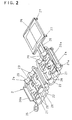
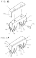
- Figs. 1 to 13 show an electric connector provided in an embodiment and adapted for use with two-wire VVF cables.
- Contacts 1 are made by pressing a conductive brass sheet harder than the cabies 3 and 3', and each of an inverted-U shape.
- Each contact 1 is composed of two parallel and thin unit pieces 1a, and two slits 11 formed in each piece are separated by a valley 12 to be spaced a distance 'D' from each other.
- Those slits 11 are shaped such that they will pierce an external insulating mantle 31 and an internal insulating jacket 32 so as to bite a conductor 33 covered therewith.
- Each side cutter 13 is disposed beside the respective slits 11, and each side cutter extends between and perpendicular to the parallel and thin unit pieces 1a and has its basal ends integral therewith. Those side cutters will pierce the mantle 31 at a portion thereof intermediate the jackets 32, so that the latter may be separated from each other.
- each slit 11 intervenes between a pair of V-shaped blades designed such that they will pierce and sever both the mantle 31 and the jackets 32, thereby allowing the slit to bite and grip the conductor 33 in the so-called 'insulation displacement' manner.
- the slits 11 are slanted with respect to two parallel, imaginarily vertical lines along which the contact will advance into the connector. Due to this feature, one of the conductors forced to fit in each slit will be repelled from the other conductor included in the same cable, as the contact is struck into the connector.
- each side cutter 13 consists of lower edges of ears 13a and 13a that protruding from and integral with the unit pieces 1a confronting one another.
- Each ear 13a is bent at right angle at its basal portion continuing to the piece 1a, so that ends of those ears protruding towards each other do abut against one another. Width in the vertical direction ( in the same sense as above ) of the ears 13a is rendered as small as possible, but not impermissibly lowering their strength.
- An idle space appearing above each ear 13a is filled with one of vertical tablets 14a made of a plastics.
- the side cutters 13 will be provided with a sufficient ability of piercing the insulating mantle and jackets on one hand, and satisfactory protection from electric shock will be ensured even if they would fail to make their correct way in between the neighboring conductors 30 in one cable.
- the outer vertical tablet 14a is formed integral with a horizontal plastics tablet 14 to assume an L-shape.
- three discrete tablets 14, 14a and 14a may be employed, or two vertical ones 14a of them may be dispensed with.
- each ear 13a is included in the same plane as the unit piece 1a, but protruding sideways therefrom such that a shoulder 15 facing downwards is defined between said ear's end and a lateral lower edge of the piece's portion located beside each slit.
- a pair of those shoulders 15 disposed at opposite ends of each side cutter 13. Since no blade is formed in the shoulder 15, it will push down a small mass of the mantle 31 (usually made of a polyvinyl chloride resin ) into a fine crevice present between the jackets 32 when the side cutter 13 intrudes the cable as illustrated in Figs. 9 and 10.
- Thickness of the parallel unit pieces of the contact 1 and width of each slit 11 formed therein may desirably be designed such that an area of each conductor's portions brought into 'insulation displacement' contact with the slit is equal to or larger than its cross-sectional area.
- the conductor's diameter is 1.6 mm, with the unit pieces of each contact 1 being 0.5 mm thick, then the slits 11 may be about 1.2 mm wide.
- the conductors have a diameter of 2.0 mm and the contact is 0.6 mm thick, then the slits 11 may be about 1.5 mm wide.
- the shoulders 15 may protrude a distance of 0.8 - 1.0 mm from the unit piece.
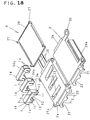
- the connector body 2 is an integral piece that may be formed of a Nylon ( registered trademark ), a polyethylene, a polypropylene or the like plastics.
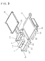
- a pair of halves 2a and 2b constitute together with a lid 26 the connector body 2, wherein two parallel split grooves 21 and 22 formed in each half are spaced a distance 'E' one from another.
- One of those complementary halves 2a has two slots 23 formed therein and continues at one lateral side transversely to a foldable ear 24 which in turn continues to the other half 2b.
- those halves can be superimposed one on another to complete the body, wherein they have at their other ends a perforated principal ear 20a and a lug 20b fitting therein, respectively.
- the lid 26 connected by flexible band 25 to one of the halves 2a and extending outwardly thereof in a direction of the grooves can be folded back onto said half 2a to cover its face through which the contacts are inserted.
- Hooks 27 protruding from the lid 26 are engageable with additional perforated ears 27a of one of the halves 2a.
- Eye-tabs 35 of the other half 2b are for use to suspend or fix this connector to a neighboring article.
- Width of each split groove 21 and 22 is substantially equal to width 'W(capital)' of each VVF cable 3 and 3' in a plane in which the conductors are arranged side by side in the VVF cable.
- the sum of depth of mating split grooves 21 or 22 is substantially the same as thickness 'w(minuscule)' of each cable. Therefore, those cables tightly fit in the respective completed grooves.
- Distance 'E' between the longitudinal axes of the two complete grooves 21 and 22 corresponds to that 'D' of the two slits 11.
- each slot 23 is of a shape similar to that of the contact 1 in plan view, so that the lower parts of the contacts remain in said slots unless and until any external force is applied to them.
- the slots 23 are disposed offset transversely and relative to one another, corresponding to distance by which two conductors 33 are spaced in each VVF cable.
- the contacts 1 and the slots 23 are of the same unsymmetrical shape, for example of the same elongate trapezoidal shape in plan view, for ensuring directivity in insertion of the former into the latter.
- the side cutters 13 can always cut into the VVF cables just in between the neighboring conductors 33, thus assuring correct branching works as shown in Figs. 9 and 11.
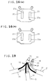
- the contacts may have along their peripheries some indentations 23a or protrusions as shown in Figs. 16(a) and 16(b), corresponding to protrusions or indentations of the contacts not shown.
- the foldable ear 24 is thin and W-shaped in side elevation so that the complementary halves 2a and 2b are easily folded onto each other, after the lower parts of the contacts 1 having fitted in the slots 23 so as to be temporarily held in place therein.
- Annular grooves 29 are formed in both ends of each groove 21 and 22 for selectively and removably receiving therein a blind plate or stopper 28.
- This blind plate intended to bear against a cut end of the branch VVF cable may be transparent for visual confirmation of said end.
- the blind plate 28 in the present embodiment is an integral piece, it may be split into halves fittable in respective halves of any such annular groove 29.
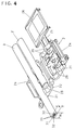
- the blind plate 28 will at first be set in the annular groove 29 that is formed in the straight groove 21 for accommodation of a branch cable 3'. Then the bus cable 3 will be placed in one of the complementary halves 2a or 2b ( '2b' in this example ) as shown in Fig. 4. Thereafter, the branch cable 3' will be set in the other groove 22, to take a correct position with respect to polarity of its conductors relying on previous and visual check of its cut end that subsequently has to abut against the blind plate 28.
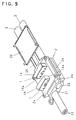
- the other half ( '2a' here ) of the connector body will be swung onto and fixed on the one of said halves, by bending the common ear 24 and engaging the hook 20b with the perforated ear 20a, to take a position shown in Fig. 5.
- the branch cable 3' may alternatively be inserted into such a closed body.
- a proper pressing tool will be used to strike and press the upper faces of contacts 1 one by one as shown in Fig. 6, so that each of them is fully embedded in the connector as shown in Fig. 7.
- the lid 26 is placed on the upper face of the connector by bending the bands 25 and engaging the corner hooks 27 with the perforated ears 27a as shown in Fig. 8, to thereby hide the contacts' exposed outer ends.
- each contact 1 takes a position within the connector body 2 as shown in Figs. 9 and 11.
- Each contact penetrating the mantles 31 of the cables 3 and 3' will also pierce the jackets 32 covering the respective conductors 32 of the same polarity.
- the side cutters 13 of the contact thus having come into electric contact with said conductors 33 of one polarity ( '+' or '-' ) will already have displaced them away from the other conductors 33 of the other polarity ( '-' or '+' ), a small distance within the connector.
- This effect is enhanced by the oblique slits 11 to thereby improve safety in respect of the branching an existing or bus cable.
- the eye-tabs 35 are useful to suspend the connector together with the cables 3 and 3' from any proper article or architectural part within a building.
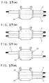
- One or more blind plates 28 may be set in any selected annular grooves 29 or may be dispensed with. In a case exemplified above, one blind plate is used in a manner shown in Fig. 17(a) to allow the branch 3' to protrude in only one way from the connector. Figs. 17(b) to 17(d) show other possibilities in location of the blind plates.
- Fig. 17(b) shows another manner of using the connector as a "relay connector", in which ends of two VVF cables 3 and 3 are put therein towards each other. Those cable ends in such a case are respectively stopped with the blind plates 28 fitted in the grooves 29 that are located at different sides of the connector.
- both the cable ends 3 are disposed on the same side of the connector, which likewise serves as a relay connector.
- the contacts 1 can naturally connect the connectors 33 of the same polarity.
- connectors for use with two-wire VVF cables have been described, they may be modified to comprise three contacts and three slots therefor in order to be connected to three-wire cables, without affecting all the other remaining features.
- the complementary halves 2a and 2b of the connector body may be quite separate parts engaging one another, with the common ear 24 being dispensed with.
- the contacts of an inverted-U shape can alternatively be made by processing a metal sheet previously coated with an insulating material.
- this sheet may not necessarily be a copper alloy sheet, but may be a sheet of any other metal or the like whose hardness is higher than the conductors of the VVF cables 3 and 3' and whose conductivity is high enough for use in the connector.
- the connector provided herein is constructed such that whose contacts can simply be pressed to electrically engage even with a live existing VVF cable, without necessity of the previous switching off of it.
- the peculiar configuration of each contact is effective to displace one of the conductors away from the other simultaneously with the driving of the contact into the connector, thereby enhancing safety of the wiring and the branching operation.
- the connector can be produced inexpensively.
Landscapes
- Multi-Conductor Connections (AREA)
- Connections By Means Of Piercing Elements, Nuts, Or Screws (AREA)
- Coupling Device And Connection With Printed Circuit (AREA)
Applications Claiming Priority (4)
| Application Number | Priority Date | Filing Date | Title |
|---|---|---|---|
| JP16623198 | 1998-05-28 | ||
| JP10166231A JP2913000B1 (ja) | 1998-05-28 | 1998-05-28 | コネクタ |
| JP10166232A JP2913001B1 (ja) | 1998-05-28 | 1998-05-28 | コネクタ |
| JP16623298 | 1998-05-28 |
Publications (3)
| Publication Number | Publication Date |
|---|---|
| EP0961348A2 true EP0961348A2 (de) | 1999-12-01 |
| EP0961348A3 EP0961348A3 (de) | 2000-05-10 |
| EP0961348B1 EP0961348B1 (de) | 2002-07-03 |
Family
ID=26490685
Family Applications (1)
| Application Number | Title | Priority Date | Filing Date |
|---|---|---|---|
| EP98307579A Expired - Lifetime EP0961348B1 (de) | 1998-05-28 | 1998-09-17 | Elektrischer Verbinder |
Country Status (2)
| Country | Link |
|---|---|
| EP (1) | EP0961348B1 (de) |
| DE (1) | DE69806344T2 (de) |
Cited By (2)
| Publication number | Priority date | Publication date | Assignee | Title |
|---|---|---|---|---|
| FR2858059A1 (fr) * | 2003-07-22 | 2005-01-28 | Mediterranee Const Ind | Module de raccordement pour chaine de securite |
| EP1621409A3 (de) * | 2004-07-27 | 2006-05-17 | Schmitz Gotha Fahrzeugwerke GmbH | Beleuchtungsanordnung eines Lastfahrzeugs, insbesondere eines Anhängers, sowie Kabelverbinder hierfür |
Families Citing this family (1)
| Publication number | Priority date | Publication date | Assignee | Title |
|---|---|---|---|---|
| CN103337718B (zh) * | 2013-06-08 | 2016-06-01 | 积架宝威汽车配件(深圳)有限公司 | 一种电子线刺破式连接器 |
Family Cites Families (4)
| Publication number | Priority date | Publication date | Assignee | Title |
|---|---|---|---|---|
| JP3113132B2 (ja) * | 1993-10-20 | 2000-11-27 | ミネソタ マイニング アンド マニュファクチャリング カンパニー | 接続子 |
| JP3636393B2 (ja) * | 1995-10-31 | 2005-04-06 | ミネソタ マイニング アンド マニュファクチャリング カンパニー | 分岐コネクタ装置 |
| JPH09289047A (ja) * | 1996-04-23 | 1997-11-04 | Nichifu Co Ltd | コネクター |
| JP2985060B2 (ja) * | 1996-10-15 | 1999-11-29 | 株式会社ニチフ端子工業 | コネクタ |
-
1998
- 1998-09-17 DE DE69806344T patent/DE69806344T2/de not_active Expired - Fee Related
- 1998-09-17 EP EP98307579A patent/EP0961348B1/de not_active Expired - Lifetime
Cited By (2)
| Publication number | Priority date | Publication date | Assignee | Title |
|---|---|---|---|---|
| FR2858059A1 (fr) * | 2003-07-22 | 2005-01-28 | Mediterranee Const Ind | Module de raccordement pour chaine de securite |
| EP1621409A3 (de) * | 2004-07-27 | 2006-05-17 | Schmitz Gotha Fahrzeugwerke GmbH | Beleuchtungsanordnung eines Lastfahrzeugs, insbesondere eines Anhängers, sowie Kabelverbinder hierfür |
Also Published As
| Publication number | Publication date |
|---|---|
| EP0961348A3 (de) | 2000-05-10 |
| EP0961348B1 (de) | 2002-07-03 |
| DE69806344T2 (de) | 2003-02-20 |
| DE69806344D1 (de) | 2002-08-08 |
Similar Documents
| Publication | Publication Date | Title |
|---|---|---|
| EP0653803B1 (de) | Elektrischer Schneidklemmverbinder mit verbesserter Zugentlastung | |
| CA1314082C (en) | Electrical connection device providing integral strain relief | |
| EP0063457B1 (de) | Elektrischer Kontakt und Zusammenbau eines elektrischen Verbinders | |
| IE911423A1 (en) | A cutting terminal contact | |
| JPH0760713B2 (ja) | ケーブルクランプ装置 | |
| JPH10228932A (ja) | 圧接端子の構造 | |
| CA2234654C (en) | Branch connector apparatus | |
| EP0654849B1 (de) | Elektrischer Abzweigverbinder | |
| CA2960155C (en) | Coupler connector and cable terminator with end contacts | |
| JPH11505664A (ja) | 電線接続システム | |
| CA1140227A (en) | Method of terminating shielded electrical cable and an assembly comprising an electrical connector terminating such cable | |
| US3805221A (en) | Inspectable-corrosion resistant electrical connector | |
| EP0961348B1 (de) | Elektrischer Verbinder | |
| US3835241A (en) | Adaptor for modifying connector to accommodate smaller conductors | |
| US5520549A (en) | Connector apparatus, housing, and connecting element | |
| JPH076800A (ja) | 機械的弛み止めを備えた圧着導線端子 | |
| EP0913895A2 (de) | Tragbare Presse für Schneidklemmverbinder | |
| JP2000058148A (ja) | 圧接端子 | |
| JP2001217014A (ja) | 圧接端子 | |
| JP3542712B2 (ja) | 圧接端子 | |
| JP4067297B2 (ja) | ピアシング端子接続構造 | |
| US7527518B1 (en) | Contact device for insulation displacement connector | |
| JPH11500576A (ja) | 多重極雌ストリップ・コネクタと接続するための方法 | |
| GB2210514A (en) | Terminating insulated conductors | |
| ATE215753T1 (de) | Vorrichtung zum umformen von leitungsummantelungen elektrischer leitungen und verfahren zum umformen von leitungsummantelungen mit hilfe einer solchen vorrichtung |
Legal Events
| Date | Code | Title | Description |
|---|---|---|---|
| PUAI | Public reference made under article 153(3) epc to a published international application that has entered the european phase |
Free format text: ORIGINAL CODE: 0009012 |
|
| AK | Designated contracting states |
Kind code of ref document: A2 Designated state(s): CH DE FR GB IT LI |
|
| AX | Request for extension of the european patent |
Free format text: AL;LT;LV;MK;RO;SI |
|
| PUAL | Search report despatched |
Free format text: ORIGINAL CODE: 0009013 |
|
| AK | Designated contracting states |
Kind code of ref document: A3 Designated state(s): AT BE CH CY DE DK ES FI FR GB GR IE IT LI LU MC NL PT SE |
|
| AX | Request for extension of the european patent |
Free format text: AL;LT;LV;MK;RO;SI |
|
| 17P | Request for examination filed |
Effective date: 20000502 |
|
| 17Q | First examination report despatched |
Effective date: 20000815 |
|
| AKX | Designation fees paid |
Free format text: CH DE FR GB IT LI |
|
| GRAG | Despatch of communication of intention to grant |
Free format text: ORIGINAL CODE: EPIDOS AGRA |
|
| GRAG | Despatch of communication of intention to grant |
Free format text: ORIGINAL CODE: EPIDOS AGRA |
|
| GRAH | Despatch of communication of intention to grant a patent |
Free format text: ORIGINAL CODE: EPIDOS IGRA |
|
| GRAH | Despatch of communication of intention to grant a patent |
Free format text: ORIGINAL CODE: EPIDOS IGRA |
|
| GRAH | Despatch of communication of intention to grant a patent |
Free format text: ORIGINAL CODE: EPIDOS IGRA |
|
| GRAH | Despatch of communication of intention to grant a patent |
Free format text: ORIGINAL CODE: EPIDOS IGRA |
|
| GRAH | Despatch of communication of intention to grant a patent |
Free format text: ORIGINAL CODE: EPIDOS IGRA |
|
| GRAA | (expected) grant |
Free format text: ORIGINAL CODE: 0009210 |
|
| AK | Designated contracting states |
Kind code of ref document: B1 Designated state(s): CH DE FR GB IT LI |
|
| PG25 | Lapsed in a contracting state [announced via postgrant information from national office to epo] |
Ref country code: LI Free format text: LAPSE BECAUSE OF FAILURE TO SUBMIT A TRANSLATION OF THE DESCRIPTION OR TO PAY THE FEE WITHIN THE PRESCRIBED TIME-LIMIT Effective date: 20020703 Ref country code: IT Free format text: LAPSE BECAUSE OF FAILURE TO SUBMIT A TRANSLATION OF THE DESCRIPTION OR TO PAY THE FEE WITHIN THE PRESCRIBED TIME-LIMIT;WARNING: LAPSES OF ITALIAN PATENTS WITH EFFECTIVE DATE BEFORE 2007 MAY HAVE OCCURRED AT ANY TIME BEFORE 2007. THE CORRECT EFFECTIVE DATE MAY BE DIFFERENT FROM THE ONE RECORDED. Effective date: 20020703 Ref country code: CH Free format text: LAPSE BECAUSE OF FAILURE TO SUBMIT A TRANSLATION OF THE DESCRIPTION OR TO PAY THE FEE WITHIN THE PRESCRIBED TIME-LIMIT Effective date: 20020703 |
|
| REG | Reference to a national code |
Ref country code: CH Ref legal event code: EP |
|
| REF | Corresponds to: |
Ref document number: 69806344 Country of ref document: DE Date of ref document: 20020808 |
|
| ET | Fr: translation filed | ||
| REG | Reference to a national code |
Ref country code: CH Ref legal event code: PL |
|
| PLBE | No opposition filed within time limit |
Free format text: ORIGINAL CODE: 0009261 |
|
| STAA | Information on the status of an ep patent application or granted ep patent |
Free format text: STATUS: NO OPPOSITION FILED WITHIN TIME LIMIT |
|
| 26N | No opposition filed |
Effective date: 20030404 |
|
| PGFP | Annual fee paid to national office [announced via postgrant information from national office to epo] |
Ref country code: FR Payment date: 20050823 Year of fee payment: 8 |
|
| PGFP | Annual fee paid to national office [announced via postgrant information from national office to epo] |
Ref country code: GB Payment date: 20050914 Year of fee payment: 8 |
|
| PGFP | Annual fee paid to national office [announced via postgrant information from national office to epo] |
Ref country code: DE Payment date: 20050915 Year of fee payment: 8 |
|
| PG25 | Lapsed in a contracting state [announced via postgrant information from national office to epo] |
Ref country code: DE Free format text: LAPSE BECAUSE OF NON-PAYMENT OF DUE FEES Effective date: 20070403 |
|
| GBPC | Gb: european patent ceased through non-payment of renewal fee |
Effective date: 20060917 |
|
| REG | Reference to a national code |
Ref country code: FR Ref legal event code: ST Effective date: 20070531 |
|
| PG25 | Lapsed in a contracting state [announced via postgrant information from national office to epo] |
Ref country code: GB Free format text: LAPSE BECAUSE OF NON-PAYMENT OF DUE FEES Effective date: 20060917 |
|
| PG25 | Lapsed in a contracting state [announced via postgrant information from national office to epo] |
Ref country code: FR Free format text: LAPSE BECAUSE OF NON-PAYMENT OF DUE FEES Effective date: 20061002 |