EP0961220A2 - Digitale Druckerschnittstelle - Google Patents
Digitale Druckerschnittstelle Download PDFInfo
- Publication number
- EP0961220A2 EP0961220A2 EP99104480A EP99104480A EP0961220A2 EP 0961220 A2 EP0961220 A2 EP 0961220A2 EP 99104480 A EP99104480 A EP 99104480A EP 99104480 A EP99104480 A EP 99104480A EP 0961220 A2 EP0961220 A2 EP 0961220A2
- Authority
- EP
- European Patent Office
- Prior art keywords
- interface
- printer
- interface card
- line
- card
- Prior art date
- Legal status (The legal status is an assumption and is not a legal conclusion. Google has not performed a legal analysis and makes no representation as to the accuracy of the status listed.)
- Withdrawn
Links
Images


Classifications
-
- G—PHYSICS
- G06—COMPUTING; CALCULATING OR COUNTING
- G06K—GRAPHICAL DATA READING; PRESENTATION OF DATA; RECORD CARRIERS; HANDLING RECORD CARRIERS
- G06K15/00—Arrangements for producing a permanent visual presentation of the output data, e.g. computer output printers
-
- G—PHYSICS
- G06—COMPUTING; CALCULATING OR COUNTING
- G06K—GRAPHICAL DATA READING; PRESENTATION OF DATA; RECORD CARRIERS; HANDLING RECORD CARRIERS
- G06K2215/00—Arrangements for producing a permanent visual presentation of the output data
- G06K2215/0002—Handling the output data
- G06K2215/0005—Accepting output data; Preparing data for the controlling system
Definitions
- DFE digital front end
- a computer usually has a backplane which provides a standard interface between cards, and a peripheral such as a disk drive may be sold with an interface card that communicates between the drive and the backplane.
- the backplane is the interface.
- a different configuration is used in a modem networked printer.
- the generation of a page containing text and image data frequently starts at a terminal where the user generates a computer generated graphic or receives a contone image from a scanner, generates text, combines image and text in a highly compressed form using a page description language (PDL), and sends the result to a printer server, a DFE, which is usually located somewhere near the printer.
- a decomposer expands the PDL into separations of bit maps and sends the resultant video over wire or fiber cables or a network to the printer.
- the printer has an interface card which reformats the data into rasters, halftones them in a rendering card, and applies them to the raster output scanner (ROS), In this case, the interface is the connection between the server and the printer.
- ROS raster output scanner
- This invention provides for the interface to be between an interface card and the rendering card. Both are within the printer, but the interface is now separate from the backplane. Also, the server manufacturer, who designed the transmitter for the means of communication between the server and printer, also designs the receiver. This is a much more efficient method of designing a networked printing system since the server manufacturer who already has the expertise in designing, for example, a fiber optic network transmitter can conveniently design the receiver as well, allowing the printer designer to concentrate on the design of the printing mechanism. In this case, the printer designer specifies the interface signals, such as the number of data lines, and the ancillary clock, reset, error, page and line signals, and the server manufacturer designs the interface card to produce these signals from its own server output. The result is an interface card which plugs into the backplane of the printer, and has a connection, of any type, to the server.
- the interface being described here is a high speed image data path, and exists in addition to a more usual connection, such as a local area network, over which the print engine and DFE can communicate. For example, negotiations between the front end and the print engine are handled over the network connection.
- Fig 1 is an overall block diagram of the system.
- the digital front end 10 decomposes page description language and sends a number of separations of byte maps of contone video to the interface cards 12 by any means at the convenience of the DFE manufacturer.
- the separations are assumed to be cyan, magenta, yellow, black and one other, as shown.
- the interface 15 is between each interface card 12 and its corresponding rendering card 13. That output is then applied to the printer backplane or bus 14 for application to the print engine controller 16.
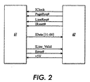
- the 60 line interface in this described embodiment has 32 data lines, one each reset, clock, error, line valid, line request and page request lines and several power and ground lines.
- the data, line valid, and error signals go from the interface card 61 to the rendering card 62 while the remainder go from the rendering card to the interface card.
- the page request signal is driven active by the rendering card to indicate the start of a new page of data.
- the line request signal is driven active by the rendering card to indicate that data transfer should commence.
- the interface card must drive image data onto the data lines and drive line valid, On the next clock edge the rendering card will latch the image data on the data lines.
- the interface card must drive a new set of image data onto the data lines every clock cycle until the entire line of data has been transferred.
- the interface card will stop driving new data out on the bus when all of the data for an entire line has been transferred.
- the interface card will also deactivate line valid.
- the rendering card deactivates the line request.
- the next scan line of image data is transferred when the line request again goes active, This process repeats until all of the scanlines for the image have been transferred. All image data transfers must be multiples of four pixels.
- the rendering card will deactivate the page request signal.
- the interface card must then check that exactly the correct amount of image data was transferred. If there was image data left over, or if there was not enough image data, then the interface asserts the error signal. The interface card will also assert the error signal if it detects any kind of problem during the transfer of the image data. It is the responsibility of the print engine controller to perform recovery and reset the error signal.
- the image data interface signals are described with respect to the following spatial imaging conventions, which must be followed by the front end and print engine.
- the interface-supplied image is a rectangular image space whose sides are parallel to the slow scan and fast scan directions of the print engine.
- Fig 3 shows the generalized relationships when viewing the imaged side of the paper.
- the first pixel delivered to the image is located at the lower left hand corner, as viewed from the start-of-scan edge.
- the fast and slow scan proceed upward and to the right, respectively.
- Active image data is the image information that is intended to appear on the paper. It is the responsibility of the front end to align the page image data within the interface supplied frame so that it is imaged on the paper.
- the interface card must supply data for these margins.
- the start-of-page margin is created by sending background data (no ink) for the first m scan lines.
- the end-of-page margin is created by sending background data for the last n scan lines of the page.
- the start-of-scan margin is created by sending background data for the first s pixels in the scan line.
- the end-of-scan margin is created by sending background data for the last t pixels in the scan line.
- the values of m, n, s and t are negotiated by the front end and the printing engine.
- the print engine is responsible for providing any margins necessary to cover the print engine registration tolerance.
- the front end is responsible for providing all other margins.
- the margins must be white (no ink), The front end will negotiate the margins and paper registration location.
- the image clock is generated by the rendering card and sent to the interface card. It is a free-running clock. Both the sender and receiver use this clock to synchronize all signals. All signals are sampled on the rising edge of the clock.
- the page request signal is generated in the rendering card and sent to the interface card. It defines each slow scan imaging interval to the interface card in real time. Its primary purpose is to synchronize the delivery of an image frame worth of video data to the rendering card.
- the interface card must deliver a page worth of video data for each page request received, The duration of page request defines the page size in the slow scan direction. The beginning of the page request must correspond to the leading edge of the paper, and the end of page request must correspond to the trailing edge of the page.
- the interface card must be capable of delivering scan lines containing page image data starting with the second line request following the beginning of each page request.
- the line request is generated in the rendering card and sent to the interface card. It defines each fast scan imaging interval to the interface card in real time. It synchronizes the delivery of a scan line worth of video data to the rendering card.
- Line request going active marks the nominal start of the largest image size in the fast scan direction. Line request is a free-running signal and occurs even when page request is inactive.
- the line valid is generated in the interface card and sent to the rendering card to indicate that the data on the data lines is valid. This signal must be activated within a specified number of clocks following the receipt of the line request signal. The line valid remains activated until an entire line of data has been transferred.
- the error signal is generated in the interface card and sent to the rendering card to indicate an error condition.
- the interface card shall assert the error signal no later than 256 clocks upon detecting the error condition. It is the responsibility of the print engine to take appropriate action.
- the possible errors are described as follows:
- the reset signal is generated by the rendering card to reset the interface card.
- the typical use of this signal is to reset the error signal generated by the interface card and to put the interface card into a known state. To properly reset the error signal and internal logic on the interface card, the reset signal needs to be active for a minimum of 20 clocks.
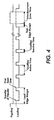
- Fig 4 shows the page request and line request timing relationship. The following section describes the terms used in the figure.
- the lead edge margin time is the time between page request going active for the second time.
- the length of the lead edge margin varies depending on certain factors.
- the interface card does not transfer image data during the lead edge margin time.
- the Line Valid active time controls the number of pixels transferred across the interface in the fast scan direction.
- the interface card drives margin and image data across the interface to put marks on paper in the line valid active time.
- the Line Valid active time in terms of the number of pixels, is negotiated between the DFE and the Print Engine before the start of the page.
- the length of the line request inactive time varies depending on print engine factors.
- the interface card does not transfer image data during this time.
- the trail edge margin time is the time between the last line request going inactive and page request going inactive.
- the interface card does not transfer image data during this time.
- the interpage gap time is the time that page request is inactive.
- the interface card does not transfer image data during this time.
- the intergap time varies depending on print engine factors.
- This header field consists of 8 bytes of data that is used to indicate the image number. The rest of the line is filled with zeros.
- the print engine uses this header to keep track of the page images so that the pages will be printed in the correct order for one-sided or two-sided operation.
- the header is also used to test the integrity of the system.
- the header information is passed to the print controller by the renderer. The header data is not printed.
- the header field is sent from the front end to the renderer at the beginning of each image. After page request goes active, the first line request is used to transfer the header data.
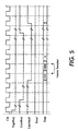
- Fig 5 shows the first line request and header data transfer timing. The header field is always present.
- the interface card Upon detecting page request and line request active after transfer of the header, the interface card drives the image data across the interface. The interface card continues to drive image data every clock until the entire line is sent.
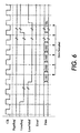
- the image data is arranged in the 32-bit word such that the lowest numbered pixel is in bits 31:24 and the highest numbered pixel is in bits 7:0 of the data.
- the least significant bit of each pixel is in the lower numbered bit (24, 16, 8, 0) of the byte, and the most significant bit of each pixel is in the higher numbered bit (31, 23, 15, 7) of the byte.
- the image data pixel value of 0 corresponds to no ink
- the image data pixel value of 255 corresponds to full (saturated) ink.
- the image data pixel values between 0 and 255 correspond to partial ink with the amount of saturation increasing as the value increases.
- Fig 6 shows the data transfer timing and Fig 7 shows the interface pin assignments.
Applications Claiming Priority (2)
| Application Number | Priority Date | Filing Date | Title |
|---|---|---|---|
| US09/087,818 US6064492A (en) | 1998-05-29 | 1998-05-29 | Image data interface between digital front end and printer |
| US87818 | 1998-05-29 |
Publications (2)
| Publication Number | Publication Date |
|---|---|
| EP0961220A2 true EP0961220A2 (de) | 1999-12-01 |
| EP0961220A3 EP0961220A3 (de) | 2004-01-02 |
Family
ID=22207440
Family Applications (1)
| Application Number | Title | Priority Date | Filing Date |
|---|---|---|---|
| EP99104480A Withdrawn EP0961220A3 (de) | 1998-05-29 | 1999-03-05 | Digitale Druckerschnittstelle |
Country Status (3)
| Country | Link |
|---|---|
| US (1) | US6064492A (de) |
| EP (1) | EP0961220A3 (de) |
| JP (1) | JP2000047837A (de) |
Cited By (1)
| Publication number | Priority date | Publication date | Assignee | Title |
|---|---|---|---|---|
| CN104245334A (zh) * | 2012-02-09 | 2014-12-24 | 勃来迪环球股份有限公司 | 使用对象识别的标签创建的系统和方法 |
Families Citing this family (18)
| Publication number | Priority date | Publication date | Assignee | Title |
|---|---|---|---|---|
| GB9603582D0 (en) | 1996-02-20 | 1996-04-17 | Hewlett Packard Co | Method of accessing service resource items that are for use in a telecommunications system |
| US6786420B1 (en) | 1997-07-15 | 2004-09-07 | Silverbrook Research Pty. Ltd. | Data distribution mechanism in the form of ink dots on cards |
| US6618117B2 (en) | 1997-07-12 | 2003-09-09 | Silverbrook Research Pty Ltd | Image sensing apparatus including a microcontroller |
| US6690419B1 (en) | 1997-07-15 | 2004-02-10 | Silverbrook Research Pty Ltd | Utilising eye detection methods for image processing in a digital image camera |
| US7110024B1 (en) | 1997-07-15 | 2006-09-19 | Silverbrook Research Pty Ltd | Digital camera system having motion deblurring means |
| US6879341B1 (en) | 1997-07-15 | 2005-04-12 | Silverbrook Research Pty Ltd | Digital camera system containing a VLIW vector processor |
| US6624848B1 (en) | 1997-07-15 | 2003-09-23 | Silverbrook Research Pty Ltd | Cascading image modification using multiple digital cameras incorporating image processing |
| US6948794B2 (en) | 1997-07-15 | 2005-09-27 | Silverbrook Reserach Pty Ltd | Printhead re-capping assembly for a print and demand digital camera system |
| JP3767163B2 (ja) * | 1998-03-26 | 2006-04-19 | コニカミノルタビジネステクノロジーズ株式会社 | 画像形成装置の制御方法及び画像形成装置 |
| AUPP702098A0 (en) | 1998-11-09 | 1998-12-03 | Silverbrook Research Pty Ltd | Image creation method and apparatus (ART73) |
| US7236271B2 (en) * | 1998-11-09 | 2007-06-26 | Silverbrook Research Pty Ltd | Mobile telecommunication device with printhead and media drive |
| AUPP702198A0 (en) * | 1998-11-09 | 1998-12-03 | Silverbrook Research Pty Ltd | Image creation method and apparatus (ART79) |
| US6295538B1 (en) * | 1998-12-03 | 2001-09-25 | International Business Machines Corporation | Method and apparatus for creating metadata streams with embedded device information |
| AUPQ056099A0 (en) | 1999-05-25 | 1999-06-17 | Silverbrook Research Pty Ltd | A method and apparatus (pprint01) |
| US6718878B2 (en) * | 1999-09-29 | 2004-04-13 | Xerox Corporation | Automatic detection of black and white pages in a color document stream |
| US7636177B2 (en) * | 2004-04-23 | 2009-12-22 | Xerox Corporation | Systems and methods for forming composite images with digital graphic elements |
| US8238538B2 (en) | 2009-05-28 | 2012-08-07 | Comcast Cable Communications, Llc | Stateful home phone service |
| US8467092B2 (en) | 2010-01-21 | 2013-06-18 | Xerox Corporation | Method and system for creating and using customized sample rendering job |
Citations (3)
| Publication number | Priority date | Publication date | Assignee | Title |
|---|---|---|---|---|
| US5440410A (en) * | 1990-09-27 | 1995-08-08 | Canon Kabushiki Kaisha | Control system for transmitting and recording image data in accordance with a predetermined recording width or type of recording medium |
| US5687303A (en) * | 1994-05-18 | 1997-11-11 | Xerox Corporation | Printer controller for object optimized printing |
| US5706410A (en) * | 1995-09-25 | 1998-01-06 | Hewlett-Packard Company | Printing system having control language command and raster pixel image data processing capability |
Family Cites Families (12)
| Publication number | Priority date | Publication date | Assignee | Title |
|---|---|---|---|---|
| EP0486312B1 (de) * | 1990-11-16 | 1997-04-23 | Canon Kabushiki Kaisha | Bildschnittstellenanordnung |
| US5185853A (en) * | 1991-01-03 | 1993-02-09 | Acer Incorporated | Expandable printer buffer system |
| CA2075774C (en) * | 1991-08-27 | 2000-10-17 | Jeff D. Pipkins | Bidirectional parallel protocol |
| JPH06295285A (ja) * | 1993-02-15 | 1994-10-21 | Tokyo Electric Co Ltd | インターフェース装置及びこのインターフェース装置を使用したプリンタ |
| JP2587909B2 (ja) * | 1994-08-30 | 1997-03-05 | 株式会社アプティ | データ転送方法 |
| KR970010377B1 (ko) * | 1994-11-09 | 1997-06-25 | 삼성전자 주식회사 | 전자 사진 현상 방식 프린터의 인터페이싱 방법 |
| US5909539A (en) * | 1995-09-20 | 1999-06-01 | Casio Computer Co., Ltd. | Image generating system and method |
| US5754746A (en) * | 1995-12-18 | 1998-05-19 | Xerox Corporation | Multi bit per pixel compression/decompression using parallel encoded streams |
| US5884014A (en) * | 1996-05-23 | 1999-03-16 | Xerox Corporation | Fontless structured document image representations for efficient rendering |
| US5946459A (en) * | 1997-09-29 | 1999-08-31 | Xerox Corporation | System for clearing an image data buffer in a high-speed digital printing apparatus |
| US5970220A (en) * | 1997-10-15 | 1999-10-19 | Lexmark International, Inc. | Printer having universal image port and related system and method |
| US5978560A (en) * | 1997-11-07 | 1999-11-02 | Xerox Corporation | Load balancing of distributed printing systems using enhanced printer attributes |
-
1998
- 1998-05-29 US US09/087,818 patent/US6064492A/en not_active Expired - Lifetime
-
1999
- 1999-03-05 EP EP99104480A patent/EP0961220A3/de not_active Withdrawn
- 1999-05-21 JP JP11142425A patent/JP2000047837A/ja not_active Withdrawn
Patent Citations (3)
| Publication number | Priority date | Publication date | Assignee | Title |
|---|---|---|---|---|
| US5440410A (en) * | 1990-09-27 | 1995-08-08 | Canon Kabushiki Kaisha | Control system for transmitting and recording image data in accordance with a predetermined recording width or type of recording medium |
| US5687303A (en) * | 1994-05-18 | 1997-11-11 | Xerox Corporation | Printer controller for object optimized printing |
| US5706410A (en) * | 1995-09-25 | 1998-01-06 | Hewlett-Packard Company | Printing system having control language command and raster pixel image data processing capability |
Cited By (3)
| Publication number | Priority date | Publication date | Assignee | Title |
|---|---|---|---|---|
| CN104245334A (zh) * | 2012-02-09 | 2014-12-24 | 勃来迪环球股份有限公司 | 使用对象识别的标签创建的系统和方法 |
| CN104245334B (zh) * | 2012-02-09 | 2017-03-15 | 勃来迪环球股份有限公司 | 使用对象识别的标签创建的系统和方法 |
| US9800744B2 (en) | 2012-02-09 | 2017-10-24 | Brady Worldwide, Inc. | Systems and methods for label creation using object recognition |
Also Published As
| Publication number | Publication date |
|---|---|
| EP0961220A3 (de) | 2004-01-02 |
| US6064492A (en) | 2000-05-16 |
| JP2000047837A (ja) | 2000-02-18 |
Similar Documents
| Publication | Publication Date | Title |
|---|---|---|
| US6064492A (en) | Image data interface between digital front end and printer | |
| US20110157648A1 (en) | Data Pump For Printing | |
| US7722147B2 (en) | Printing system architecture | |
| US6538762B1 (en) | Printer controller, and print system | |
| US7003585B2 (en) | High speed serial interface | |
| US7667860B2 (en) | Control arrangement for a printing system | |
| EP1217576B1 (de) | Verfahren und Vorrichtung zum Formatieren und Bereitstellen von Bilddaten für Tintenstrahldrucker | |
| JPS59100663A (ja) | 多目的フアクシミリ装置 | |
| US7305490B2 (en) | Preparing electronic data for transmission | |
| US7106463B1 (en) | Controlling packet length for transfer between devices | |
| EP0673156A2 (de) | Farbbildverarbeitung | |
| JP3210029B2 (ja) | 画像処理装置及びその方法 | |
| US6721070B1 (en) | Apparatus and method for counting pixels in print data | |
| JP4366926B2 (ja) | プリントコントローラおよび画像処理プログラム | |
| KR19980021884A (ko) | 래스터 이미지를 고화질로 인쇄하는 프린터 및 방법 | |
| JP5057548B2 (ja) | 画像データ転送装置及び画像データ転送方法 | |
| US6731403B1 (en) | Color image process system, color image apparatus, color image processing method | |
| JPH11165450A (ja) | 印刷制御装置 | |
| WO1992005508A1 (en) | Equipment for controlling picture | |
| US6609864B1 (en) | Method and system for minimizing the memory requirements of a color image printing device | |
| JP3224612B2 (ja) | 同期信号伝送方式 | |
| JPH06130925A (ja) | 制御信号伝送方式 | |
| JP2008262471A (ja) | 画像出力装置 | |
| JP3427938B2 (ja) | 画像形成装置 | |
| US8699055B2 (en) | Image processing apparatus with symmetric processors |
Legal Events
| Date | Code | Title | Description |
|---|---|---|---|
| PUAI | Public reference made under article 153(3) epc to a published international application that has entered the european phase |
Free format text: ORIGINAL CODE: 0009012 |
|
| AK | Designated contracting states |
Kind code of ref document: A2 Designated state(s): AT BE CH CY DE DK ES FI FR GB GR IE IT LI LU MC NL PT SE |
|
| AX | Request for extension of the european patent |
Free format text: AL;LT;LV;MK;RO;SI |
|
| PUAL | Search report despatched |
Free format text: ORIGINAL CODE: 0009013 |
|
| AK | Designated contracting states |
Kind code of ref document: A3 Designated state(s): AT BE CH CY DE DK ES FI FR GB GR IE IT LI LU MC NL PT SE |
|
| AX | Request for extension of the european patent |
Extension state: AL LT LV MK RO SI |
|
| 17P | Request for examination filed |
Effective date: 20040702 |
|
| AKX | Designation fees paid |
Designated state(s): DE FR GB |
|
| 17Q | First examination report despatched |
Effective date: 20080620 |
|
| STAA | Information on the status of an ep patent application or granted ep patent |
Free format text: STATUS: THE APPLICATION IS DEEMED TO BE WITHDRAWN |
|
| 18D | Application deemed to be withdrawn |
Effective date: 20081001 |