EP0960409B1 - Verfahren zur uebertragung von daten in pulspausen eines drehzahlsignals und schaltungsanordnung zur durchfuehrung des verfahrens - Google Patents
Verfahren zur uebertragung von daten in pulspausen eines drehzahlsignals und schaltungsanordnung zur durchfuehrung des verfahrens Download PDFInfo
- Publication number
- EP0960409B1 EP0960409B1 EP98905358A EP98905358A EP0960409B1 EP 0960409 B1 EP0960409 B1 EP 0960409B1 EP 98905358 A EP98905358 A EP 98905358A EP 98905358 A EP98905358 A EP 98905358A EP 0960409 B1 EP0960409 B1 EP 0960409B1
- Authority
- EP
- European Patent Office
- Prior art keywords
- data
- signal
- pulse
- pulse pause
- speed signal
- Prior art date
- Legal status (The legal status is an assumption and is not a legal conclusion. Google has not performed a legal analysis and makes no representation as to the accuracy of the status listed.)
- Expired - Lifetime
Links
- 238000000034 method Methods 0.000 title claims description 17
- 230000005540 biological transmission Effects 0.000 claims description 35
- 230000001133 acceleration Effects 0.000 claims description 12
- 238000012546 transfer Methods 0.000 description 12
- 238000011156 evaluation Methods 0.000 description 5
- 230000015654 memory Effects 0.000 description 4
- 238000010586 diagram Methods 0.000 description 3
- 230000006978 adaptation Effects 0.000 description 2
- 230000002123 temporal effect Effects 0.000 description 2
- 230000006399 behavior Effects 0.000 description 1
- 230000001934 delay Effects 0.000 description 1
- 230000006870 function Effects 0.000 description 1
- 238000005259 measurement Methods 0.000 description 1
- 230000010363 phase shift Effects 0.000 description 1
- 238000012545 processing Methods 0.000 description 1
- 230000005855 radiation Effects 0.000 description 1
- 230000000630 rising effect Effects 0.000 description 1
- 230000008054 signal transmission Effects 0.000 description 1
- 230000001960 triggered effect Effects 0.000 description 1
Images

Classifications
-
- B—PERFORMING OPERATIONS; TRANSPORTING
- B60—VEHICLES IN GENERAL
- B60R—VEHICLES, VEHICLE FITTINGS, OR VEHICLE PARTS, NOT OTHERWISE PROVIDED FOR
- B60R16/00—Electric or fluid circuits specially adapted for vehicles and not otherwise provided for; Arrangement of elements of electric or fluid circuits specially adapted for vehicles and not otherwise provided for
- B60R16/02—Electric or fluid circuits specially adapted for vehicles and not otherwise provided for; Arrangement of elements of electric or fluid circuits specially adapted for vehicles and not otherwise provided for electric constitutive elements
- B60R16/03—Electric or fluid circuits specially adapted for vehicles and not otherwise provided for; Arrangement of elements of electric or fluid circuits specially adapted for vehicles and not otherwise provided for electric constitutive elements for supply of electrical power to vehicle subsystems or for
- B60R16/0315—Electric or fluid circuits specially adapted for vehicles and not otherwise provided for; Arrangement of elements of electric or fluid circuits specially adapted for vehicles and not otherwise provided for electric constitutive elements for supply of electrical power to vehicle subsystems or for using multiplexing techniques
-
- H—ELECTRICITY
- H04—ELECTRIC COMMUNICATION TECHNIQUE
- H04L—TRANSMISSION OF DIGITAL INFORMATION, e.g. TELEGRAPHIC COMMUNICATION
- H04L5/00—Arrangements affording multiple use of the transmission path
Definitions
- the invention relates to a method for the transmission of Data in pulse pauses of a speed signal, the maximum Number of transferable data determined from the time period is required for the transmission of information as well as from a time that is the length of the pulse pause corresponds.
- the invention also relates to a circuit arrangement for Execution of the procedure.
- the number of transferable uses data based on the duration of the transfer a single piece of information and the information available standing time in a pulse pause. Here is the to determine the maximum number of transferable data so that with a duration of the pulse pause, that of the maximum speed of the vehicle corresponds to the transmission of the data is completed before the next signal pulse of the speed signal occurs.
- this object is achieved by the maximum Adapted the number of data that can be transmitted in a pulse pause by, as a time that corresponds to the length of the pulse pause, a value is set which is at least a pulse pause just measured taking into account of a maximum value of the wheel acceleration.
- the number of data that can be transmitted during a pulse pause is adjusted depending on the driving speed. This makes it possible, for example; in the area lower Speed of the vehicle a larger number of Transfer data. The interpretation of the protocol regarding the number of transferable data is therefore only subject to less restrictions.
- the maximum number the data transmitted in a pulse pause are adapted so that data transmission is complete when the next signal pulse of the speed signal occurs.
- a protocol of the transferring data created, with an adaptation of the maximum Number of dates is done by single or multiple Data are omitted from the log, and being too a minimum duration for every possible number of data to be transmitted determined at least one previous pulse pause to be able to transfer this amount of data, and wherein based on the determined duration of the at least a previous pulse pause is determined how many Maximum data can be transferred.
- Data transmission is advantageous in the method aborted by a signal pulse of the speed signal if the duration of the data transmission is so long that already the next signal pulse of the speed signal is present.
- Advantageous is taken into account when evaluating the speed signal, whether the when the signal pulse of the Speed signal interrupted information the value "0" or Had "1".
- a circuit arrangement according to claim 5 is used for measurement the at least one pulse pause a counter a signal an oscillator and another signal is fed the further signal being the occurrence of a signal pulse represents the speed signal.
- this makes it easy to determine the length of the pulse pause become.
- this pulse pause and The table can easily determine how much data is safe can be transferred.
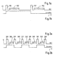
- Figure 1 shows a representation of the signal level at a Data transmission in pulse pauses.
- FIG. 1 a is the signal level of the signal pulse of the speed signal 101 higher than the signal level during data transmission 102. This allows the signal pulse of the speed signal from Signal pulses of data transmission are distinguished, so that there is no interference in the transmission of the speed may come because of the transfer of other data.
- Figure 1 b shows the associated waveform of the encoder that the Signal level every time on a rising edge of the signal pulse of the speed signal changes. In the shown Embodiment are in the pause between two signal pulses 101 of the speed signal data in the data bits with the numbers 0 to 5.
- Figure 2 shows the transmission of signal pulses of a speed signal 201, being in the breaks between signal pulses 201 data 202 are in turn transmitted.
- Figure 2a can be seen, the transfer of data is already done canceled at the data bit with the number 2. This is because because of the high vehicle speed, the temporal Sequence of the signal pulses 201 of the speed signal so is tight that for the complete transmission of all data bits there is not enough time.
- Figure 3 shows a representation of the time course with which the threshold value of the signal pulse of the speed signal is detected becomes.
- the representation of the curves with the vertical flanks concerns the signal level from top to bottom in data transmission (current source I1), the signal level of the speed signal (current source I2 in addition to Current source I1) and the resulting combined signal level (Isensor).
- Figure 3a shows the conditions when a signal pulse of the speed signal during data transmission, the signal level is at "1".
- Fig. 3b shows the conditions when at a signal pulse of the speed signal during data transmission the signal level is at "0".
- the encoder signal level changes when the signal level of the sensor exceeds the threshold. This can only happen if there is a signal pulse of the speed signal is present, that is, if both power sources are switched on.
- the signal levels are changed but not vertically but with a certain rise time.
- the time from the start of a change in signal level of the speed signal until the threshold value is exceeded depends on the "start value" of the signal level of the Speed signals. This leads to a dependency whether the signal level during data transmission data transfer when data transfer is aborted, i.e. at the beginning of the signal pulse of the speed signal, even was at "0" (as shown in FIG. 3a) or at "1" (as shown in Figure 3b).
- FIG. 3c show the relationships of Figure 3b. There the value of the current Isensor rises from 0, which is why the rise time until it is exceeded the threshold value is correspondingly larger.
- the signal level of the data transmission at "0" or "1" can also be used to estimate how many Data is transferable.
- This maximum number of data can are determined from the vehicle speed, i.e. the previous distance between two signal pulses of the speed signal and a maximum value of the acceleration. It then only as much data is transferred as is securely in the Pulse pause between the signal pulses of the speed signal can be transferred. This is at least largely ensures that the signal level at a signal pulse of the Speed signals not due to data transmission at "1" lies.
- n serves as the basis for assessment for a pulse pause hence the pulse pause (n-2).
- n-2 shows the length the pulse pause n as a function of the pulse pause (n-1) shown.
- the length of the current time window n corresponds to constant speed about the length of a previous one Time window n-1. Now finds a wheel acceleration instead, the width of the time window is shortened an amount corresponding to the acceleration value. Because of this Acceleration value is not predictable, the maximum possible acceleration value can be used to Even the worst case can still be recorded safely. This The maximum possible acceleration value can be based on plausibility considerations be determined. Usually is this maximum acceleration value is independent of the speed.
- T_1 1 / ((1 / (T_0 * K_vF) + a_max * T_0) * K_vF)
- T_1 T_0 / (1 + a_max * T_02 * K_vF)
- T T_0 * (1 / (1 + a_max * T_02 * K_vF) -1)
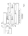
- FIG. 4 shows a basic illustration of a circuit arrangement, by means of the maximum number of securely transferable Data can be determined.
- the length of the time interval t_ (n-1) is generated using an oscillator and a frequency counter certainly. It can then have a specific count of the frequency counter a certain maximum number of Assign data that can be transmitted securely.
- the penultimate interval length to the maximum number of transferable Data closed.
- the signal 301 of an oscillator and a signal 302 that represents the occurrence of a signal pulse of the speed signal is fed to a counter 303.
- the binary The count of the counter 303 is alternately in one of the two Binary memories 304 and 305 loaded.
- With the control device 306 become the loading signals 307 and 308 for the two Binary memories 304 and 305 are generated so that the correct one Time of the count in the correct binary memory 304 and 305 is updated.
- the Controller 306 a signal 309, which is sent through the multiplexer 310 causes 304 or 305 to be in binary memory Data are passed to the decoder 311. in the Decoder 311 itself then becomes the binary value according to the information above, the maximum number of transferable Data determined.
- a certain minimum binary value of the Word corresponds to the release of a certain number of Data.
- the signals B1 --- B8 are correspondingly set to "1" set if the transmission of the respective data bit allows is.
- the signals B1 ... B8 in the shift register cause that only those data bits are loaded to "1" for which data transmission is permitted.
- the sensor signal evaluation must also be a special one Device included to the omitted data bits misinterpreted as set to "0". The same circuit can be implemented for this. On in this way the evaluation circuit "knows" how many Data bits the sensor will send. This is possible because of that Sensor and the signal evaluation circuit the same Decision criteria are available. Problematic is that both circuits have their timing from the Derive clock frequencies of different oscillators. Out For this reason, the evaluation circuit must also be used in this Considerations (not just determining the width of the data pulses) an adaptation to the length of the synchronization pulse take place, or the existing in both circuits Decoders are designed differently in the way that the circuit in the receiver is in terms of allowed number of data bits makes more critical decisions.
Landscapes
- Engineering & Computer Science (AREA)
- Signal Processing (AREA)
- Mechanical Engineering (AREA)
- Computer Networks & Wireless Communication (AREA)
- Arrangements For Transmission Of Measured Signals (AREA)
- Dc Digital Transmission (AREA)
- Measuring Fluid Pressure (AREA)
Description
- Fig. 1:
- eine Darstellung des Zeitverlaufes des Signalpegels bei einer Datenübertragung in Pulspausen,
- Fig. 2:
- eine Darstellung des Zeitverlaufes des Signalpegels bei einer Datenübertragung in Pulspausen, wobei das Bit mit der Nummer 2 abgebrochen wird,
- Fig. 3:
- eine Darstellung des Zeitverlaufes, mit der der Schwellwert des Signalpulses des Drehzahlsignales erkannt wird,
- Fig. 4:
- eine Prinzipdarstellung einer Schaltungsanordnung zur Durchführung des Verfahrens.
- a_max:
- maximaler Beschleunigungswert (oberhalb dieses Wertes wird eine zeitliche Verschiebung infolge der abgebrochenen Datenübertragung gegebenenfalls in Kauf genommen)
- K_vF:
- Umrechnungsfaktor von Geschwindigkeit auf Frequenz K_vF = f / v
- v_0:
- Ausgangsgeschwindigkeit
- T_0:
- zu v_0 gehörende Signalperiodendauer
- v_1:
- Geschwindigkeit nach der Beschleunigung
- T_1:
- zu v_1 gehörende Signalperiodendauer.
- t_p:
- Zeitdauer des Signalpulses des Drehzahlsignales incl. Pausenzeit nach dem Signalpuls
- t_d:
- Zeitdauer eines Datenpulses (1 Bit)
Claims (5)
- Verfahren zur Übertragung von Daten in Pulspausen eines Drehzahlsignales, wobei die maximale Anzahl der übertragbaren Daten aus der Zeitdauer ermittelt wird, die für die Übertragung einer Information benötigt wird sowie aus einer Zeit, die der Länge der Pulspause entspricht,
dadurch gekennzeichnet, daß die maximale Anzahl der in einer Pulspause übertragbaren Daten adaptiert wird, indem als Zeit, die der Länge der Pulspause entspricht, ein Wert angesetzt wird, der sich aus wenigstens einer gerade gemessenen Pulspause unter Berücksichtigung eines Maximalwertes der Beschleunigung ergibt (101, 102, 302, 303). - Verfahren nach Anspruch 1,
dadurch gekennzeichnet, daß in einer Pulspause zuerst die Daten übertragen werden, die bei hohen Geschwindigkeiten relevant sind. - Verfahren nach einem der Ansprüche 1 oder 2,
dadurch gekennzeichnet, daß die maximale Anzahl der in einer Pulspause übertragenen Daten so adaptiert wird, daß die Datenübertragung beendet ist, wenn der nächste Signalpuls des Drehzahlsignales auftritt. - Verfahren nach Anspruch 3,
dadurch gekennzeichnet, daß in einem Protokoll der zu übertragenden Daten eine Adaption der maximalen Anzahl der Daten erfolgt, indem einzelne oder mehrere Daten aus dem Protokoll weggelassen werden, daß zu jeder möglichen Anzahl der zu übertragenden Daten eine Mindestdauer wenigstens einer vorausgegangenen Pulspause ermittelt wird, um diese Anzahl Daten übertragen zu können, und daß anhand der festgestellten Dauer der wenigstens einen vorausgegangenen Pulspause ermittelt wird, wie viele Daten maximal übertragen werden können (310, 311). - Schaltungsanordnung zur Durchführung eines der Verfahren nach einem der Ansprüche 1 bis 4,
dadurch gekennzeichnet, daß zur Messung der wenigstens einen Pulspause einem Zähler (303) ein Signal eines Oszillators (301) und ein weiteres Signal (302) zugeführt wird, wobei das weitere Signal (302) das Auftreten eines Signalpulses des Drehzahlsignales repräsentiert.
Applications Claiming Priority (5)
| Application Number | Priority Date | Filing Date | Title |
|---|---|---|---|
| DE19705063 | 1997-02-11 | ||
| DE19705063 | 1997-02-11 | ||
| DE19714152 | 1997-04-05 | ||
| DE19714152A DE19714152A1 (de) | 1997-02-11 | 1997-04-05 | Verfahren zur Übertragung von Daten in Pulspausen eines Drehzahlsignales und Schaltungsanordnung zur Durchführung des Verfahrens |
| PCT/EP1998/000435 WO1998035329A1 (de) | 1997-02-11 | 1998-01-27 | Verfahren zur übertragung von daten in pulspausen eines drehzahlsignales und schaltungsanordnung zur durchführung des verfahrens |
Publications (2)
| Publication Number | Publication Date |
|---|---|
| EP0960409A1 EP0960409A1 (de) | 1999-12-01 |
| EP0960409B1 true EP0960409B1 (de) | 2001-11-28 |
Family
ID=26033816
Family Applications (1)
| Application Number | Title | Priority Date | Filing Date |
|---|---|---|---|
| EP98905358A Expired - Lifetime EP0960409B1 (de) | 1997-02-11 | 1998-01-27 | Verfahren zur uebertragung von daten in pulspausen eines drehzahlsignals und schaltungsanordnung zur durchfuehrung des verfahrens |
Country Status (4)
| Country | Link |
|---|---|
| US (1) | US6480138B1 (de) |
| EP (1) | EP0960409B1 (de) |
| JP (1) | JP2001511273A (de) |
| WO (1) | WO1998035329A1 (de) |
Families Citing this family (8)
| Publication number | Priority date | Publication date | Assignee | Title |
|---|---|---|---|---|
| DE19937155A1 (de) * | 1999-08-06 | 2001-03-15 | Bosch Gmbh Robert | System zur Erzeugung eines Signals zur Überlagerung von Informationen |
| JP4964358B2 (ja) | 1999-12-07 | 2012-06-27 | 株式会社デンソー | 回転センサの検出信号処理装置および回転センサの検出信号出力方法 |
| DE10030358A1 (de) | 2000-06-21 | 2002-01-03 | Heidenhain Gmbh Dr Johannes | Verfahren und Vorrichtung zur seriellen Datenübertragung zwischen einem Positionsmesssystem und einer Verarbeitungseinheit |
| JP4605435B2 (ja) * | 2004-03-24 | 2011-01-05 | アイシン精機株式会社 | 回転検出装置 |
| JP4609000B2 (ja) * | 2004-08-26 | 2011-01-12 | 日立電線株式会社 | 磁気式運動センサ |
| US10026306B2 (en) * | 2013-01-28 | 2018-07-17 | Infineon Technologies Ag | Signal generator, decoder, method for generating a transmit signal and method for determining speed data |
| US9973835B2 (en) * | 2013-01-28 | 2018-05-15 | Infineon Technologies Ag | Signal generator, a decoder, a method for generating a transmit signal and a method for determining speed data |
| CN108122401B (zh) * | 2016-11-29 | 2021-10-15 | 英飞凌科技股份有限公司 | 信号发生器、解码器、用于生成传输信号的方法以及用于确定速度数据的方法 |
Family Cites Families (7)
| Publication number | Priority date | Publication date | Assignee | Title |
|---|---|---|---|---|
| DE2242639C3 (de) * | 1972-08-30 | 1980-01-17 | Siemens Ag, 1000 Berlin Und 8000 Muenchen | Zeitmultiplex-Telegrafie-System für zeichenweise Verschachtelung |
| IT1128766B (it) | 1980-04-04 | 1986-06-04 | Cselt Centro Studi Lab Telecom | Procedimento e dispositivo per la sincronizzazione di trama di un segnale di informazione supplementare trasmesso a divisione di livello |
| DE3213801A1 (de) * | 1982-04-15 | 1983-10-27 | Alfred Teves Gmbh, 6000 Frankfurt | Verfahren und vorrichtung zur erzeugung von zahlenwerten, die der frequenz der messimpulse einer messimpulsfolge proportional sind |
| FR2610155B1 (fr) | 1987-01-28 | 1993-09-10 | Labinal | Procede de transmission de signaux entre deux elements et dispositif pour sa mise en oeuvre |
| EP0516232B1 (de) | 1991-05-31 | 1998-02-04 | Philips Communication D'entreprise | Einrichtung zur Übertragung von Daten mit variabler Bitrate zwischen einem Modem und einer synchronen Endeinrichtung |
| DE4323619C1 (de) * | 1993-07-15 | 1994-08-18 | Daimler Benz Ag | Einrichtung zur Übertragung einer Mehrzahl von Sensorsignalen an ein elektronisches Steuergerät |
| DE59410163D1 (de) | 1993-12-22 | 2002-09-05 | Continental Teves Ag & Co Ohg | Vorrichtung zur erfassung von dreh- oder winkelbewegungen |
-
1998
- 1998-01-27 EP EP98905358A patent/EP0960409B1/de not_active Expired - Lifetime
- 1998-01-27 US US09/367,149 patent/US6480138B1/en not_active Expired - Fee Related
- 1998-01-27 WO PCT/EP1998/000435 patent/WO1998035329A1/de not_active Ceased
- 1998-01-27 JP JP53371098A patent/JP2001511273A/ja active Pending
Also Published As
| Publication number | Publication date |
|---|---|
| US6480138B1 (en) | 2002-11-12 |
| EP0960409A1 (de) | 1999-12-01 |
| JP2001511273A (ja) | 2001-08-07 |
| WO1998035329A1 (de) | 1998-08-13 |
Similar Documents
| Publication | Publication Date | Title |
|---|---|---|
| DE2649075C3 (de) | Verfahren und Anordnung zur Messung des Füllstandes in einem Behälter bzw. der Schüttguthöhe auf einem Lagerplatz | |
| DE2740620A1 (de) | Adressierverfahren und einrichtung zur durchfuehrung des verfahrens | |
| DE3242632A1 (de) | Verfahren und einrichtung zur registrierung von information betreffend die funktion einer maschine | |
| DE3503306C2 (de) | Verfahren und Vorrichtung zum Erkennen eines Digitaldatensignals | |
| DE3824713C2 (de) | Drehzahlsensor | |
| DE3644258C2 (de) | ||
| DE2711778B2 (de) | ||
| EP0960409B1 (de) | Verfahren zur uebertragung von daten in pulspausen eines drehzahlsignals und schaltungsanordnung zur durchfuehrung des verfahrens | |
| DE2315598B2 (de) | Verfahren und anordnung zur uebertragung von datensignalen | |
| DE2264323A1 (de) | Verfahren und schaltungsanordnung zur steuerung der bremsung eines antriebs | |
| EP0965057B1 (de) | Ultraschall-abstandsmesssystem mit im zeitmultiplex übertragenen digitalen messsignalen | |
| EP1125406B1 (de) | Verfahren und vorrichtung zum aufbereiten eines empfangenen signals, das daten codiert übermittelt | |
| DE1955277A1 (de) | Einrichtung zur Steuerung des Bandtransports eines Magnetbandgeraetes | |
| DE2246426C3 (de) | Verfahren und Schaltungsanordnung zum Überprüfen von empfangenen Fernsteuerbefehlen | |
| DE2619726A1 (de) | Stroemungsmesser | |
| DE19643410A1 (de) | Verfahren zur Decodierung eines digitalen Signals, Bussystem und Peripheriegerät hierfür | |
| DE4017533C2 (de) | ||
| DE19714152A1 (de) | Verfahren zur Übertragung von Daten in Pulspausen eines Drehzahlsignales und Schaltungsanordnung zur Durchführung des Verfahrens | |
| EP0050280A2 (de) | Blockiergeschützter Bremskraftregelkreis | |
| DE3841938C2 (de) | ||
| DE2704548C2 (de) | Sicherheitsanordnung für folgemäßig oder abschnittweise verkehrende, spurgeführte Fahrzeuge | |
| DE2749559A1 (de) | Fernsteuereinrichtung | |
| DE2733875C2 (de) | Verfahren zur digitalen Informationsübertragung und Anordnung zur Durchführung des Verfahrens | |
| DE1806700A1 (de) | Geschwindigkeitssteuereinrichtung | |
| DE4210797B4 (de) | Verfahren und Schaltungsanordnung zur Überwachung einer Leitung für ein impulsförmiges Signal |
Legal Events
| Date | Code | Title | Description |
|---|---|---|---|
| PUAI | Public reference made under article 153(3) epc to a published international application that has entered the european phase |
Free format text: ORIGINAL CODE: 0009012 |
|
| 17P | Request for examination filed |
Effective date: 19990913 |
|
| AK | Designated contracting states |
Kind code of ref document: A1 Designated state(s): DE FR GB |
|
| GRAG | Despatch of communication of intention to grant |
Free format text: ORIGINAL CODE: EPIDOS AGRA |
|
| 17Q | First examination report despatched |
Effective date: 20010102 |
|
| GRAG | Despatch of communication of intention to grant |
Free format text: ORIGINAL CODE: EPIDOS AGRA |
|
| GRAH | Despatch of communication of intention to grant a patent |
Free format text: ORIGINAL CODE: EPIDOS IGRA |
|
| GRAH | Despatch of communication of intention to grant a patent |
Free format text: ORIGINAL CODE: EPIDOS IGRA |
|
| GRAA | (expected) grant |
Free format text: ORIGINAL CODE: 0009210 |
|
| AK | Designated contracting states |
Kind code of ref document: B1 Designated state(s): DE FR GB |
|
| PG25 | Lapsed in a contracting state [announced via postgrant information from national office to epo] |
Ref country code: GB Free format text: LAPSE BECAUSE OF FAILURE TO SUBMIT A TRANSLATION OF THE DESCRIPTION OR TO PAY THE FEE WITHIN THE PRESCRIBED TIME-LIMIT Effective date: 20011128 |
|
| REG | Reference to a national code |
Ref country code: GB Ref legal event code: IF02 |
|
| REF | Corresponds to: |
Ref document number: 59802231 Country of ref document: DE Date of ref document: 20020110 |
|
| ET | Fr: translation filed | ||
| GBV | Gb: ep patent (uk) treated as always having been void in accordance with gb section 77(7)/1977 [no translation filed] |
Effective date: 20011128 |
|
| PLBE | No opposition filed within time limit |
Free format text: ORIGINAL CODE: 0009261 |
|
| STAA | Information on the status of an ep patent application or granted ep patent |
Free format text: STATUS: NO OPPOSITION FILED WITHIN TIME LIMIT |
|
| 26N | No opposition filed | ||
| REG | Reference to a national code |
Ref country code: FR Ref legal event code: PLFP Year of fee payment: 19 |
|
| PGFP | Annual fee paid to national office [announced via postgrant information from national office to epo] |
Ref country code: DE Payment date: 20160131 Year of fee payment: 19 |
|
| REG | Reference to a national code |
Ref country code: FR Ref legal event code: PLFP Year of fee payment: 20 |
|
| PGFP | Annual fee paid to national office [announced via postgrant information from national office to epo] |
Ref country code: FR Payment date: 20170120 Year of fee payment: 20 |
|
| REG | Reference to a national code |
Ref country code: DE Ref legal event code: R119 Ref document number: 59802231 Country of ref document: DE |
|
| PG25 | Lapsed in a contracting state [announced via postgrant information from national office to epo] |
Ref country code: DE Free format text: LAPSE BECAUSE OF NON-PAYMENT OF DUE FEES Effective date: 20170801 |